An Application of Homogeneous Matrix Method of Multi-body System to the Dynamic Response of Floating Bridge
JIANG Zhao-bing,CHEN Xu-jun,CHEN Wei-qi,SHAO Lu-zhong
(1 School of Naval Architecture,Ocean&Civil Engineering,Shanghai Jiao Tong University,Shanghai 200240,China;2 Engineering Institute of Engineering Corps,PLA University of Science&Technology,Nanjing 210007,China;3 China Ship Scientific Research Center,Wuxi 214082,China)
1 Introduction
Temoshinko[1]studied the resonance of the first vibration shape of a simply-supportedbeam bridge caused by a fast velocity moving load.He found that the bridge is resonated when the whole time for a moving load to pass the bridge is equivalent to half of the period of the first vibration shape.The maximum dynamic displacement of the bridge is 50%larger than the static one when the bridge is resonant.And when the load just passes the bridge,maximum displacement of the bridge occurs.Sato and Okamoto et al[2]studied the accumulation of ground surface wave under high-velocity train.By experiment,they found that the accumulation of the ground surface wave would take place when the train velocity approaches the wave propagation velocity in the ground.Then they analyzed the accumulation displacement by means of a certain theory.Bian[3]developed a hybrid method of 2.5 dimensional finite element and layer element to study dynamic ground response due to moving loads.The time histories of ground responses and wave motion are presented,and it is found that significant wave propagations are generated when Mach number of moving load approaches or exceeds 1.0.High-level vibrations identified to be similar to supersonic booms in fluid dynamics have been observed when train run with speed close to or exceeding the surface wave velocities in the surrounding ground.In 2001,Torbjörn,Martin et al[4]studied the dynamic responses of the Winkler-beam under moving loads with different velocities.And then they developed effective numerical procedures of adaptive finite element method for solving problems associated with wave propagation in the track-ground system.Result indicates that the response for train velocities below the critical wave velocity for the structure is more or less quasistatic.However,as the speed increases and exceeds the critical wave velocity,the response of the railroad structure and the ground material changes dramatically.Waves are created from the origin of the load and propagate in the ground material[5].In 2006,Torbjörn and Håkan et al[6]dealt with quality controlled FE-procedures for wave propagation including error estimation and mesh refinement/coarsening.The numerical result shows that when a high-speed train approaches an area with decreasing thickness of underlying soft soil on a stiff rock it is expected that the reflection of the wave will increase the total amplitude of the wave.And when the slope of the ground was introduced,wave magnitudes were clearly greater behind the train.Yang,Hung et al[7]studied the transmissibility of soils for vibrations induced by trains moving at different speeds employing the 2.5D finite/infinite element approach.And two train speeds are considered,i.e.70 m/s and 100 m/s,to stand for the sub-critical and super-critical ranges.With different factors including the shear speed,damping ratio,stratum depth,etc,the results all show when the train speed is larger than the Rayleigh wave speed of the layered soils the wave phenomena are more evident and the amplitudes of the ground wave are larger than those with speed lower than the Rayleigh wave speed.
Chen and Ju et al[8]have pointed out that conducting an analysis of wave propagation in soil/rock is fundamental in predicting the possible vibration level.Kouroussis and Verlinden et al[9]have investigated the generation and propagation of ground vibrations induced by railway traffic,more specifically in the case of urban vehicles.Chen and Lin et al[10]have examined two simple analysis models for wave propagation in order to evaluate their reliability in measuring ground vibrations induced by high-speed trains.Yang and Hung et al[11]have introduced a new method to the out-of-plane wave transmission.And this 2.5D approach can capture the three-dimensional wave propagation effect using a two-dimensional finite/infinite element mesh.Hughes and Reali et al[12]have studied the discretezation behavior of classical finite element and NURBS approximations on problems of structural vibrations and wave propagation.Erkan and Seyhan et al[13]have investigated the wave propagating characteristics and frequency-dependent screening effects of the wave barriers according to various isolation material stiffness.
Floating bridge is a typical multi-rigid-body system.There are many methods to study this kind of system which is composed of several rigid bodies,such as vector mechanics method represented by the classical Newton-Euler equations,the analytical mechanics method repre-sented by the Lagrange equation and the Kane method,etc.Legnani[14-15]introduced a homogeneous matrix approach in detail.This method uses several 4×4 matrixes to describe the kinematic characteristics of the multi-rigid-body system,which can handle the values of both translation and rotation at the same matrix.The researchers only need the knowledge of classical mechanics and homogeneous transformation to utilize this method.This method is based on the principle of Newton method and uses homogeneous transformation of 4×4 matrix to analyze the kinematics and dynamics of the multi-rigid-body system.This method is explicit in physical meanings,easy to understand,highly optimized for general use,which makes it especially suitable for programming calculations.Whereas few domestic literatures involve the introduction of homogeneous matrix approach,this paper will give a brief description of the theory.Then the solution of dynamic response of the floating bridge multi-body system will be acquired based on the theory and the results of displacement wave accumulation effect acquired by using this method will be discussed.
2 The homogeneous matrix method of the multi-body system
Homogeneous matrix method of multi-rigid-body system[14]can be considered as a powerful extension of the classical homogeneous transformation method proposed by Danavit and Hartenberg.In addition to the original position matrix,other five matrices including velocity matrix,acceleration matrix,momentum matrix,inertia matrix and force matrix with homogeneous form are added.Each matrix mentioned above includes the value of angular displacement and linear displacement,which means the relationship between kinematics and dynamics of conventional equation is redefined.As a result,the number of equations is reduced to half of the previous one.The symbols and expressions become more concise which makes it suitable for theoretical deduction and computational programming.
Homogeneous matrix method describes the kinematics characteristics of multi-rigid-body system using three 4×4 matrices which are position matrix M,velocity matrix W and acceleration matrix H.The expressions are shown as follows respectively.The position matrix can be written as

Or abbreviated as

where ti,j,the 3×1 vector,is the location of the origin of coordinate system(j)in the absolute coordinate system(i),the 3×3 sub-matrix Ri,jis an orthogonal rotation matrix that de-scribes the orientation/status of the coordinate system(j)relative to absolute coordinate(i).Velocity matrix is shown in Eq.(3),

where v=(vx,vy,vz)is the translational velocity of rigid body,ω=(ωx,ωy,ωz)is the angular velocity of rigid body.
Acceleration matrix is shown in Eq.(4),

where the 3×3 sub-matrix is G=˙+ω2.
As to the three given coordinate systems(i),(j)and(k),they satisfy the relation Mi,k=Mi,jMj,k.As to three given rigid bodies,velocity matrix satisfies the relation Mi,k=Mi,j+Mj,kand acceleration matrix meets the relation Hi,k=Hi,j+Hj,k+2Wi,jWj,k,of which(r)and(s)are the coordinate systems projected by the components of matrices.
In order to carry out dynamic analysis of multi-body system,three more 4×4 matrices of order are introduced to homogeneous matrix method.They are respectively force matrix Φk,momentum matrix Γkand pseudo inertia matrix Jkof which the subscript k is the number of rigid body.Pseudo inertia matrix Jkdescribes the mass distribution regularity of rigid body.The three matrix expressions are shown as follows respectively.The force matrix can be written as

where f= [fxfyfz]Tis the total force acting upon the rigid body k,c=[cxcycz]Tis the torque acting on the rigid body k.The momentum matrix can be written as

or abbreviated as

where γ is the angular momentum of rigid body k which is relative to the origin of the refer-ence coordinate system,ρ=m[vxgvygvzg]Tis the translational momentum of the rigid body k,in which]Tis the velocity component of the centroid of rigid body k.
The pseudo-inertia matrix is shown in Eq.(8).

where m is the mass of the rigid body k and q=m[xxgxygxzg]Tis the product of the mass of rigid body and the barycentric coordinates.The elements of the sub-matrix J are defined as follows:

To simplify the writing of relations it is usual to introduce the skew operator to facilitate the derivation.For any square matrix X,skew[X]=X-XT.On this basis,the kinetic equation of k rigid body can be succinctly expressed as follows:

where Φk(0)is the projection of the external force matrix of k rigid body in the absolute coordinate system,of which the subscript 0 is the number of absolute coordinate system.If the above equations are expanded,it is nothing but another expression of Newton’s laws with the theorem of homogeneous matrix.
If the dynamic equation is set up for the whole rigid-body system or several rigid bodies,it can be succinctly expressed as follows:

3 Dynamic response of floating bridge multi-body system subjected to high-speed and heavy load
Floating bridge can be regarded as N-rigid body system connected one by one with limited angle hinges.When the system is two-dimensional,the system has only n independent variables when the relative angle qiis regarded as the generalized coordinates in it.There are gaps between ribbon pontoons which comprise the floating bridge and the magnitude gap can be considered as relative angular displacement α.When the relative angular displacement α is smaller than the maximum relative angular displacement α0during the dynamic process,there can be relative movement between two adjacent ribbon pontoons.However,when the relative angular displacement α is equal to or greater than the maximum angular relative displacement α0,the adjacent ribbon pontoons will lose the gaps and move together with the relative angular speed of 0.As shown in Fig.1,the position,velocity and acceleration of object can be expressed with relative angle matrix q,relative angular velocity matrix q˙and relative angular acceleration matrix q¨.

Fig.1 The model of the floating bridge
Derived from the homogeneous matrix approach introduced above,the motion control equation of the floating bridge can be written as follow[15]:

where M is the mass matrix,C is the vector including gravity,centrifugal force and Coriolis effect,F(t)is the force and moment acting on the rigid bodies.
Besides the hydrostatic restoring forces acting on the floating bridge,the effects of the added mass,added moment of inertia and damping force caused by fluid-solid coupling interaction should also be considered.According to the ship maneuverability theory[16],it is usual to take a value of 1.6~2.0 for the added mass coefficient of amphibious vehicles,here the median value of 1.8 for Δm/m is taken.As to the rectangular ribbon pontoon,the rolling added moment of inertia is generally 28%of the moment of inertia of it.In conventional practice the general value selection range of rolling damping coefficient μθis 0.28~0.44,and the value of heave damping coefficient μyis 0.24~0.29.According to the practical situation of the floating bridge,μθand μytake the value of 0.4 and 0.28 respectively.
Since rolling and heaving belong to longitudinal motion and horizontal motion respectively,the coupling effect between them can be ignored.The hydrodynamic coefficients should be taken into account in the respective kinematic equations.That is,when the rolling and heaving terms of the acceleration matrix are multiplied by added mass and added moment of inertia,the multiplied matrix is the added inertia matrix of the floating bridge.When the corresponding terms of the velocity homogenous matrix are multiplied by damping coefficient,the product is a damping force matrix of the floating bridge.
According to the calculation parameters in Zhao’s paper[17],the weight of moving load was 135000 kg,the length of a ribbon pontoon was 6.7 m.The bridge consisted of 15 sections with a total length of 100.5 m.The velocity of moving load was 1.87 m/s and the maximum relative angular displacement α0between the adjacent pontoon bridge was 0.01π,that is 1.8°.Employing the coupling of Lagrange multi-body dynamics method and N-S equations,Zhao obtained the time history of the previous 12 nodes of floating bridge.The relation between the displacement of 3rd node and time obtained by multi-body dynamic homogeneous matrix method and the result obtained by Zhao are compared in Fig.2.The horizontal axis represents the moving time of the load and the longitudinal axis represents the displacement variation of the node,similarly hereinafter.
The solid line in Fig.2 is the simulation result obtained by Zhao and the square dot line shows the result of this paper.It can be seen from the figure that there is not much difference between the maximum displacements of 3rd node obtained from both methods,but the displacement of 3rd node represented by solid line shows a larger vibration while the square dot line is smoother.All the other experiment results discussed below indicate that when the load velocity is 1.87 m/s,which is very slow,the vibration of any node on the floating bridge should not be very large.That means the calculation result of this paper is closer to those of all the other similar experiments and reality.
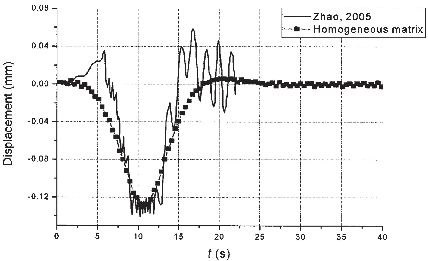
Fig.2 The displacement time history of 3rd node of the floating bridge subjected to load
Fu[18]carried out numerical simulation of dynamic response of floating bridge by employing finite element method,and also its corresponding model experiments.Fig.3 shows the displacement time history of the 6th node of the floating bridge subjected to 50 t load with velocity of 3.0m/s.The dot line in Fig.3 is the model test data which is transformed to a real bridge value in accordance with the experimental comparability principle.The solid line in Fig.3 is the calculation result of real bridge obtained by homogeneous matrix method.
As can be seen in Fig.3,when the load passes the floating bridge at speed of 3.0 m/s,the displacement wave has already spread to the location of the 6th node before the load,which makes its displacement time history present a slight fluctuation before the load arrives at the 6th node.A small amount of accumulation of displacement wave appears in front of the load when it moves on the floating bridge at a relatively low speed.The accumulation of the displacement wave is about 0.05 m when the velocity of load is 3.0 m/s.
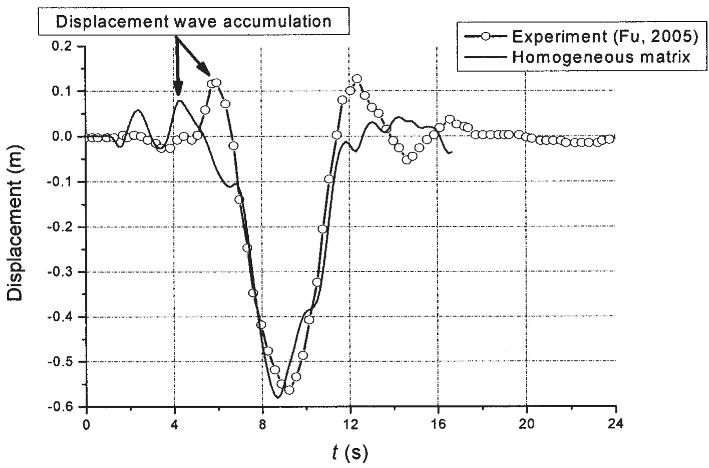
Fig.4 The displacement time history of the 6th node of the floating bridge subjected to 50 t load with the speed of 6.0 m/s
Fig.4 shows the displacement time history of the 6th node of the floating bridge subjected to the load with the speed of 6.0 m/s.The dot line shows the data gained from model tests,and the solid line presents the calculation result obtained by the homogeneous matrix method according to the engineering size of the floating bridge.The displacement wave accumulation reaches 0.1 m in Fig.4,which is twice as much as that subjected to moving load with the speed of 3 m/s.
The dynamic response of the floating bridge under a moving load with a higher speed was also carried out.Fig.5 shows the displacement time history of the 6th node of the floating bridge subjected to a load with the speed of 9.0 m/s.The dot line represents the data gained from model test and the solid line indicates the calculation result obtained by the homogeneous matrix method according to the engineering size of the floating bridge.As is shown in the experimental data in Fig.7,when the load velocity reaches 9.0 m/s,the amount of the displacement wave accumulation is close to 0.15 m,which is smaller than that obtained by the homogeneous matrix method but bigger than that under load with the velocity of 3.0 m/s or 6.0 m/s.
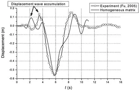
Fig.5 The displacement time history of the 6th node of the floating bridge subjected to 50 t load with the speed of 9.0 m/s
Owing to the limitation of controlled motor speed in the experiment,it is infeasible to carry out the test under the load with a faster speed.But in the calculation process the load speed can be further increased on the basis of the previous calculations which are verified by the experimental data.Fig.6 shows the displacement variation of the 6th node of the floating bridge subjected to load with the velocity of 10.0 m/s and 15.0 m/s.The horizontal axis is the dimensionless length and the longitudinal axis is the displacement of the node.The result shows that the amount of the displacement wave accumulation of the floating bridge has reached 0.12 m when the load passes with the speed of 10.0 m/s,and the amount of the displacement wave accumulation reaches as much as 0.24 m when the load passes with the speed of 15.0 m/s,which has seriously hindered the load from passing the bridge.This means that the effect of the displacement wave on moving load must be taken into account in practical engineering when loads pass the floating bridge with high speed.
In the continuous floating bridge model test,the experimental model is showed in Fig.7,the phenomenon of displacement wave accumulation is also found[19].The displacement wave will accumulate in front of moving load at the floating bridge when the speed of the load is high,and the amount is so large that it stacks like a “hill”in front of the moving load,as shown in the circle in Fig.8.It can be seen from the test site that the part of the floating bridge where the displacement wave accumulates has left the water surface.The reason why the floating bridge uplifts and leaves the water surface is that the floating bridge subjected to highspeed and heavy load stimulates the displacement wave to propagate forward.And the speed of load and the propagation speed of displacement wave are almost the same,which causes the accumulation of the displacement wave.
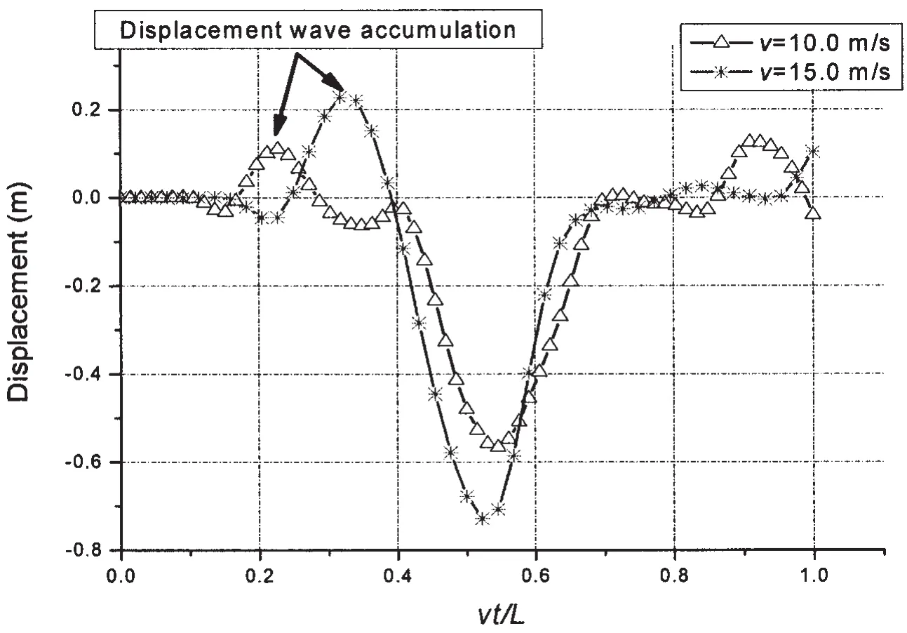
Fig.6 The displacement time history of the 6th node of the floating bridge subjected to 50 t load with high speed
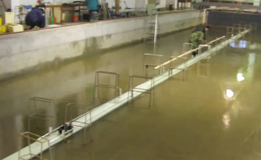
Fig.7 The experimental model of floating bridge subjected to high-speed and heavy load
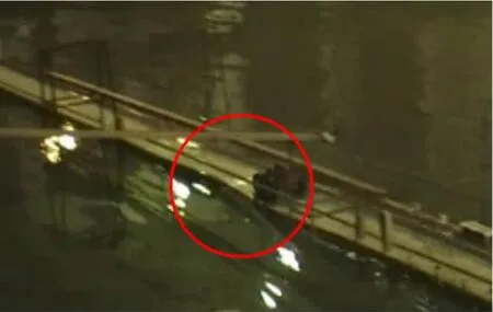
Fig.8 Snapshot of the distortion of the floating bridge subjected to high speed load
4 Conclusions
It is found by numerical simulation and corresponding model test that the displacement wave accumulation will arise when the floating bridge multi-body system is subjected to high speed and heavy load.The higher the speed is,the greater the displacement wave accumulation is.
The effect of the displacement wave accumulation is due to the small bending rigidity of floating bridge and the high speed of moving load.When the speed of the moving load catches up with that of the displacement wave propagating on the floating bridge,the displacement wave accumulation will occur.This kind of displacement wave accumulation may also occur in super-long flexible suspension bridge or cable-stayed bridge.Therefore,solving this new fluctuation problem has important academic significance and wide application prospects for engineering.
Acknowledgements
The authors gratefully acknowledge the financial support provided by the National Natural Science Foundation of China(Grant No.51009147).
[1]Timoshenko S.Vibration problem in engineering[M].3rd Edition.D.van Nostrand Company Inc.,1955.
[2]Sato Y,Okamoto S,Tamura C,et al.Analyses on accumulation of propagating ground surface wave under running train.Wave propagation,moving load and vibration reduction[C].Proceedings of the International Workshop Wave,2002:39-46.
[3]Bian Xuecheng.Ground vibration due to moving load at critical velocity[J].Journal of Zhejiang University(Engineering Science),2006,40(4):673-675.(in Chinese)
[4]Torbjorn Ekevid,Martin,Li X D,Nils-Erik Wiberg.Adaptive FEA of wave propagation induced by high-speed trains[J].Computers and Structure,2001,79:2693-2704.
[5]Torbjorn Ekevid,Nils-Erik Wiberg.Wave propagation related to high-speed train:A scaled boundary FE-approach for unbounded domains[J].Comput.Methods Appl.Mech.Engrg.,2002,191:3947-3964.
[6]Torbjorn Ekevid,Ha kan Lane,Nils-Erik Wiberg.Adaptive solid wave propagation--influences of boundary conditions in high-speed train applications[J].Comput.Methods Appl.Mech.Engrg.,2006,195:236-250.
[7]Yang Y B,Hung H H,Chang D W.Train-induced wave propagation in layered soils using finite/infinite element simulation[J].Soil Dynamics and Earthquake Engineering,2003,23:263-278.
[8]Chen Y J,Ju S H,Ni S H,Shen Y J.Prediction methodology for ground vibration induced by passing trains on bridge structures[J].J Sound Vib.,2007,302(4-5):806-820.
[9]Kouroussis G,Verlinden O,Conti C.Ground propagation of vibrations from railway vehicles using a finite/infinite-element model of the soil[J].Journal of Rail and Rapid Transit,2009,223(4):405-413.
[10]Chen Yit-Jin,Lin Shiu-Shin,Shen Yi-Jiun.Analysis model of ground vibration propagation for high-speed trains[J].Geo-Frontiers,2011,ASCE:3748-3755.
[11]Yang Y B,Hung H H,Kao J C.2.5D Finite/Infinite element approach for simulating train-induced ground vibrations[C].AIP Conf.Proc.,2009,1233:5-14.
[12]Hughes T J R,Reali A,Sangalli G.Duality and unified analysis of discrete approximations in structural dynamics and wave propagation:Comparison of p-method finite elements with k-method NURBS[J].Comput.Methods Appl.Mech.Engrg.,2008,197:4104-4124.
[13]Erkan Çelebi,Seyhan Firat,Günay Beyhan,et al.Field experiments on wave propagation and vibration isolation by using wave barriers[J].Soil Dynamics and Earthquake Engineering,2009,29(5):824-833.
[14]Legnani G,Casolo F,Righettini P,Zappa B.A homogeneous matrix approach to 3D kinematics and dynamics.Part 1:theory[J].Mechanisms and Machine Theory,1996,31(5):573-587.
[15]Legnani G,Casolo F,Zappa B,Righettini P.A homogeneous matrix approach to 3D kinematics and dynamics.Part 2:applications[J].Mechanisms and Machine Theory,1996,31(5):589-605.
[16]Wu Xiuheng,Zhang Lewen,Wang Renkang.Ship maneuverability and seakeeping[M].Beijing:China Communications Press,1988.
[17]Zhao Yubo.Numerical simulations of constrained multi-body systems[M].Hong Kong:The Chinese University of Hong Kong,2005.
[18]Fu Shixiao.Nonlinear hydroelastic analyses of flexible moored structures and floating bridge[M].Shanghai:Shanghai Jiao Tong University,2005.(in Chinese)
[19]Jiang Zhaobing.The displacement wave accumulation effect of the long floating bridge multibody system subjected to fast and heavy loads[M].Nanjing:the PLA University of Science and Technology,2008.(in Chinese)
- 船舶力学的其它文章
- Activities of Propulsion Design and Cavitation Test for Merchant Ships in CSSRC
- 3D Trajectory Tracking Control Platform Design for Deep Sea Open-framed Remotely Operated Vehicle based on Hydrodynamics Test
- Quasi-static Compressive Behavior of U-type Corrugated Cores Sandwich Panels
- Structural Dynamic Response Study of Large LNG Carriers under Sloshing Impacts in Tanks
- Research of Repair Major Joint Cracks of Offshore Platforms by Finite Element
- Theoretical Studies in Isolated Prop Model of Subsea Pipeline

