3D Trajectory Tracking Control Platform Design for Deep Sea Open-framed Remotely Operated Vehicle based on Hydrodynamics Test
FAN Shi-bo,LIAN Lian,REN Ping
(1 State Key Laboratory of Ocean Engineering,Shanghai Jiao Tong University,Shanghai 200240,China;2 Chinese Underwater Technology Institute,Shanghai Jiao Tong University,Shanghai 200231,China)
1 Introduction
With the significant technological improvement the field of computer science,cybernation,networks,communication and artificial intelligence and underwater vehicles are playing critical roles in performing both civilian and military missions,such as oceanographic survey,cable tracking and inspection,oil and gas exploitation and mine sweeping[1-3].These applications need a high precision trajectory tracking along the specified route.And due to the high cost of R&D and the adverse of oceanic environment,it is very necessary to design a 3-dimensional motion control platform to monitor the movement of UUV when operating under water[4-5].
In this paper,the numerical simulation platform of ROV is developed to shorten the R&D period and decrease the cost and risk.The designing concepts are guided by the idea of digital earth.Due to the inherent nonlineaity,high coupling and external disturbances,establishing a precise hydrodynamics model is the basis for maneuverability research and controlling platform.Accordingly,we manufacture the scaled model by 1:1.6,and conduct the towing test through VPMM and LAHPMM.Through the towing tests,we obtained the hydrodynamic coefficients and established mathematical model by 5 degree of freedoms for the ROV.
The 3D underwater objects are modeled by utilizing surface triangle subdivision method.The texture mapping and rendering technology are adopted to realize vivid scene of seabed.The numerical simulation platform is fulfilled by using 3D graphics library OpenGL on the Windows operating systems.
2 Hydrodynamic tests for ROV model
2.1 Test procedures
We manufactured the ROV model,and carried out towing test to obtain relating hydrodynamic coefficients.In the model test,we did not consider the influence of roll motion due to the special structure and layout characteristics[6].As shown in Fig.1,the ROV model was constructed by 1:1.6 according to the layout testing requirements.The model’s buoyancy material is made of wood,and the bottom chassis is made of steel.We only manufactured ROV itself without considering umbilical cable and sampling chassis.
And the main parameters of ROV model are summarized in Tab.1,including body size of the model,mass in air,displacement of volume.
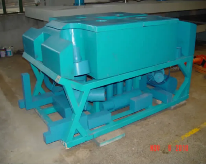
Fig.1 Open-framed ROV model

Tab.1 Parameters of ROV model
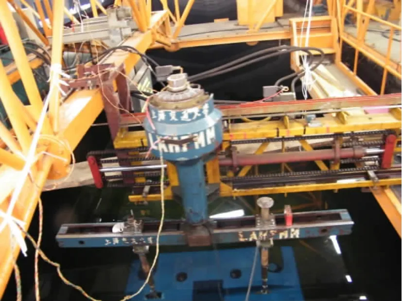
Fig.2 Purely heaving test on site
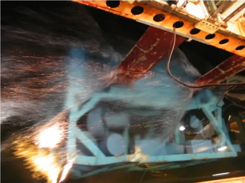
Fig.3 Purely pitching motion test
The main dimensionless coefficients of the vehicle were obtained in rectangle tank by using VPMM(Vertical Planar Motion Mechanism)and LAHPMM(Large Amplitude Horizontal Planar Motion Mechanism).Fig.2 shows the purely surging towing test of the ROV model,and the oscillation amplitude a=0.1 m;Fig.3 shows the purely pitching towing test of the ROV model at u=0.5 m/s,and the oscillation amplitude a=0.041 m.
2.2 Hydrodynamics coefficients
In order to decrease the error influence,data measured through tests need to be corrected by some algorithms.Maximum likelihood principle,error prediction method,recursion leastsquare technology and extend kalman filter have been adopted in a great number of papers to process test data[7-8].
We utilize least-square technique to estimate the hydrodynamics coefficients of the ROV.For the calculation of the nonlinear hydrodynamics coefficients,linear coefficients are firstly figured out through data regression of small degree,then the nonlinear coefficients are computed by combining large degree data and linear results.The dimensionless hydrodynamic coefficients are summarized in Tab.2.
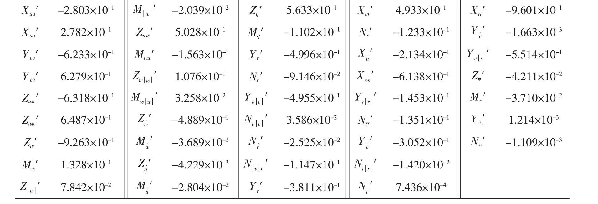
Tab.2 Hydrodynamics coefficients of ROV
3 Mathematical model
This section describes the kinematic and dynamic model of the ROV.Because the spatial motion of underwater vehicle has features of nonlinearity and high coupling,establishing an accurate mathematical model is the basis for the design of control system and maneuverability research[9-10].As depicted in Fig.4,the earth-fixed coordinate system and the body-fixed coordinate system are defined to facilitate the analysis of motion mathematical model.The fundamental concepts and definitions such as transformation matrix,reference frames,generalized velocity,generalized position,hydrodynamic coefficients,etc can be found in Ref.[11].
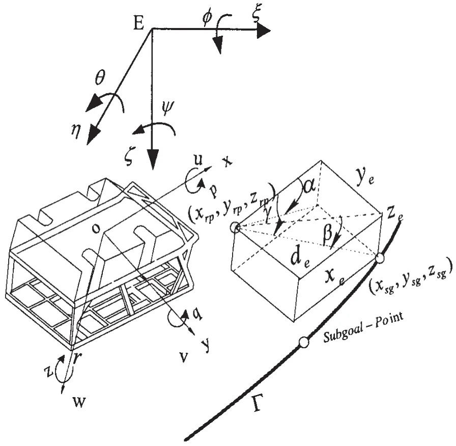
Fig.4 Frames of reference,state variables
The following factors are considered adequately to deduce and simplify the ROV mathematical model:
(1)The vehicle manufactured has the features of open-framed body structure and rectangle shape;
(2)The resistance along the y axis could not be measured by current test devices because the values of Ixand the sway damping are too large,and the relating coefficients with p can not be figured out;
(3)The vehicle will mainly operate on the horizontal planar,while the motion and maneuverability on the vertical planar only has small attack angles.
Accordingly,the 5-DOF motion mathematical model is set up by combining kinematics and dynamics equations,which are derived based on momentum theorem.The hydrodynamics equations are expressed as the following forms:
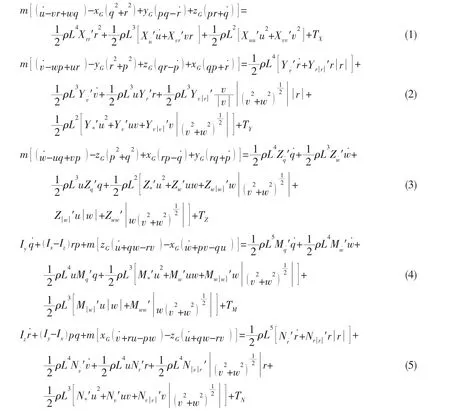

where m is the vehicle mass;L is the vehicle length;ρ is the density of seawater;(xG,yG,zG)is the center of gravity of vehicle;Xuu′…′are the linear or quadratic hydrodynamic coefficients;Tx,Tyand Tzare the thrust force along the body X,Y,Z,respectively;TMand TNare the thrust moments along the body Y,Z,respectively.And for the 5 DOF hydrodynamics equations,p=φ=φ˙=0.
4 Simulation platform design
The general developing procedure of the virtual visual simulating platform for ROV can be illustrated as Fig.5,which includes chart data processing,seafloor condition generating,vehicle modeling and trajectory tracking displaying.
4.1 Chart data processing
Chart data is the basis of generating seabed scene.And users can obtain some valuable information by utilizing the data,such as islands allocation,water depth,etc.The essential information in the virtual conditions is similar as the real oceanic chart data,including basic data and update data.The basic data is relevant with the natural environment,such as CTD,cays and rocks,depth.While the update data is related with human activities,such as seafloor cable,wrecks,beacons.Fig.6 depicts the designated sea area.
The main process of chart data includes the following steps:
(1)Chart files importing and removing,including file structure,index information,chart number and names.
(2)Chart data extracting,including the longitude and latitude of the designate layer and water depth.
(3)Chart area selecting,capture the corresponding region according to different simulating design.
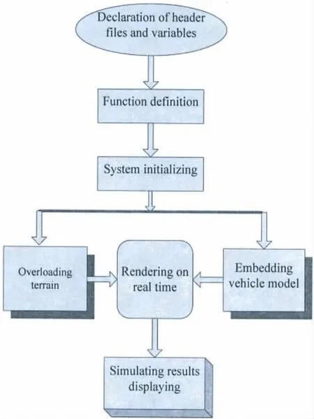
Fig.5 Procedure chart of the virtual vision simulating platform
(4)Chart measuring,transform the chart planar coordinates to geographic coordinates through chart proportional scale.
(5)Chart data parameters setting,storage the corresponding data information(longitude and latitude value,depth value)into the data base for the calling by seabed scene generating.
4.2 3D seafloor scene generating
Using 3D geography information system theory,3D underwater objectives are established based on OODM(Object Oriented Development Method)and triangle surface partition method.Special topology relations of two discretionary entities are analyzed based on the topology relations.According to the layer features,the underwater objects structure can be defined as follows:

Fig.6 Profile of islands allocation on designated sea area
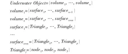
We also consider the property of the entities due to the texture and shines characteristic.Each polygon surface is deemed as an object,which includes some critical data structures,such as texture name,material,etc.The 3D seafloor scene models with texture and grids are shown in Fig.7 and Fig.8.
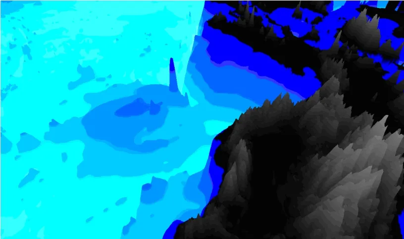
Fig.7 3D seafloor rendering environment

Fig.8 3D seafloor relief environment with grids
4.3 Vehicle modelling
OpenGL is the most widely adopted 2D and 3D graphics API in the industry,which has been applied in a great variety of computer simulation platforms.It is window-system and op-erating-system independent as well as network-transparent.OpenGL enables developers of software for workstation,and supercomputing hardware to create high-performance,visually compelling graphics software applications,in markets such as game development,manufacturing,medical,robotics and virtual reality[12].The following functions must be paid high attention in the model drawing program:glPushMatrix(),glPopMatrix(),glBegin(),glEnd(),and they should be called in pairs respectively.Furthermore,the function of glTranslatef()also should be employed correctly to guarantee the model be drawn in the designated window area.
We devise the open-framed underwater vehicle by using the drawing function of OpenGL,such as rotation,translation and transformation.Considering the complexity and verisimilitude of the vehicle,triangle method and texture mapping techniques are introduced to create the ROV model with high precision.Fig.9 gives the grid shape of the model,and Fig.10 renders the texture for the 3D vehicle model.

Fig.9 3D grid model of ROV
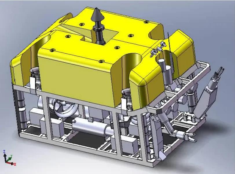
Fig.10 3D rendered model of ROV
5 Simulation results
The advantages of the simulation platform for the trajectory tracking control lie in the interactive and stereoscopic features.The users can monitor the vehicle motion effects through different points of view,such as bottom view,top view.And the motion modes of the vehicle include static hovering,cruising,rotating at constant depth.

Fig.11 ROV moving along slope trajectory
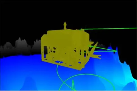
Fig.12 ROV moving along helix trajectory
The numerical simulation platform is developed by employing VC++6.0 integrated soft-ware.And OpenGL provides various observing modes and triggering events by single button,which can be fulfilled by the following functions:glTranslatef(),glRotatef()and glScalef().
The trajectory tracking simulation results are shown in Figs.11-12.It can be seen in Fig.11 that the vehicle cruises along the slope trajectory by keeping the specified attitude.Fig.12 depicts the vehicle moves along the helix trajectory.
6 Conclusions
In this paper,3D trajectory tracking control platform is developed for remotely operated vehicle,which includes chart data processing,seafloor condition generating,vehicle modeling and trajectory tracking displaying.We manufactured the scaled model by 1:1.6,and conducted the towing test through VPMM and LAHPMM for the ROV.According to the towing tests results,we figured out the relating hydrodynamic coefficients and found hydrodynamics equations by 5 DOF for the ROV.The platform can be applied into many practical fields,such as simulation research of seafloor environment,motion and maneuvering simulation of underwater vehicle,debugging of control system and manipulating training.The simulating results show the validity of modeling and algorithm.It provides an effective approach for the R&D of underwater vehicle.
In the future,we will embed the numerical platform into real operating missions,such as pipeline inspection,vehicle launching and docking.
[1]Repoulias F,Papadopoulos E.Three dimensional trajectory control of underactuated AUVs[C]//Proceedings of the European Control Conference,2007.Kos,Greece,2007:3492-3499.
[2]Fang C,Anstee S.Coverage path planning for harbor seabed surveys using an autonomous underwater vehicle[C]//IEEE OCEANS’10 Sydney.Australia,2010.
[3]Nicholson J W,Healey A J.The present state of autonomous underwater vehicle(AUV)applications and technologies[J].Marine Tech.Soc.J,2008,42:44-51.
[4]Zhao J M,Xu Y R,Lei L.A simulator for the test of intelligent path planning of AUV[J].Journal of System Simulation,2004,16(11):2448-2450.(in Chinese)
[5]Wang Y H,Wang S X.Dynamic modeling and three-dimensional motion analysis of underwater gliders[J].China Ocean Engineering,2009,23(3):489-504.
[6]Avila J P J,Adamowski J C.Experimental evaluation of the hydrodynamic coefficients of a ROV through Morison’s equation[J].Ocean Engineering,doi:10.1016/j.oceaneng,2011.09.032.
[7]Yoon B H,Li J H,Cho J S.A study on the CFD-based nonlinear modeling for intelligent autonomous underwater vehicle‘PSURO’[C]//In Proc.of the Autumn Workshop of Underwater Robotics Research Society in Korea.Busan,Korea,2009:81-86.
[8]Burger M,Pettersen KY.Trajectory tracking for marine vehicles under constant disturbances:Controller design and tuning[C]//OCEANS’10 IEEE.Sydney,Australia,2010.
[9]Caffaz A,Caiti A,Casalino G,Gualdesi L.A low-cost autonomous underwater vehicle combining glider and AUV capabilities[J].Ocean Engineering,2009,36(1):24-38.
[10]Kumar R P,Dasgupta A,Kumar C S.Robust trajectory control of underwater vehicles using time delay control law[J].O-cean Engineering,2007,34(4):842-849.
[11]Fossen T I.Marine control systems:Guidance,navigation and control of ships,rigs and underwater vehicles[M].Marine Cybernetics,2002.
[12]Dave S,Jackie N,Tom D.OpenGL programming guidance(4th edition)[M].Beijing:People’s Post and Telecommunication Publishing House,2009.
- 船舶力学的其它文章
- Activities of Propulsion Design and Cavitation Test for Merchant Ships in CSSRC
- Quasi-static Compressive Behavior of U-type Corrugated Cores Sandwich Panels
- Structural Dynamic Response Study of Large LNG Carriers under Sloshing Impacts in Tanks
- Research of Repair Major Joint Cracks of Offshore Platforms by Finite Element
- An Application of Homogeneous Matrix Method of Multi-body System to the Dynamic Response of Floating Bridge
- Theoretical Studies in Isolated Prop Model of Subsea Pipeline

