Activities of Propulsion Design and Cavitation Test for Merchant Ships in CSSRC
LU Fang,DING En-bao,XIN Gong-zheng,HUANG Hong-bo,MA Yan
(China Ship Scientific Research Center,Wuxi 214082,China)
1 Introduction
2012 is the 10th year for the large cavitation channel of CSSRC got into running since 2002.During last ten years,the ship building in China is rapidly increasing by more than 40%every year,it directly results in more and more requirements for the design and test research of propulsion.Due to the fuel price is higher and higher,the demand of high efficiency propulsion systems and energy saving devices are raised continuously.This paper describes the works performed in CSSRC for the design and test of propulsion mainly during last 10 years.
2 Propeller design and cavitation test
2.1 Propeller design
CSSRC has been engaged in researching on hydrodynamics of propulsors and developing methodology of propulsor design and performance prediction for more than 50 years.A propeller design software called PARADS was developed,it can be used for propeller design and propeller performance prediction.Nowadays,all designed propulsions can be verified by using advanced surface panel method or CFD method of viscous flow to check their performance.Hundreds of design includes the conventional propeller,high skewed propeller,ducted propeller and contra-rotating propellers for different kinds of vessels such as oil tankers,bulk carriers,container vessels,LNG vessels,semi-submerged vessels and multi-purpose vessels.Now more than 2000 merchant ships’propulsion designed by CSSRC are sailing all over the world.Tab.1 lists some examples of the CSSRC propeller design.

Tab.1 Examples of propeller designed by CSSRC
2.2 Propeller cavitation test[1]
The test for the propeller cavitation and pressure fluctuation is performed in the large caivitation channel[1].This channel has a closed test section with the width of 2.2 m,height of 2.2 m and length of 11.8 m.So a total ship model with the all appendages can be installed in the test section to carry out the test.The velocity can be up to 15 m/s and the pressure can be changed between 30 kPa and 0.3 MPa.Fig.1 is the photo of the test section.Fig.2 and Fig.3 are some examples of the model installation for propeller cavitation test.The pick-ups are installed inside the ship stern and above the propeller model to measure the pressure fluctuation induced by propeller cavitation.Normally three CCD cameras in front of and behind of the propeller are used for cavitation observation.
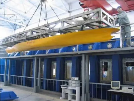
Fig.1 The test section of the channel
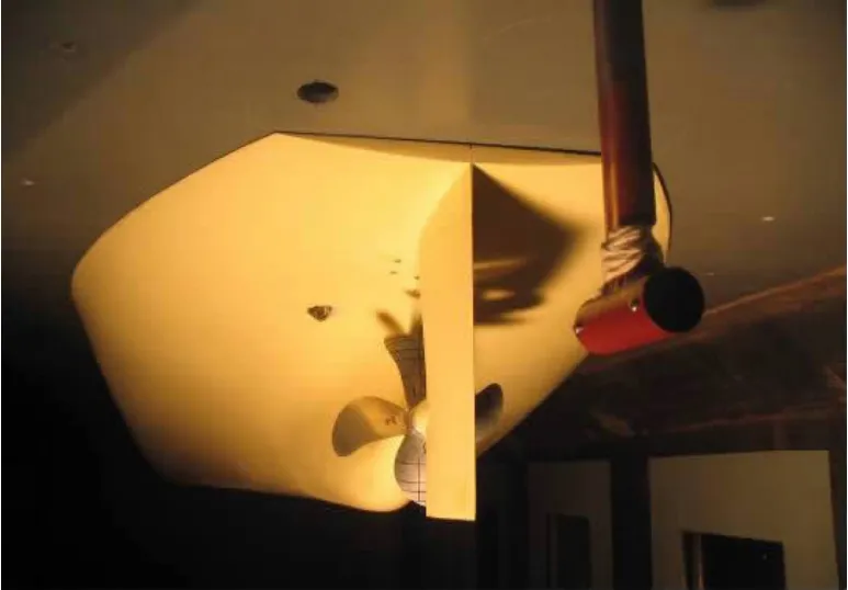
Fig.2 Installation for a single propeller test
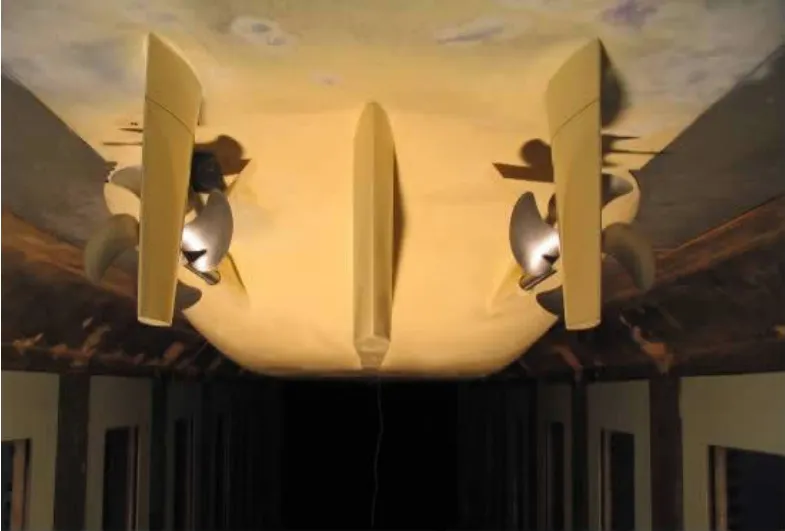
Fig.3 Installation for a twin screw propeller test
2.3 The erosion solving methodology[2]
During last years,some cavitation erosion problems were solved through test research and analysis and the erosion predicted method was developed.Fig.4 shows an example of propeller erosion caused by the propeller pressure side cavitation as tested in Fig.5.The test clearly shows the reason of the erosion.According to this test results,we improve the leading edge geometry as show in Fig.6.The model test after improving reveals that it is quite effective as shown in Fig.7,the propeller blade was free of cavitation on pressure side after 2-years ship running,it is proved that this method for solving erosion problem is quite successful.
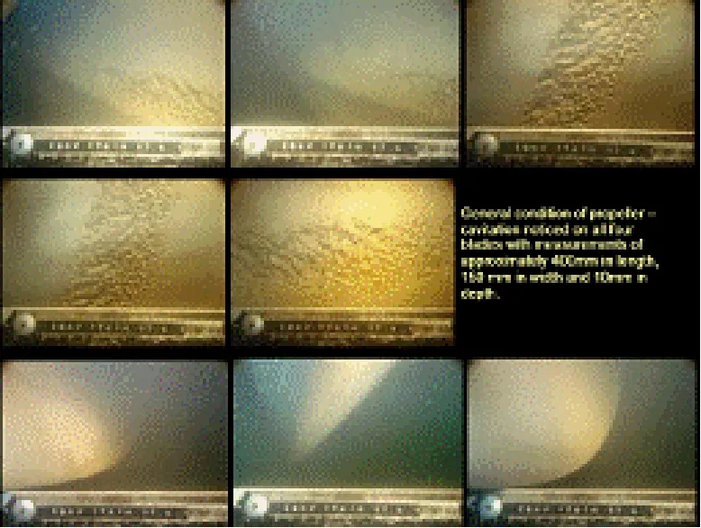
Fig.4 Cavitation erosion on a CV propeller
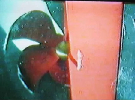
Fig.5 Cavitation caused erosion on pressure side
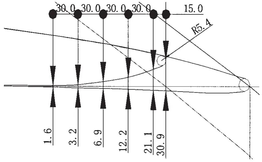
Fig.6 The improving of the leading edge
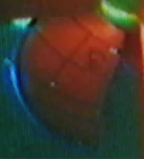
Fig.7 The test result after leading edge improvement
In order to predict the propeller erosion risk caused by the cavitation,the paint methods were developed and successfully validated.Fig.8 presents an example erosion risk caused by the tip vortex cavitation.Two kinds of paint methods were set up on the different blades and the test results showed good agreement.Also the correlation between the cavitation and the erosion risk can been seen compared in Fig.8 and Fig.9.
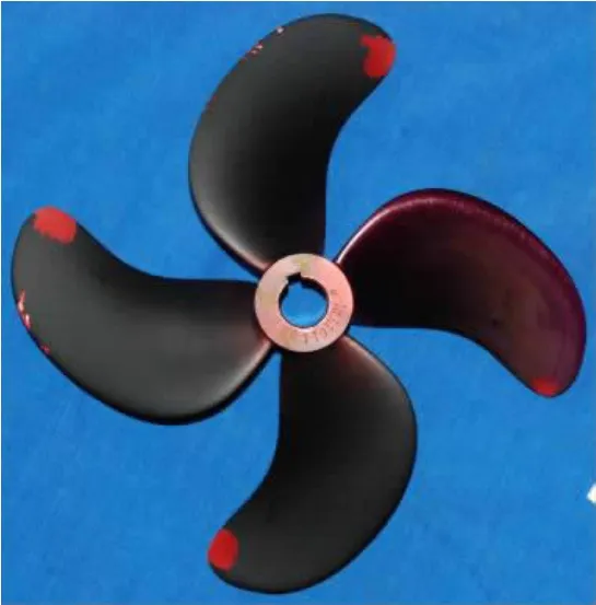
Fig.8 The paint test results of the cavitation erosion

Fig.9 The strong tip vortex cavitation
2.4 The vibration solving methodology[3]
The vibration caused by the propeller cavitation is often serious problems for the ships.The first choice for solving such problems is to improve the propeller design,but sometimes it is impossible to settled just by redesigning the propeller.Fig.10 shows a serious vibration caused by Propeller-Hull-Vortex(PHV)cavitation as shown in Fig.11.
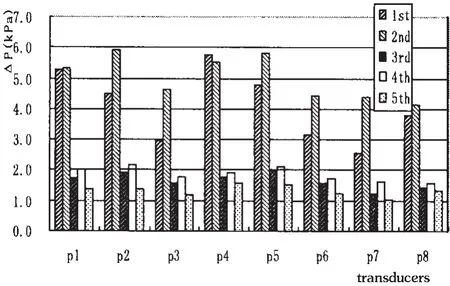
Fig.10 Pressure fluctuation caused by PHV cavitation
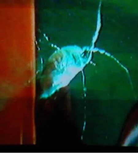
Fig.11 PHV cavitation
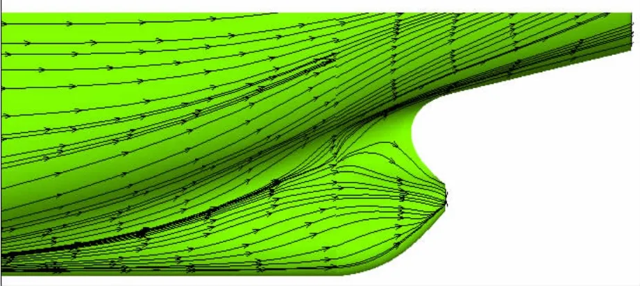
Fig.12 The separation of the boundary layer
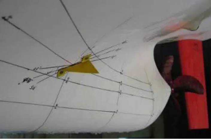
Fig.13 The installation of the VGs

Fig.14 The cavitation after installed VGs
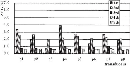
Fig.15 The pressure fluctuation after installed VGs
In order to solve this issue,some different propeller designs are tried to apply for but failed.This is mainly caused by the separation boundary layer as shown in Fig.12.So the vortex generations(VG)were installed on both side of the ship stern showed in Fig.13.It was very successfully validated by the VGs,it was free of the PHV as shown in Fig.14 and the pressure fluctuation decreased by more than 30%for 1st blade order and nearly 50%for 2nd blade order values as shown in Fig.15.
With this method,another vibration problem was well settled for a bulk carrier.Fig.16 shows the application of the VGs on the ship.The trial results showed that the vibration level at the ship stern was reduced by 30%.
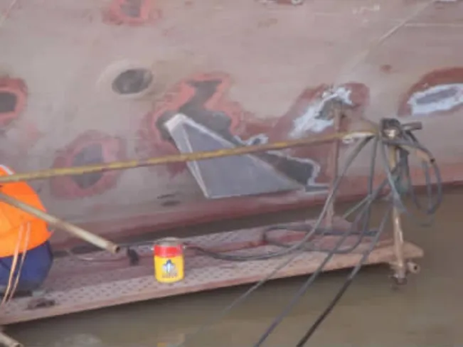
Fig.16 Application of VGs on a BC
3 Surface-piercing propellers(SPPs)design and their applications[4-5]
For high speed more than 30 knots crafts,SPP is a promising option for propulsion system as they have higher efficiency and are free of the cavitation erosion compared to the conventional propeller.During last years,CSSRC has developed a series of SPPs covered the speed from 30 to 70 knots,with the power of 235~525 kW.Named model BTZ-1200,BTZ-2400 and BTZ-3600 for the torque of 1800 N·m,2400 N·m and 3600 N·m,respectively.The hydro-performance for SPP was tested in the depressurized towing tank as shown in Fig.17.An example of the SPP with the driving system is shown in Fig.18 and an application of SPP in Fig.19.
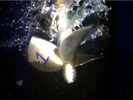
Fig.17 The performance test in the depressurized towing tank for a SPP
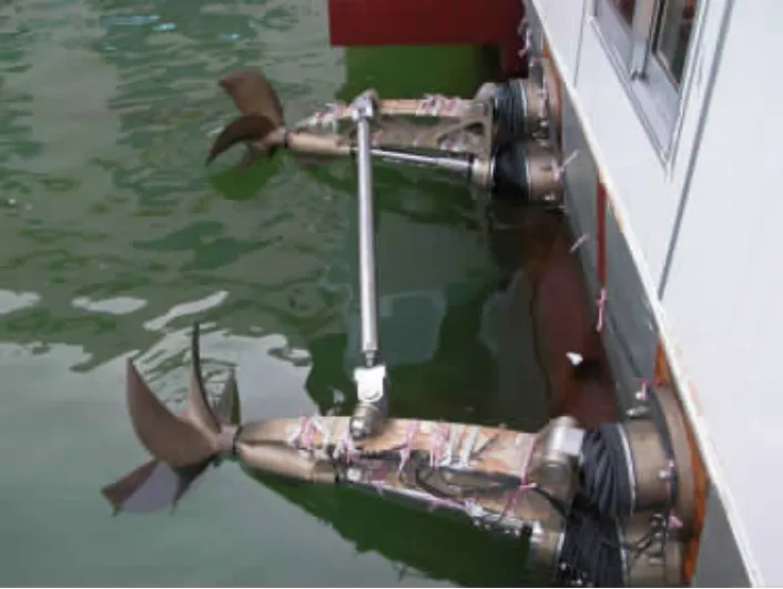
Fig.18 SPP with the driving system
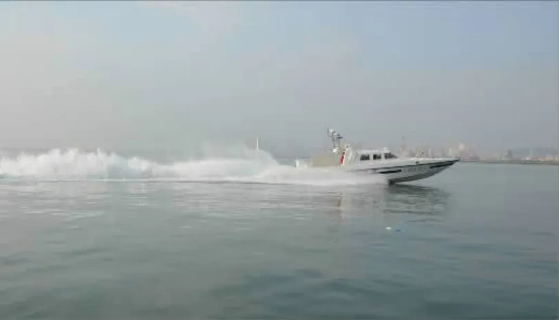
Fig.19 A craft propelled by SPP system
4 Energy saving devices and their applications
Due to the higher and higher fuel cost and the restriction of the carbon emission all over the world,the energy saving device research and design are required to account for this situation.One of the most effective and simplest way is the hub vortex absorb fin(HVAF).CSSRC has developed an aggregative design method for the propeller and HVAF.And the test method for the combination of propeller and HVAF in cavitation tunnel(as Fig.20)is developed to improve the design and the prediction.The force performance was compared with and without HVAF in the cavitation tunnel.By the aggregative design method,the total propeller efficiency is increased by more than 2%normally in the test results(Fig.21).For the full scale prediction,the efficiency can be increased by 4%~5%.The additional cost for the HVAF can be taken back by saving the fuel cost during one year.During these years,the aggregative propeller and HVAF have been designed for several cargo vessels such as 39 k DWT,75 k DWT and 177 k DWT.This aggregative design is also applied to the container vessel.
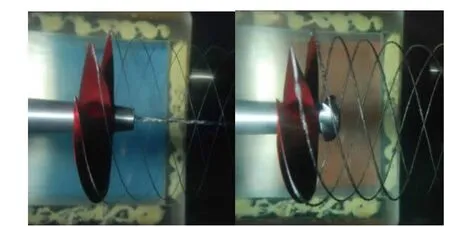
Fig.20 The test for combination of propeller and HVAF
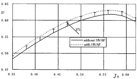
Fig.21 The efficiency comparison with and without HVAF
5 Conclusions
During last ten years,the propeller design and test method for merchant ships in CSSRC have been successfully developed and performed.Some methodology for solving the problems caused by propeller cavitation were also established and made a triumphant application.The SPPs for high speed craft were researched and a series of SPPs was designed for a range of usage.The design method and the performance test of saving energy devices mainly the HVAF with the propeller were developed and successfully applied for the different kind of vessels.
[1]Wang T K,Lu Fang,et al.A new large cavitation channel in China Ship Scientific Research Center[J].J of Hydrodynamics,2003,15(4):59-62.
[2]Lu Fang,Ding Enbao,et al.The investigation of face cavitation erosion on propeller blades[C]//Pro.of 3rd PAAMES and AMEC2008.Chiba,Japan,2008.
[3]Lu Fang,Zhang Zhirong,et al.An application of the vortex generator to control the PHV cavitation[J].J Ship Mechanics,2009,13(6):873-879.
[4]Huang Hongbo,Ding Enbao,et al.Experimental investigation of unsteady forces for a surface piercing propeller[C]//SuperFAST’2008.Saint-etersburg,RUSSIA,July 2008.
[5]Ding Enbao.A series of surface piercing propellers and its application[C]//FAST’2007.Shanghai,China,Sep.2007.
- 船舶力学的其它文章
- 3D Trajectory Tracking Control Platform Design for Deep Sea Open-framed Remotely Operated Vehicle based on Hydrodynamics Test
- Quasi-static Compressive Behavior of U-type Corrugated Cores Sandwich Panels
- Structural Dynamic Response Study of Large LNG Carriers under Sloshing Impacts in Tanks
- Research of Repair Major Joint Cracks of Offshore Platforms by Finite Element
- An Application of Homogeneous Matrix Method of Multi-body System to the Dynamic Response of Floating Bridge
- Theoretical Studies in Isolated Prop Model of Subsea Pipeline

