Structural Dynamic Response Study of Large LNG Carriers under Sloshing Impacts in Tanks
LU Ye,TENG Bei,QI En-rong,CHEN Xiao-ping
(1 China Ship Scientific Research Center,Wuxi 214082,China;2 Wuxi Institute of Communications Technology,Wuxi 214151,China)
1 Introduction
It is important that natural gas becomes primary energy with intensifying environmental awareness and the continuous decrease of oil.Liquefied natural gas(LNG)market has entered a rapid growth by development of the floating production storage and offloading,and LNG transport.Membrane LNG carriers become large-scale due to its excellent shipping economy.In addition,large LNG carriers need partial filling operation due to the new trade and offshore loading and offloading.To develop large-scale membrane LNG carrier,containment systems structures need enough fatigue and ultimate strength under quasi-static and sloshing impact loads in tank,and sloshing research is particularly important when the traditional condition including ship scales and operational status has been greatly changed.
Sloshing is the motion that liquid movement has free surface in the tank with partial loading under the external excitation.When the external excitation frequency is close to the natural frequency of the liquid(in particular the natural frequency of the lowest order),the liquid has quite impact on liquid bulkhead,and also leads to serious failure and damage to structures[1-2].Tank sloshing research methods can be summarized as the following three categories[3-6]:(1)Theoretical analysis,(2)Model test,and(3)Numerical simulation.
Det Norske Veritas(DNV)is the first classification society that published liquefied carriers guideline,which can carry out model test on LNG carriers under sloshing with advanced test equipment,according to the scale of 1/20 and the tank capacity up to 250 km3[7].DNV JIP program has started study on the membrane type LNG tank sloshing with real scale measurement in 2007.American Bureau of Shipping(ABS)published Strength Assessment of Membrane-type LNG Containment Systems under Sloshing Loads in 2006,which specified the sloshing model test procedures and assessment methods of sloshing loads[8].Paik[9]studied the ultimate limit state design and dynamic response of construction under sloshing loads.Currently,the tank sloshing studies in the following areas have made some progress[10-11]:(1)Sloshing test device,(2)Characteristics of the impact of sloshing,(3)Model test results analysis,(4)Computational fluid dynamics(CFD)applications,and(5)Sloshing assessment.
Researches on the tank sloshing problem mainly focus on the theoretical analysis and numerical simulation in China.The containment system structures of large LNG carriers were studied on elasticity effects on the impact of sloshing load by Qi,et al,who considered them as simply supported copper panel in a plexiglass model,measured their dynamic strain under the sloshing impact[12-14].
In this paper,ultimate capacity of the No.96 type containment systems of large LNG carriers is studied using nonlinear finite element method and failure modes with different border conditions are analyzed in details.Then,dynamic responses of containment systems under sloshing impact loads with different pressure peak and duration times are studied using explicit method and dynamic failure characteristics at different situation are studied.Finally,critical pressure load formulae are derived based on the proportional limit and the abruptly increasing permanent deflection,suggestions for design criteria and safety assessment are also given.
2 Ultimate capacity of tank containment systems
No.96 type LNG carriers tank containment systems consist of box structures.A total of 150000 m3LNG ships needs 51444 box structures,which are composed of two layers.The size of the box is 1140 mm long,999 mm wide,and 530 mm height,shown in Fig.1.The primary box has seven longitudinal girders with the height of 230mm;the second box has six transverse floors with the height of 300mm.The boxes are filled with silicon-treated perlite.
A series of tensile coupon tests was carried out with different thicknesses of plywood,which is isotropic brittle material.Taking into account the wood composed the plywood is elastic-plastic material,this paper will simplify the plywood as the isotropic elastic-plastic material.The elastic modulus obtained by the mean modulus of elasticity in tensile coupon tests,is E=7937 MPa,the yield strength of plywood takes the mean of 0.75,with σs=25.5 MPa.
The ultimate strength of the box structures under static pressure loads was calculated by nonlinear finite element method,with the boundary conditions of the top plate dealt with free,simply supported and rigid.Neither perlite nor Invar is included in the modeling.A total of 21008 plate-shell elements were employed for modeling the entire structure.For the box structure is supported by the inner hull of the ship,where the boundary condition is dealt with as a rigid floor.Figs.2-4 show the von Mises stress distribution,displacement distribution and the pressure versus lateral deflection under the boundary conditions of the top plate being with free.It seems that the lateral girders of the second layer were buckling,most of which have reached the yield strength of material,maximum displacement of 9.097 mm.Figs.5-7 show the von Mises stress distribution,displacement distribution and the pressure versus lateral deflection under the boundary conditions of the top plate being with simply supported.It seems that the lateral girders of the second layer were buckling,most of which have reached the yield strength of material,and the middle girders have been buckling,maximum displacement of 9.166 mm.Figs.8-10 show the von Mises stress distribution,displacement distribution and the pressure versus lateral deflection under the boundary conditions of the top plate being with rigid.It seems that the middle girders of the second layer were buckling,most of which have reached the yield strength of material,maximum displacement of 2.529 mm.Tab.1 shows that the ultimate strength of box structure under different boundary conditions,with the boundary conditions of the top plate from free to rigid,which the failure mode of box structure changed from the lateral girders buckling to the middle girders buckling,with a slight increase in ultimate strength.

Fig.1 Dimensions of the No.96 insulation box structure[9]
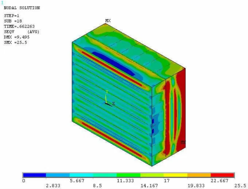
Fig.2 Von Mises stress distribution of the entire box structure under the boundary condition dealt with free
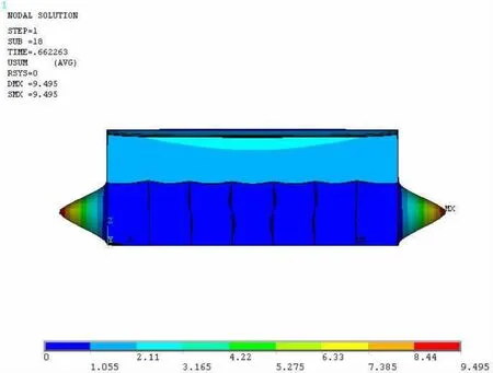
Fig.3 Deformed shape of the entire structure at the ultimate limit state under the boundary condition dealt with free
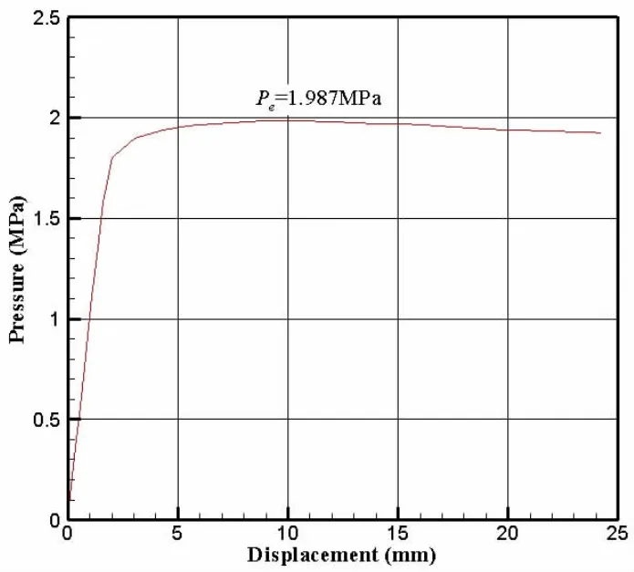
Fig.4 Pressure versus deflection of the entire box structure under the boundary condition dealt with free
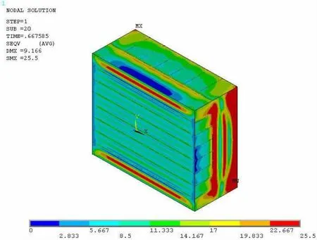
Fig.5 Von Mises stress distribution of the entire box structure under the boundary condition dealt with simply supported

Fig.6 Deformed shape of the entire structure at the ultimate limit state under the boundary condition dealt with simply supported
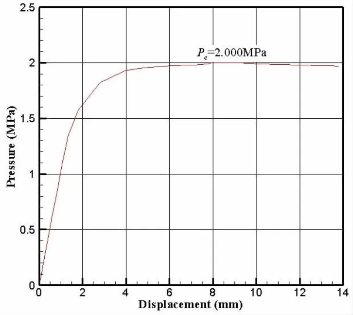
Fig.7 Pressure versus deflection of the entire box structure under the boundary condition dealt with simply supported

Fig.8 Von Mises stress distribution of the entire box structure under the boundary condition dealt with rigid
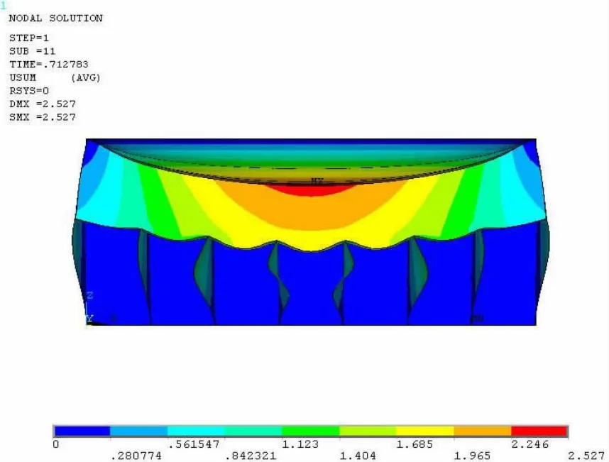
Fig.9 Deformed shape of the entire structure at the ultimate limit state under the boundary condition dealt with rigid

Fig.10 The pressure versus deflection of the entire box structure under the boundary condition dealt with rigid

Tab.1 Ultimate strength of tank containment systems under different boundary conditions
The failure modes of the ultimate strength analysis were similar with the top plate dealt with rigid in Fig.11,but Fig.12 from the ABS test shows that the boundary condition of the top plate should be dealt with simply support.In addition,the ultimate strength calculation of this paper is greater than the Ref.[9],due to different material properties,whereas it was not explicitly given that the elastic modulus or yield strength in calculation in Ref.[9].
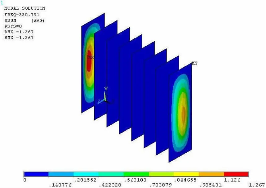
Fig.11 Linear buckling modal of box structure
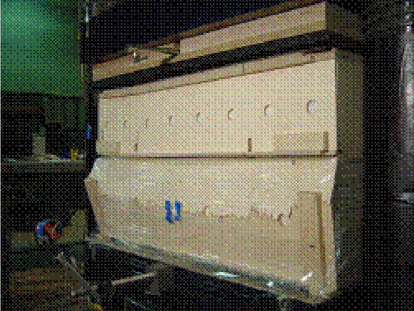
Fig.12 Buckling modal test of box structure[8]
3 Dynamic response of the copper panel under sloshing load in model experiments of sloshing in a tank of a large LNG carrier
This paper analyzed the results on the measure of dynamic strain of panel after the model experiments of sloshing in a tank of a large LNG carrier,used test data of sloshing loadtime curve by ANSYS software to simulate the dynamic response of panel under sloshing,and compared the calculation results with test data.
The model as shown in Fig.13 is given that the copper panel has 20 mm×20 mm in size,0.3 mm in thickness,8900 kg/m3in density,117 GPa in elastic module,0.32 in Poisson’s ratio,and 400 MPa in yield strength.A bidirectional strain gauge was disposed in the center of each copper panel to measure dynamic stresses refer to Fig.14.Fig.15 is sketch map of test model and measuring points.Fig.16 show that sloshing load-time curve in period of 5 s under±5°pitching at 10%L filling level from test data.While the frequency is 0.625 Hz on the condition of±5°pitching at 10%L filling level,the peak of load and strain has 1.6 s apart in test data.Fig.17 shows that wave time history of front bulkhead and back bulkhead under±5°pitching at 10%L filling level.Due to the water in tank from front bulkhead on pressure sensors to back bulkhead on strain gauges on the copper panel,the peak of wave height has a few seconds apart as the same as the peak space of load and strain data.It is shown that the copper panel has been applied a sloshing load taking from test data to ANSYS software,a period of section,under the boundary condition dealt with simply supported.Fig.18 compared the results on calculation with test data at the same period of time which were quite consistent,although the peak values of strain in calculation and test are slightly different due to water sloshing indefinitely from one side to another side.It has been concluded that a valid approach to the calculation of simulating the dynamic response of tank structures of large LNG carrier under sloshing loads as the same as panel,which has been properly proved by test data.
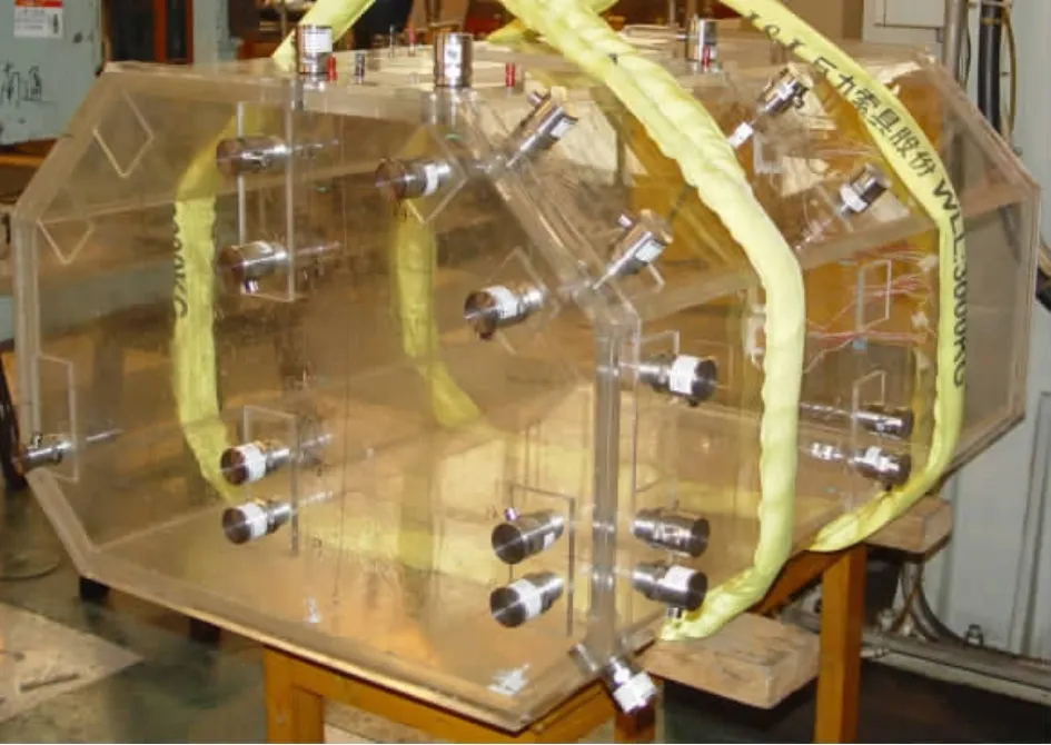
Fig.13 Test model after arrangement of measuring points
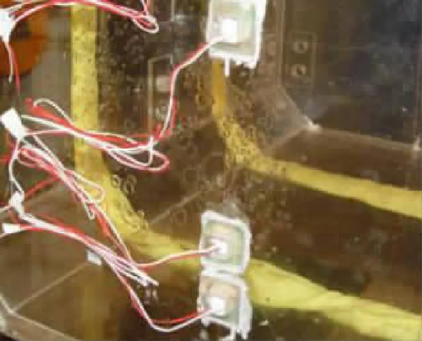
Fig.14 Strain gauge arrangement on the copper panel

Fig.15 Sketch map of test model and measuring points

Fig.16 Sloshing load-time curve under±5°pitching at 10%L filling level in test data
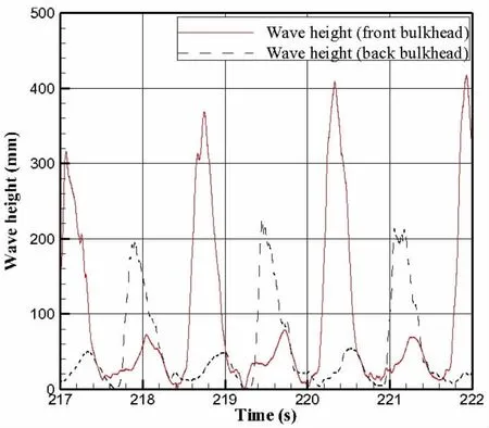
Fig.17 Wave time history of front bulkhead and back bulkhead under±5°pitching at 10%L filling level
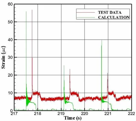
Fig.18 Strain-time curve comparison on calculation with test data under ±5°pitching at 10%L filling level
It is evident that when the duration time is shorter than the natural period of structure,the duration time is the main factor to the impact load,and when the duration time is longer than the natural period of structure,the peak pressure is the main factor to the impact load.For the sloshing loads,the duration time is shorter than the natural period of structure but not a little,therefore both peak pressure and duration time should be considered.
4 Dynamic response of the tank structures under sloshing load
The dynamic simulation of the tank containment systems under sloshing is calculated by explicit integral.Sloshing impacts are applied as triangle loading type,which is characterized by two parameters,namely,peak pressure Pmaxand duration time Tduration.As the quasi-static pressure loading case,neither perlite nor Invar is included in the modeling.A total of 21008 plate-shell elements were employed for modeling the entire structure.For the boundary conditions,the bottom of which is dealt with rigid floor and the top of which is dealt with simply support.
Figs.19-22 show the distribution of stress,deformation and time history,when peak pressure is 3 MPa and duration time is 2 ms.Fig.19 presents the von Mises distribution with peak pressure 3 MPa,while the lateral girders of secondary box structure were firstly buckling.Figs.20-21 show the von Mises stress distribution and the deformed shape of the structure after dynamic pressure loading is end,where the middle girders of the secondary box structure have little stress,and maximum deformation occurs in the lateral girders of the secondary box and the deformation of the top plywood was small.Fig.22 is a time history of deformation,with a large deformation.
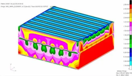
Fig.19 Von Mises stress distribution when the sloshing load with peak pressure of 3 MPa and duration time of 2 ms
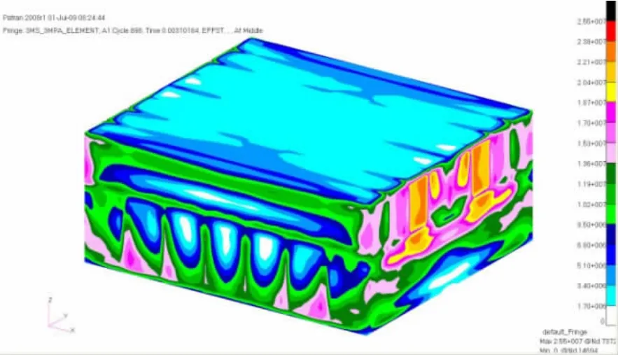
Fig.20 Von Mises stress distribution after the sloshing load with peak pressure of 3 MPa and duration time of 2 ms
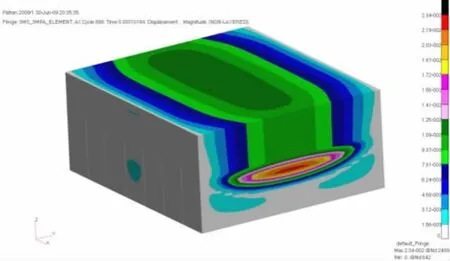
Fig.21 Deformation after the sloshing load with peak pressure of 3 MPa and duration time of 2 ms

Fig.22 Permanent deflection versus time history for peak pressure of 3 MPa and duration time of 2 ms
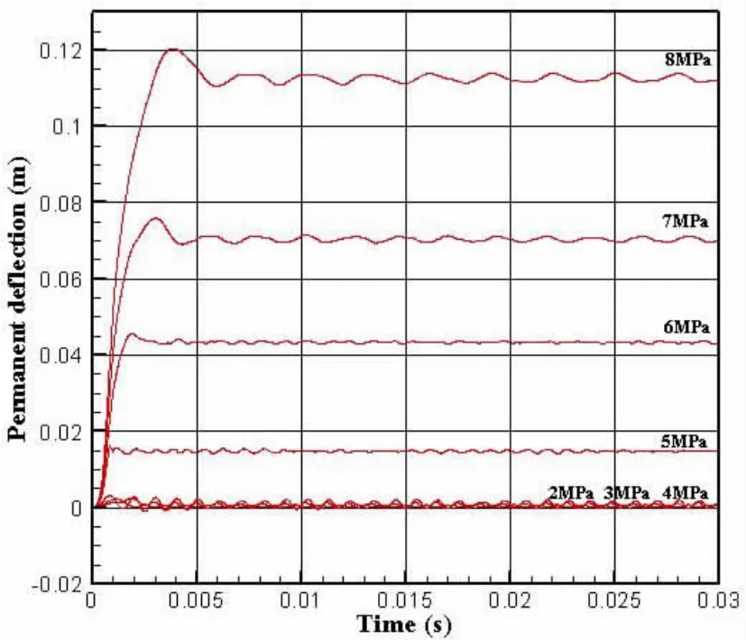
Fig.23 Permanent deflection versus time history with varying the peak pressure for duration time of 1 ms

Fig.24 Permanent deflection versus time history with varying the peak pressure for duration time of 2 ms

Fig.25 Permanent deflection versus time history with varying the peak pressure for duration time of 3 ms

Fig.26 Permanent deflection versus time history with varying the peak pressure for duration time of 5 ms
Fig.23 shows a summary of the permanent deflection versus time history with peak pressure at 2 MPa,3 MPa,4 MPa,5 MPa,6 MPa,7 MPa,and 8 MPa when the duration time is fixed at 1 ms.Figs.24-26 show a summary of the permanent deflection versus time history with peak pressure at from 2 MPa to 6 MPa when the duration time is fixed at 2 ms,3 ms and 5 ms.The results show that the value of permanent deflection increased with the peak pressure when the duration time is still,a clear vibration occurs in the equilibrium position of structure when the peak pressure is small,and the structures have the plastic deformation and also permanent deflection when the peak pressure is big.The structures of the deformation increase as significantly as the duration at a fixed load.Moreover,damage of the top plywood structures is the greatest with shorter duration time,and the lateral girders of secondary box structure have the largest deformation when duration time continues longer.
5 Tank containment systems design and safety assessment guidelines
For the dynamic response analysis of tank containment systems under the sloshing loads,the permanent deflection versus peak pressure with different duration time is obtained in Figs.27-30.

Fig.27 Peak pressure versus permanent deflection relationship of the structure for duration time of 1 ms
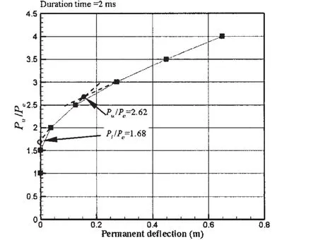
Fig.28 Peak pressure versus permanent deflection relationship of the structure for duration time of 2 ms

Based on the proportional limit,critical pressure is denoted by Pl,which is the same as permanent deflection denoted by Pu.Fig.31 shows the relationship of critical pressure and duration time.Formulae may be derived by regression analysis of the No.96 tank containment systems,as follows:where Peis the ultimate capacity of the tank containment systems,τ is the pressure pulse duration time.Although the ultimate strength of tank containment in this paper is larger than the results in Ref.[9],the critical pressure formula is similar.With the duration time increases,the critical pressure of the tank containment systems is also reduced.
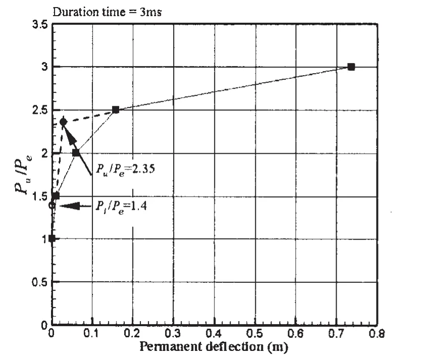
Fig.29 Peak pressure versus permanent deflection relationship of the structure for duration time of 3 ms
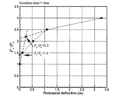
Fig.30 Peak pressure versus permanent deflection relationship of the structure for duration time of 5 ms
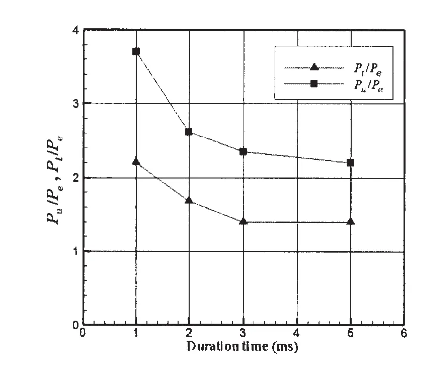
Fig.31 Relationship of critical pressure versus duration time
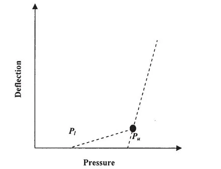
Fig.32 Relationship of permanent deflection versus critical pressure
Two types of structural safety measure basis are usually considered for design and strength assessment of structures,namely,allowable stress method and limit state methods.For the former basis,the design is carried out so that the applying stress should not be larger than the allowable stress.While the applying stress can be calculated by the methods of structural mechanics,the allowable stress may be defined with some fractions of material yield stress based on past experience,although it is not always straightforward to define the relevant allowable stress value.For the latter basis,the measure of structural safety is evaluated as a ratio of the ultimate capacity to the applied load.As the duration time of sloshing impact known,the ultimate capacity can be defined as a critical load,where Pland Puare considered shown in Fig.32.To be safe,the following criteria should be satisfied:

where σais the allowable stress of tank containment systems structures under sloshing,σwis the applying stress of tank containment systems structures under sloshing,Plis the ultimate capacity of structures under sloshing based on proportional limit,Puis the ultimate limit capacity of structures under sloshing,Peis the peak pressure,ηais safety factors corresponding to the allowable stress method,ηlis safety factors corresponding to the proportion of limit state method,ηuis safety factors corresponding to ultimate limit state method.
6 Conclusions
In this paper,ultimate capacity and dynamic responses of the No.96 type tank containment systems structures of large LNG carriers are studied using nonlinear finite element method,and design criteria and safety assessment of tank containment systems structures are analyzed.The conclusions can be drawn as follows:
(1)The failure mode of tank containment systems structures under quasi-static pressure loads is that the lateral girders of the secondary box structure have been buckling firstly,which leads to the damage of the whole structures.The boundary condition of the top plywood of the box structure is dealt with simply supported.
(2)When the duration time is fixed,the plastic deformation of tank containment systems structures is increased as peak pressure.While tank containment systems structures have been elastic deformation due to less peak pressure,they have been plastic deformation or permanent deflection as larger peak pressure.When the load is fixed,the permanent deflection of tank containment systems structures is increased as duration time of sloshing with different failure mode.It is seriously damaged that the top plywood of the box structure due to shorter duration time,as the lateral girders of the secondary box structure have the biggest deformation in longer duration time.
(3)Sloshing impact characters should be considered in design and safety assessment of tank containment systems structures.
[1]Bass R L,Bowles E B,Cox P A.Liquid dynamic loads in LNG cargo tanks[J].Trans SNAME,1980,88:103-126.
[2]BV.Sloshing damages known dada-partial fillings analysis[S].BV Technical Note,1999.
[3]Wang Deyu,Jin Xianding,Li Longyuan.On model experiment of sloshing in tanks[J].Journal of Shanghai Jiao Tong University,1998,32(11):114-117.
[4]Zhu Renqing.Time domain simulation of liquid sloshing and its interaction with flexible structure[D].Ph.D.Thesis.Wuxi:China Ship Scientific Research Center,2001,B2001-02-04.
[5]Qi Jiangtao,Gu Min,Wu Chengsheng.Numerical simulation of sloshing in liquid tank[J].Journal of Ship Mechanics,2008,12(4):574-581.
[6]Zhao Wenhua,Hu Zhiqiang,Yang Jianmin,et al.Investigation on sloshing effects of tank liquid on the FLNG vessel responses in frequency domain[J].Journal of Ship Mechanics,2011,15(3):227-237.
[7]Valsgard S,Tveitnes T.LNG technological developments and innovations-Challenges with sloshing model testing[R].Det Norske Veritas AS Paper Series,No.2003-P005.
[8]ABS.Strength assessment of membrane-type LNG containment systems under sloshing loads[S].ABS Guidance Notes,2006.
[9]Paik J K.Limit state design technology for a membrane type liquid natural gas cargo containment system under sloshing impacts[J].Marine Technology,2006,43(3):126-134.
[10]ISSC.Report of Committee I.2:Loads[C]//Proc of 16th International Ship and Offshore Structures Congress.St John’s,2006,1:87-179.
[11]ISSC.Report of Committee II.2:Dynamic response[C]//Proc of 16th International Ship and Offshore Structures Congress.St John’s,2006,1:267-367.
[12]Qi Enrong,Xu Chun,Wang Xueliang,et al.Report of model experiments of sloshing in a tank of a large LNG carrier[R].Wuxi:China Ship Scientific Research Center Report,2010.
[13]Qi Enrong,Pang Jianhua,Xu Chun,et al.Experimental study of sloshing pressure and structural response in membrane LNG tanks[J].Ship Science Technology,2011,33(4):17-24.
[14]Qi Enrong,Zhang Xiaojie,Teng Bei,et al.Study of ultimate hull girder strength of large liquefied natural gas carriers[J].Journal of Ship Mechanics,2010,14(1-2):66-73.
- 船舶力学的其它文章
- Activities of Propulsion Design and Cavitation Test for Merchant Ships in CSSRC
- 3D Trajectory Tracking Control Platform Design for Deep Sea Open-framed Remotely Operated Vehicle based on Hydrodynamics Test
- Quasi-static Compressive Behavior of U-type Corrugated Cores Sandwich Panels
- Research of Repair Major Joint Cracks of Offshore Platforms by Finite Element
- An Application of Homogeneous Matrix Method of Multi-body System to the Dynamic Response of Floating Bridge
- Theoretical Studies in Isolated Prop Model of Subsea Pipeline

