Research of Repair Major Joint Cracks of Offshore Platforms by Finite Element
ZHOU Hong,SHI Wen-qiang,ZHANG Yuan-yuan
(1 School of Naval Architecture,Ocean and Civil Engineering,Shanghai Jiao Tong University,Shanghai,200240,China;2 School of Naval Architecture and Ocean Engineering,Jiangsu University of Science and Technology,Zhenjiang 212003,China)
1 Introduction
The ocean platforms are long-term used in the harsh environment,undergoing the alternating environmental loads such as wind,waves,current,ice and earthquake.These external loads and the structural resistance have uncertainties in some degree due to randomicity of waves and uncertainties of member’s size,material characteristics and various degradations,etc[1-3].Therefore the structure of platforms inevitably has various forms of fatigue cracks,which will result in fatigue failure,being the most pervasive types of structural problem.In recent years,many efforts have been put on the repair and reconstruction of cracks[4-5].
Liu et al(2002)[1]studied the traditional method to repair steel structure fatigue cracks,which is usually to polish the cracks or to repair welding underwater.The crack polish only suits in the shallow surface cracks,but the submarine patching will have the damage and additional stress to the original structure[6].Chen et al(2008)[7]addressed using the steel structure for reinforcement can overcome the shortcoming of welding thermal load,which is set up by the traditional repairing method,where there is the good application prospect in the sea old age structure repairing aspect.Lin et al(2008)[8]applied the finite element submodelling method and fracture mechanics theory to study the surface cracks of joints for aging platforms,using ANSYS software described the detailed local stress distribution.
Owing to the aging problem of the existing offshore platforms and the lack of the continued safety management of structures during their lifetime,it is necessary to develop mathematical tools to repair and reconstruct the cracks in field conditions.This paper covers the Finite Element Analysis for joint of major structure for offshore platform.The joint is located on elevation of(+)69.0 ft on cellar deck of topside of platform.Because there have been cracks around the joint,to get the influence of the cracks,Finite Element Analysis with ANSYS program has to be performed.
2 Model descripition
The analytic model is based on HZ 32-2 Platform of CACT Operators Group,and it is located in 354 ft depth of water approximately 250 miles Southeast of Guangzhou,China.
A topside structrure is used to simulate the platform,thus 3-D space finite element models have been generated in ANSYS 10.0.Then,boundary conditions at support points have to be simulated in order to arrive at the realistic estimate of forces and stressed in the members.
The translations in the nodal x,y,and z directions and rotations about the nodal X,Y,and Z-axes of these joints are obtained from SACS IV output report in Topside Structure In-place Analysis Platform Reassessment,and are input as loadings.The detail location of this joint is as shown in Fig.1.The input loads are applied on center points and transferred to the circumferences of the pipes through rigid regions defined by the command/CERIG in ANSYS 10.0.The command generates constraint equations based on small deflection theory.
The center points are meshed by element type MASS21.MASS21 is a point element having up to six degrees of freedom:translations in the nodal x,y,and z directions and rotations about the nodal x,y,and z-axes.A zero mass and rotary inertia are assigned to each coordinate direction.The pipes are meshed by element type SOLID45.

Fig.1 Detail location of joint
3 Finite Element Analysis
3.1 Model without cracks
The coordinates of keypoints in ANSYS model come from SACS model and modified as per the existing as-built drawing,listed in the Tab.1.

Tab.1 Key point coordinate
In order to describe the detail of the model,the paper lists the dimensions of chord,H-beam and brace.The diameter of chord is 54 inch,the thickness of upper chord at point 8557 is 1.75 inch,while the lower chord at point 8385 is 2.25 inch.As for the brace located at both sides of the chord,the diameter is 24 inch,with the thickness at point 8376 is 0.625 inch and at point 8393 is 0.75 inch.
Here points out two types of H-beam showed in the Fig.2.One type is at point 8506 and 8555,the thickness of panel is 0.25 inch and the width is 18 inch,besides the thickness of web is 0.625 inch.The other one is at point 8549 and 8558,increased with the thickness of panel to 1 inch,while the width of panel and the thickness of web keep the same as the former.
In addition,the thickness of added rings located in the joint area of the panel of two H-beams is 0.5 inch.
Model plots are shown in the Fig.2,with the detailed dimensions marked.

Fig.2 Model plots
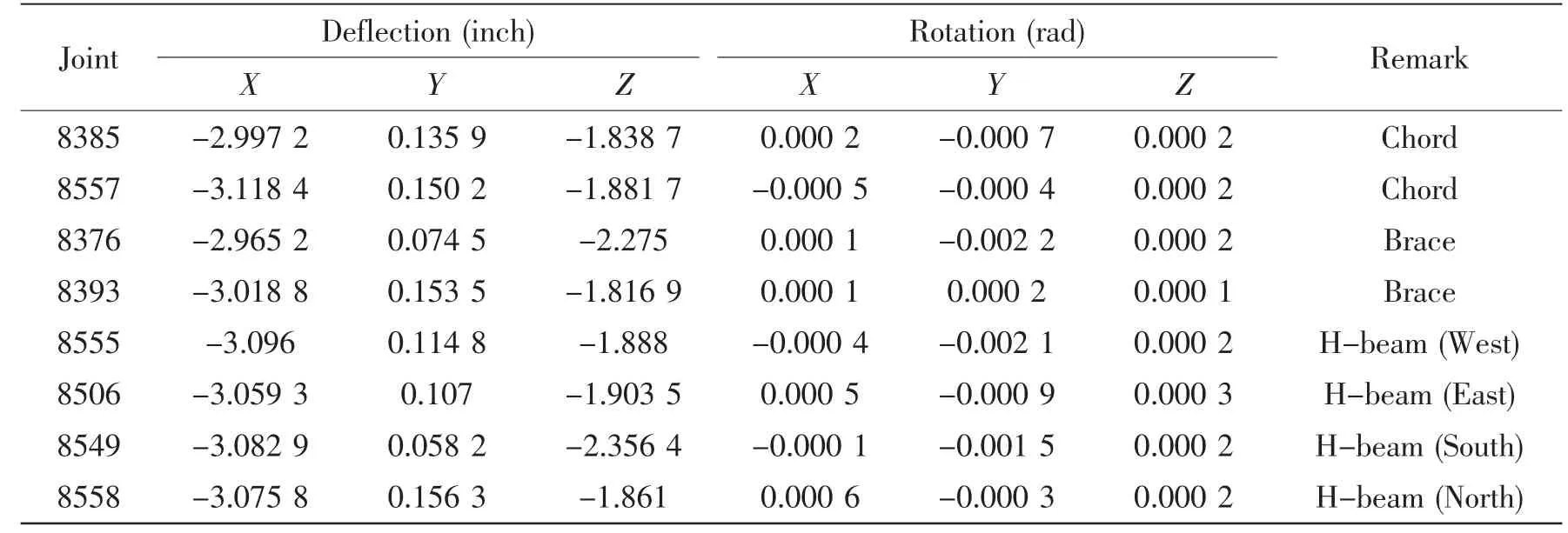
The joint deflections and the unity check of joint in different load cases are shown in the Tab.2 and Tab.3.The forces applied to the joints are calculated from deflection with ANSYS Program.
3.2 Model with cracks
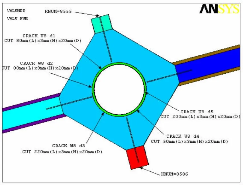
The model is the same as Fig.2,except the cracks are modeled by cutting 3 mm(height)×20 mm(depth)with different length.The crack information comes from the inspection reportperformed by SC Jenhope limited,shown as Fig.3 and Tab.4

Tab.2 Joint deflection and rotation

Tab.3 Joint end force in global

Fig.3 The crack of joint

Tab.4 The crack information of joint
Model plots with cracks are shown in the Fig.4.There are five cracks that with the same height and depth,marked the crack ID d1,d2,d3,d4 and d5.The length is taken 80 mm,80 mm,220 mm,50 mm and 200 mm,separately.
3.3 Model reinforced
The model is based on the original model shown as Fig.2,except the model is reinforced with brackets.
The brackets that are used to reinforce the structure installed on the topside of chord.They are rings of 0.75 inch in thickness,with the bracket plates of 0.75 inch in thickness as well,located in the joint of rings and H-beam.In addition,a stiffener was put on the edge of bracket plates to enhance the structure.
Model plots with reinforced are shown in the Fig.5.

Fig.4 Model plots with cracks

Fig.5 Model plots with reinforced
4 Result analysis
4.1 Model without crack
The calculated stress distributing diagrams are shown as Fig.6.
The maximum stress on crack location is 16.384 ksi,less than the material allowable stress(0.9×Yield stress(50 ksi)=45 ksi).


Fig.6 The calculated stress distributing diagrams without crack
From the stress diagram,the location where the max stress is 16.384 ksi on the chord is the area of stress concentration.It would be the easiest to crack.Thus,it should add the cracks here for the analysis of model with crack.
4.2 Model with crack
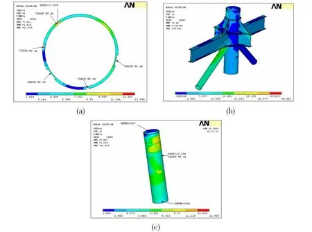
The calculated stress distributing diagrams are shown as Fig.7.
The maximum stress on crack location is 22.314 ksi less than the material allowable stress(0.9×Yield stress(50 ksi)=45 ksi).

Fig.7 The calculated stress distributing diagrams with crack
As shown in the Fig.7(c),after adding the cracks on the structure,the max stress of the original stress concentration joint for the chord has increased greatly later on.In contrast,the stress of joint in any other locations is almost the same as before,which is not under the influence of the cracks.
4.3 Model reinforced
The calculated stress distributing diagrams are shown as Fig.8.
The maximum stress on crack location is 13.938 ksi,less than the material allowable stress(0.9×Yield stress(50 ksi)=45 ksi).

Fig.8 The calculated stress distributing diagrams with reinforced
When the joint with steel structure in repaired and reinforced,the max stress of the original stress concentration joint for the chord has decreased later on,dropping down to 13.938 ksi.
The max stress in the joints of H-beam all have different degrees of reduction.Structure joint strength has been obviously improved and effect of structure repair and reinforcement is remarkable
Such way has overcome the shortcomings of traditional repair methods,while do not need to break down the compositions of the main structure joint.
4.4 Summary results
The finite element analysis results using ANSYS 10.0 are list as Tab.5.
Based on the start joint 8553 and end joint 8557,this paper analyses the Maximum Von Mises Stress of joints in three conditions,such as without cracks,with cracks and with reinforcement.According to the Tab.5,the stress of joint with cracks is 22.314 ksi,while the stress of major joint has decreased 8.376 ksi to 13.938 ksi after the reconstruction.

Tab.5 Results of the finite element analysis
5 Conclusions
Based on the presented results of the numerical analysis of the stress state of major joint cracks of offshore platforms,it is concluded that:
(1)Cracks occurrence in the elements of the original structure of offshore platform is the consequence of highly pronounced stress concentration in critical zones;
(2)Reconstruction of major joint of offshore platform structure has significantly reduced the level of stress concentration.
It is important to highlight that,based on the obtained results in FEA,the reconstruction is designed in such a way to be realized in field conditions,without dismantling offshore platform structure components.After the reconstruction the stress of major joint has decreased 8.376 ksi.Visual inspection of the slewing platform proves that there are no defects in the structure.This fact confirms the validity of the implemented approach and presents indirect proof of correctness of numerical analysis of stress state of major joint structure of offshore platforms.
[1]Ji Chunyan,Li Shanshan,Chen Minglu.A global reliability assessment method on aging offshore platforms with corrosion and cracks[J].China Ocean Engineering,2009,23(2):199-210.
[2]Wang Qingfeng,Huang Xiaoping,Cui Weicheng.Research on security life assessment and repair decision of ocean platform Structure[J].Journal of Jiangsu University of Science and Technology(NaturalScience Edition),2006,20(3):11-15.
[3]Zhang Zhaode,Wang Deyu.A study on crack detection with modal parameters of a jacket platform[J].China Ocean Engineering,2004,18(1):1-10.
[4]Newman J C,Raju I S.An empirical stress intensity factor equation for the surface crack[J].Eng.Fracture Mechanics,1981,15(2):185-192.
[5]Srđan Bošnjaka,Zoran Petkovi a,Nenad Zrni,Goran Simi a,Aleksandar Simonovi a.Cracks,repair and reconstruction of bucket wheel excavator slewing platform[J].Engineering Failure Analysis,2009,16(5):1631-1642.
[6]Liu Haitao,Liu Chuntu,Li Zhiqi,Cui Minzi,Kan Changzhen.Fatigue analysis of multiple repairing welding on high strength offshore structure steel[J].Journal of Mechanical Streng,2002,24(3):433-435.
[7]Chen Tuanhai,Chen Guoming,Lin Hong,et al.Simulation study of CFRP-based repair effect for cracked tubular joint of offshore platforms[J].China Petroleum Machinery,CPM,2008,36(10):1-4+50.
[8]Lin Hong,Chen Guoming,Chen Tuanhai.Analysis of surface crack on tubular joints for aging jacket platforms[J].Journal of Mechanical Strength,2008,30(5):814-819.
- 船舶力学的其它文章
- Activities of Propulsion Design and Cavitation Test for Merchant Ships in CSSRC
- 3D Trajectory Tracking Control Platform Design for Deep Sea Open-framed Remotely Operated Vehicle based on Hydrodynamics Test
- Quasi-static Compressive Behavior of U-type Corrugated Cores Sandwich Panels
- Structural Dynamic Response Study of Large LNG Carriers under Sloshing Impacts in Tanks
- An Application of Homogeneous Matrix Method of Multi-body System to the Dynamic Response of Floating Bridge
- Theoretical Studies in Isolated Prop Model of Subsea Pipeline

