Assessing the energy release characteristics during the middle detonation reaction stage of aluminized explosives
Kun Yang, Lang Chen, Danyang Liu, Bin Zhang, Jianying Lu, Junying Wu
State Key Laboratory of Explosion Science and Technology, Beijing Institute of Technology, Beijing 100081, China
Keywords:Aluminized explosive Non-ideal detonation Water push test Energy release
ABSTRACT Afterburning behind the detonation front of an aluminized explosive releases energy on the millisecond timescale,which prolong the release of detonation energy and the energy release at different stages also shows significant differences.However, at present, there are few effective methods for evaluating the energy release characteristics of the middle reaction stage of such explosives,which can have a duration of tens to hundreds of microseconds.The present work demonstrates an approach to assessing the midstage of an aluminized explosive detonation based on a water push test employing a high degree of confinement.In this method, the explosive is contained in a steel cylinder having one end closed that is installed at the bottom of a transparent water tank.Upon detonation, the gaseous products expand in one direction while forcing water ahead of them.The resulting underwater shock wave and the interface between the gas phase products and the water are tracked using an ultra-high-speed framing and streak camera.The shock wave velocity in water and the expansion work performed by the gaseous detonation products were calculated to assess the energy release characteristics of aluminized explosives such as CL-20 and RDX in the middle stage of the detonation reaction.During the middle stage of the detonation process of these aluminized explosives, the aluminum reaction reduced the attenuation of shock waves and increased the work performed by gas phase products.A higher aluminum content increased the energy output while the presence of oxidants slowed the energy release rate.This work demonstrates an effective means of evaluating the performance of aluminized explosives.
1.Introduction
Aluminized explosives are widely used in military and civilian applications because of their excellent blast effect and underwater performances,however,the complex chemical reactions occurring during the detonation of these materials can lead to low detonation velocities and pressures in addition to wide detonation reaction zones [1-3].The components of these explosives, including aluminum and oxidizers, can also continue to react after the CJ plane, known as the afterburning effect [4,5].This effect can prolong the release of detonation energy and may be modified by confinement, such that the energy release mechanism becomes more complicated.For these reasons, detailed analyses of energy release from the detonation of aluminized explosives remain challenging.Previous studies have primarily used metal plate acceleration[6-12]and underwater tests[13-16]to study the energy release associated with detonations.In the case of the former tests,the velocity of a metal plate driven by a detonation is determined using high-speed scanning photography or laser interferometry[17].Manner et al.conducted cylinder tests to compare the metal acceleration characteristics of HMX-based aluminized and LiFcontaining explosives, and found that the energy released by the reaction of aluminum in these materials promoted the expansion of detonation products and so improved the working ability of the explosives[4].Li et al.[5]studied the effects of the quantity and size of aluminum particles on the workability of RDX-based aluminized explosives using cylinder tests and reported that 15% aluminum gave the best performance.Because the explosive is only minimally constrained during a cylinder test,the gaseous detonation products are able to expand rapidly such that the pressure of these gases quickly decreases,which is not conducive to ensuring the complete reaction of the aluminum in the formulation.On this basis,Liu et al.[18,19] designed a confined plate push test to assess the effects of the amount and size of aluminum particles on the workability of CL-20-based aluminized explosives.Aluminum was found to primarily react with detonation products after the CJ plane and smaller aluminum particles were observed to react earlier and more rapidly, leading to a greater energy output.However, the metal cylinders and plates used in such tests typically ruptured within a time span of tens of microseconds after the detonation.As such, the velocity of these items after that point no longer accurately reflected the working ability of the detonation products.Therefore, only the energy release characteristics of the early reaction stage can be obtained from such tests.
In the case of free-field deep water explosion tests,the gaseous detonation products are confined by water and this can allow the aluminum to react more completely with the detonation products.Thus,this technique is better suited to the analysis of energy release from aluminized explosives.Bocksteiner et al.[20] carried out underwater explosion tests of an RDX-based aluminized explosive containing an oxidizer (PBXW-115) and measured the shock wave pressure.The pressure data were used to analyze the energy output by calculating both the underwater explosion shock wave energy and bubble energy.Underwater explosion tests by Xiang et al.[13]showed that the incorporation of an oxidant can promote the reaction of aluminum and release more energy.Hu et al.[14] found that the underwater detonations of explosives containing nanoaluminum powder generated greater shock wave pressures but lower bubble energies.The energy release characteristics of explosives as assessed using underwater tests are typically analyzed by measuring the shock wave pressure in the far field and so primarily reflect aspects of the later stage of detonation.Miller et al.[21] designed an experiment in which the explosive was confined in a block of steel in all directions except one, such that the detonation products could expand in that direction while pushing water along a thick transparent tube.The motion of the interface between the gaseous products and the water was tracked using a framing and streak camera to allow an investigation of the energy release.However, this test used a very small explosive mass of approximately 0.5 g such that the aluminized explosives may not have reached a stable detonation state.In addition,the transparent tube tends to rupture after a short time span so that it is difficult to analyze the energy release of the explosive over longer durations.
Because of the limitations described above, it is challenging to assess the energy release kinetics associated with the detonation of aluminized explosives throughout the entire detonation duration using a single test [22].Although metal acceleration and underwater explosion tests can analyze the energy release in the first tens or hundreds of microseconds after the detonation of an aluminized explosive,respectively,effective methods of evaluating the middle reaction stage, ranging from tens to hundreds of microseconds,remain elusive.
This paper reports a means of evaluating the energy release properties of aluminized explosives during the mid-stage of the detonation process, based on a water push test with significant confinement of the energetic material.In this process,the explosive is confined in a steel cylinder with one end closed.This high degree of confinement allows the material to detonate in a stable manner such that the aluminum can fully react.The steel cylinder is installed at the bottom of a transparent water tank so that the detonation products expand in one direction while pushing water.The underwater shock wave and the interface between the gaseous reaction products and the water are tracked using an ultra-highspeed framing and streak camera.Based on calculating the shock wave velocity in water and the expansion work performed by gaseous detonation products, the energy release characteristics in the middle stage of the detonation of CL-20 and RDX based aluminized explosives reaction were analyzed.
2.Confined water push test
Afterburning behind the detonation front of an aluminized explosive prolongs the duration of energy release to the millisecond timescale.Fig.1(a)presents a diagram showing the process by which an aluminized explosive undergoes detonation.A detonation is often defined as a violent chemical reaction during which a detonation wave propagates through the explosive material[23].According to classical detonation theory, the process can be described using the Zeldovich-von Neumann-Doering model[24].The detonation wave is composed of a shock wave front and a subsequent continuous reaction zone, at the end of which is the Chapman-Jouget (CJ) plane.In the case of an ideal explosive, the material reacts completely prior to the CJ plane and the energy released by this process helps to propagate the detonation wave.In addition, isentropic expansion is assumed to occur after the CJ plane.However, aluminized explosives contain aluminum powder and,often,oxidant and so significant afterburning can occur during the detonation.After the CJ plane, the aluminum and oxidant can continue to burn throughout the expansion of the detonation products to release a large amount of energy.Therefore, only by evaluating the energy output of aluminized explosives in different stages can the energy release characteristics of the entire detonation process be obtained.
The early stage of a detonation, having a duration of tens of microseconds, involves the onset of the reaction of the aluminum powder in the formulation.In the case of a confined plate test, as shown in Fig.1(b)[18,19],the expansion of the gaseous detonation products is constrained such that a high pressure environment is generated that promotes the release of energy from the reaction of aluminum particles.Thus,this technique allows the energy release during the early stage of the detonation to be evaluated.In the later stage of the process, after the detonation products have expanded over a duration of hundreds of microseconds, the explosive has fully reacted and the energy release is complete.Hence, free-field underwater explosion tests can be used to analyze the total energy output characteristics[13-16,20,25],as shown in Fig.1(d).The compressibility and flowability of water can be used to contain the gaseous detonation products over a prolonged time span.This scenario avoids issues associated with the fragmentation of metal plates or cylinders.Even so, because of a present lack of effective measurement methods, existing underwater explosion test methods cannot be used to analyze the mid-stage energy characteristics of a detonation.Hence, the present work provides a new technique based on using a water push test to evaluate highly confined detonations,as shown in Fig.1(c).
Fig.2 provides a diagram of the experimental apparatus used to perform the confined water push tests in this work.This system primarily comprised a confined water push device, an ultra-highspeed framing and streak camera and a xenon lamp.The explosive charge was composed of a booster and a quantity of the explosive being tested,both placed in a steel confinement chamber,as shown in Fig.3.One end of the chamber was closed and the steel cylinder was installed at the base of a transparent water tank such that the detonation products expanded in one direction while forcing the water to move in the same direction.The explosive was coated with a silicone vacuum grease to ensure close contact with the interior of the cylinder.The water tank was rectangular and open at the top,with transparent poly(methyl methacrylate) sides and a steel plate on the bottom.This tank was filled with water prior to each test.The booster used to detonate the explosive was installed at the closed end of the cylinder and a trigger probe was attached to the side of the booster.This probe initiated the camera and xenon lamp at the moment of detonation.During detonation,the gaseous products reacted with the aluminum particles in the formulation and expanded while confined within the steel cylinder.Shock waves were generated in the water and the expansion of the detonation products forced the water to move in a specific direction.As the high-density shock wave front moved through the water, the refractive index of the water was changed resulting in refraction.The gaseous detonation gas products also blocked the transmission of light through the water.The xenon lamp was positioned on one side of the tank for illumination while the camera was positioned on the other side to track the shock wave and the interface between the gas phase products and the water.These data were then used to analyze the propagation of the shock wave and the expansion rate of the gaseous products.
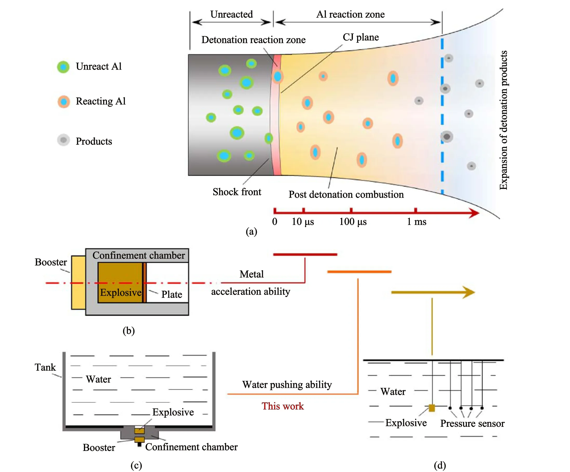
Fig.1.A diagram summarizing the non-ideal detonation of an aluminized explosive and a method of evaluating the energy release characteristics of such explosives at different detonation stages: (a) Non-ideal detonation; (b) Confined plate push test; (c) Confined water push test; (d) Underwater explosion test.
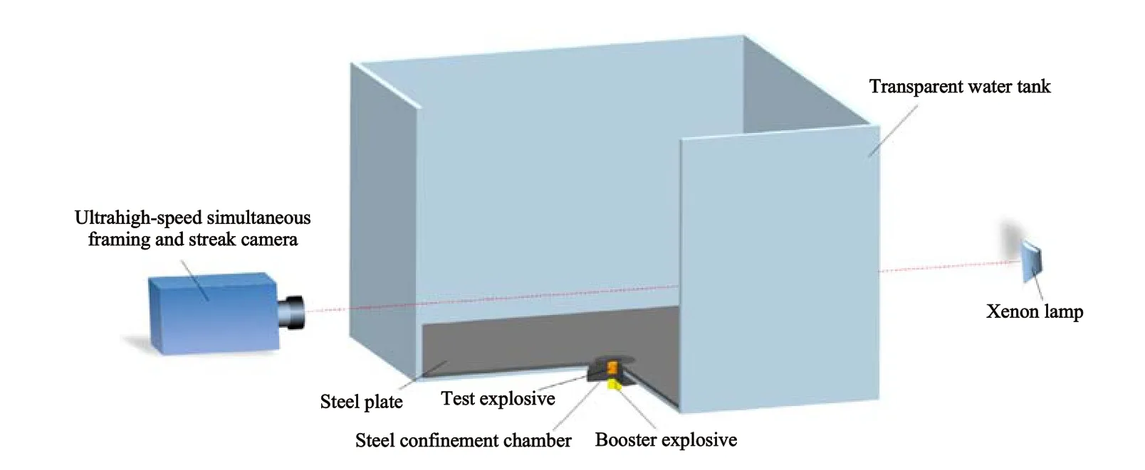
Fig.2.Diagram of the experimental setup for the confined water push tests.
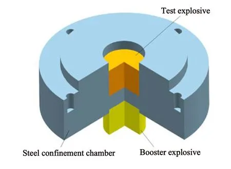
Fig.3.Diagram of the confined charge.
In each test, the diameters of both the explosive charge and booster were 20 mm and JO-9159 was used as the booster material.The outer diameter of the steel cylinder was 80 mm, the inner diameter was 20 mm, the depth was 20 mm and the thickness of the closed end was 8 mm.The cylinder also incorporated a 10 mm wide and 6 mm high step with four threaded holes.The length and width of the transparent water tank were both 600 mm and the water depth was 400 mm.As noted,the steel cylinder was installed at the bottom of the tank.The camera used in this work was able to capture eight frame and trajectory images and the time interval between each frame could be adjusted independently with a resolution on the nanosecond scale.The time range over which trajectory monitoring could be performed was 0.5 ns-500 μs and the minimum time resolution associated with this monitoring was on the picosecond scale.
Using the above experimental equipment, water push tests of highly confined CL-20 and RDX-based explosives were carried out.In each case,the underwater shock wave and the interface between the gas phase products and the water were tracked such that the energy release characteristics of these aluminized explosives in the middle stage of the detonation reaction could be analyzed.The energy release characteristics of RDX/LiF/Wax and trinitrotoluene(TNT) samples were also analyzed for comparison.Table 1 summarizes the compositions of the explosive samples together with physical properties of these materials.The particle size in aluminized explosives was about 15 μm.The detonation velocity and pressure values provided here were determined using probes and manganin sensors, respectively [19].The detonation velocity and pressure data for RA15 and RF15 were obtained from Ref.[25].The explosive heat of all test explosives were calculated using the EXPLO5 software package[26].
3.Results and discussion
3.1.Flow field characteristics
Fig.4 presents images showing the propagation of shock waves in water and the expansion of gaseous detonation products at different times after the detonation of a CA25 sample.The shadow having a circular arc in this figure indicates the propagation of the shock waves through the water.The black elliptical area at the bottom of the figure indicates the expansion of the opaque gaseous products and corresponds to the bubble generated by the expansion of these products at that moment.The shock wave can be seen to be semi-circular and the propagation radius of this wave gradually increases with time while the bubble generated by the expansion of the gas phase products is semi-elliptical.The longest time span captured by the camera in this study was 200 μs,which was sufficient to monitor the propagation of shock waves and gas phase products and so assess the energy output characteristics in the mid-stage of the detonation.
Fig.5 shows the trajectories of the shock wave propagation and gas phase product expansion in the water following the detonation of a CA25 specimen.The inclined trajectory from the lower left corner to the upper right corner indicates the movement of the shock wave while the motion of the black area at the bottom of the figure indicates the trajectory of the gas phase products.Because the slit in the test apparatus through which images were acquired was aligned with the centerline of the water tank,these trajectories correspond to continuous changes in the positions of the semicircular shock wave front and the semi-ellipsoidal bubble boundary vertex.The total monitoring time during each experiment was 103 μs and there was a 27.1 μs delay in acquiring images,such that image capture ceased 130.1 μs after initiation of the detonation.Therefore,the time corresponding to the leftmost end of the image shown in Fig.5 is 27.1 μs while the rightmost end corresponds to 130.1 μs.The two trajectory lines obtained through such images were used to determine the radius of the semi-circular shock wave front and the semi-axis length of the elliptical bubble for each trial.It should also be noted that the slope of the trajectory was equivalent to the velocity of the wave front or bubble.It is apparent from the image in Fig.5 that the shock wave front in the water was always located above the bubble boundary and that the slope of the shock wave trajectory was greater than that of the bubble boundary trajectory.These results indicate that the speed of shock wave propagation in the water was much higher than the speed of bubble expansion.The trajectory of the shock wave propagation changed almost linearly with time, suggesting that the shock wave propagation rate remained relatively constant.In contrast,the trajectory of the bubble expansion exhibited a parabolic shape,meaning that the speed of bubble expansion gradually decreased.This decrease occurred because the pressure inside the bubble gradually decreased over time.Trials using RA15, RF15, RA30 and TNTsamples showed that the shock wave propagation and gaseous products expansion were similar to those of the CA25.

Table 1 Compositions and physical properties of the explosive specimens.
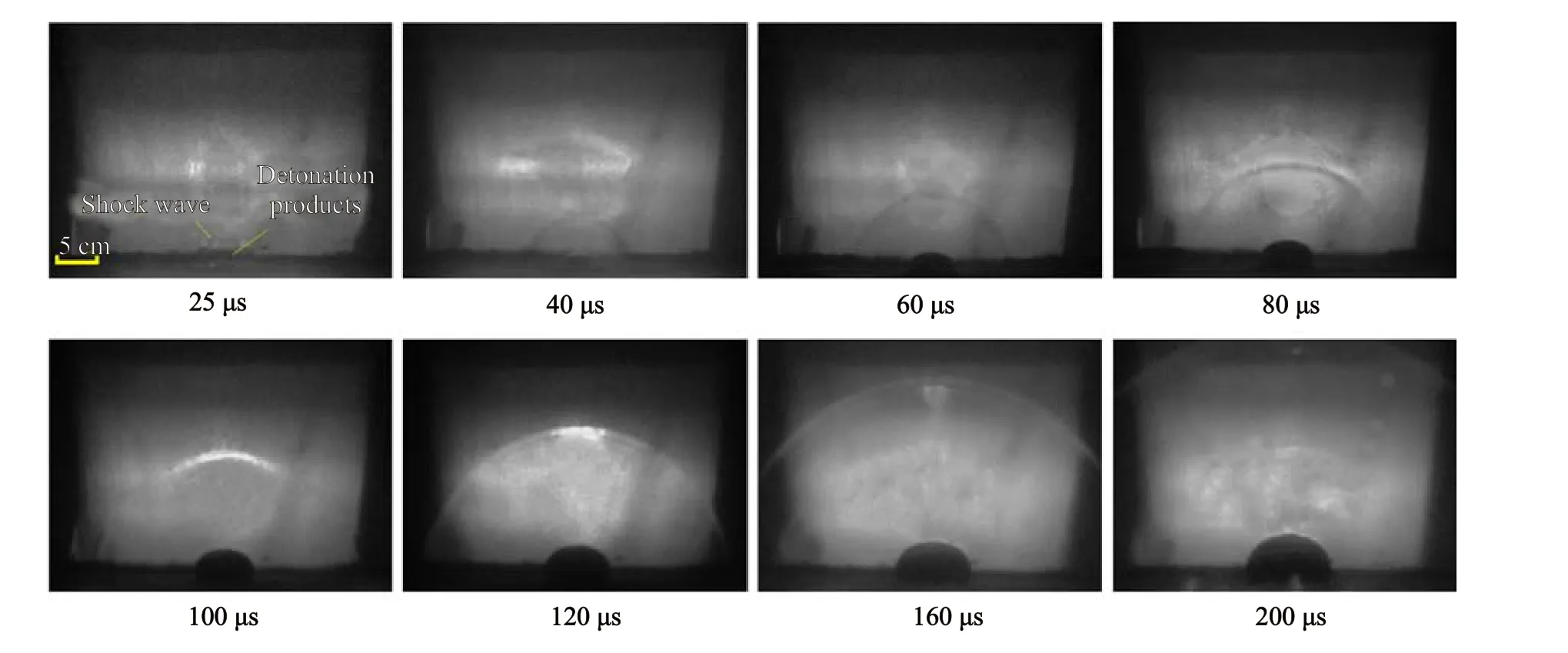
Fig.4.Images showing the propagation of shock waves and the expansion of gas phase detonation products in water at different times after the detonation of CA25.
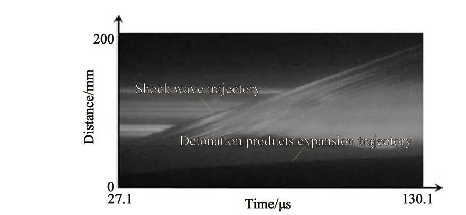
Fig.5.The trajectories of shock wave propagation and gas phase product expansion in the water tank.
To identify the position of the shock wave front in water and the contact boundary between detonation products and water from the photos shown in Figs.4 and 5,the Digimizer software package was used.Before the formal dynamic experiment,we first took a static image of a 60 mm×60 mm square to determine the actual size of each pixel in the image.By using Digimizer, the boundary information of the image is automatically recognized based on the critical value of grayscale change.Due to the limitations of image pixels, the recognition accuracy we selected only reached 0.1 mm,with an error of ±0.1 mm.
3.2.Shock waves characteristics in water
Fig.6 shows the shock wave flow field images obtained from trials with the CA25, TNT, RA30, RF15 and RA15.In each case, the propagation of the shock waves and the expansion of the gas phase products are quite similar.The shock wave propagation distances at different times are indicated.At 40 μs, the distances for the CA25,TNT,RA30,RF15 and RA15 were 63.2 mm,78.6 mm,79.5 mm,82.6 mm and 85.4 mm, respectively, while at 160 μs these values were 242.5 mm, 265.6 mm, 266.6 mm, 267.1 mm and 277.1 mm,respectively.Thus, the shortest shock wave propagation appeared in the case of the CA25 and was increased by 179.3 mm between 40 and 160 μs.The distances propagated by the TNT and RA30 shock waves were approximately equal, with the maximum relative deviation in distance at different times being 1.15%.In trials with these materials, the propagation distances increased by 187 mm and 187.1 mm, respectively, between 40 μs and 160 μs, indicating similar shock wave propagation rates in water for these two explosives.This may be the aluminum particles did not participate in the reaction during the initial stage of explosive detonation,resulting in less initial energy release.The shock wave generated by the RA15 was significantly faster such that the distance increased by 191.7 mm on going from 40 μs to 160 μs.It should be noted that the RF15 explosive incorporated unreactive LiF in place of the aluminum used in the RA15.The shock wave propagation distance for the RF15 was less than that of the RA15 at the same time,indicating that the reaction of aluminum powder may reduce attenuation of the shock wave in water.
Fig.7 summarizes the shock wave propagation distances in water associated with the different explosives.A straight line has been fitted to each of these data sets to quantify the relationship between propagation distance and time for each, and the slope of this curve can be considered to equal the average propagation velocity.The values calculated for the CA25, TNT, RA30, RF15 and RA15 explosives under the same conditions were 1498 m/s,1601 m/s,1569 m/s,1570 m/s and 1607 m/s,respectively.In the case of the CA25,RA30 and RA15,In the case of the CA25,RA30 and RA15,we can see that the RA15 detonation produced a higher shock wave velocity than that of RA30, indicating an increase in aluminum content and a decrease in shock wave velocity in water.Compared with RA15 and RF15,when Al was replaced by inert LiF,it also leads to a decrease in shock wave velocity in water.For CA25,the content of CL-20 in mixed explosives is only 30 wt%, corresponds to the lowest underwater shock wave velocity.The above phenomenon can demonstrate to us that the underwater shock wave velocities were closely related to the aluminum particles’heat absorption and reaction.During the initial stage of detonation,aluminum particles absorb a large amount of heat as inert substances,and the reaction of aluminum particles is highly dependent on high-temperature and high-pressure environments.Thus, aluminum particles in RA30 absorb more heat and slow down their own reactions,resulting in a lower shock wave velocity for RA30 than that for RA15.For RF15,LiF always remains inert,and its underwater shock wave velocity is slightly lower than RA15.For CA25, the relatively low CL-20 content and high aluminum and oxidizer contents, and aluminum particles and AP absorb more heat released by the reaction of CL-20,resulting in lower detonation pressure and velocity,which is more unfavorable for aluminum particle reaction to release energy,resulting in slower underwater shock wave velocity.
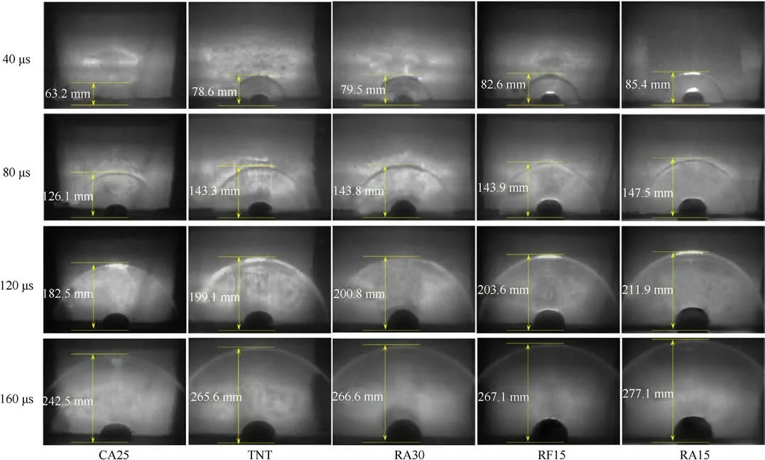
Fig.6.Flow field images of shock waves generated by different explosives at various times intervals.
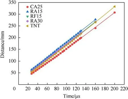
Fig.7.Shock wave propagation distances as functions of time for various explosives following detonation in water.
3.3.The working ability of detonation products
As noted, the confined charge was situated at the bottom of a transparent water tank.Following detonation of the explosive,the gaseous products expanded such that the water was moved.The size of the gas phase bubble generated in the tank was related to the rate of expansion of the detonation products and reflected the ability of these products to push the water.Hence, this test provided information regarding energy release characteristics.Fig.8 plots the lengths of ellipsoidal bubbles along the semi-axis as functions of time during the expansion of gas phase products following the detonation of each explosive, as obtained from the captured images.The solid lines in the figure represent the fitting of exponential functions to the data.In each case, the correlation coefficient for this fit exceeded 0.99,indicating that these data were well described using exponential equations.Fig.8 demonstrates
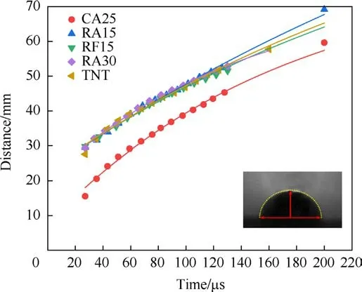
Fig.8.The semi-axis lengths, b, of the ellipsoidal expansion of gaseous detonation products of different explosives as functions of time.
b
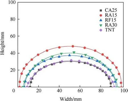
Fig.9.The sizes of the bubbles formed by detonation products from the various explosives during expansion in water after 120 μs.
athat, at a given point in time, the semi-axis length of the bubble generated by the CA25 was smaller than those of the other four explosives.It appear that the expansion of the CA25 gas phase products was slower and therefore had a relatively weak ability to drive water movement.The slope of the line describing the CA25 data is also greater than those for the other four samples.Hence,the aluminum powder reaction appears to have provided a sustained energy release during the expansion process to increase the ability of the charge to perform work.
Fig.9 shows the sizes of the bubbles formed by detonation products from the various explosives during expansion in water after 120 μs.In this work, an implicit method was used to fit the boundary of the bubbles to obtain an equation describing each elliptical boundary and the solid lines in this figure represent the fitted boundaries.It can be seen that the bubble boundaries are well described by the elliptical equations.As such,the semi-axis lengths could be obtained based on the fitting results.The work performed by the detonation products could be calculated as [27].
where Vbubbleis the bubble volume and P0is the pressure at the bottom of the water tank.The volume of a semi-ellipsoidal bubble was calculated using the formula Vbubble= 2a2b/3, where a and b are the semi-axis lengths of the ellipse equation,as the existence of deviations, the central value was used in the calculation.
Table 2 summarizes the semi-axis lengths of the bubbles obtained from the different explosives and the work done by the expansion of the detonation products.Because of the pulsation of these bubbles in water and the various boundary effects, the upward expansion velocity of each bubble was generally lower than the lateral expansion velocity.Hence,the bubbles formed by the gas phase products were ellipsoidal.In addition, a higher internal pressure could cause the bubbles to expand upwards more rapidly.Therefore, this work evaluated the ability of the detonation products to propel water based on the ratio of the two semi-axes of the elliptical bubbles.A larger ratio indicated more rapid upward expansion and so a higher internal pressure.This scenario also suggested that the post-combustion reaction of gas phase products was more intense.These data confirm that the RA15 provided the longest bubble axis while that of the CA25 explosive was the shortest.The b-axis lengths of the bubbles obtained from several of the explosives were also longer than the a-axis lengths and this table also provides the axis ratio for each sample.These results show that, at 120 μs, the b/a ratio decreased in the order of RA30 >RA15 >TNT >RF15 >CA25.Comparing the RA15 and RF15 values demonstrates that the reaction of aluminum powder significantly enhanced the explosive’s ability to drive water.Under these highly constrained conditions, the RA30 exhibited the greatest capacity to push water while the CA25 was the weakest explosive.It is apparent that the ability of the aluminized explosives with oxidants to push water was lower than that of the TNT.Table 2 also gives the work done by the expansion of the gas phase products at 120 μs.The RA15 trial evidently performed more work than that obtained from the RF15 while the work done by gas phase products generated by the RA30 was slightly lower than that of the RA15 explosive and the work done by the CA25 products was the lowest.
The results above provide information concerning the energy release characteristics of these aluminized explosives during these trials.A comparison of the data for the RA15 and RF15 shows that the reaction of aluminum in the mid-stage of the detonation can increase the work done by gaseous product expansion.A comparison of the RA15 and RA30 trials confirms that a higher aluminum content reduces the work performed.However, the elliptical bubble was relatively large, indicating that significant residual energy release could still occur in the mid-stage of the detonation reaction,with a greater potential for additional work.In contrast, the CA25 contained higher proportions of aluminum and oxidizer but the expansion of the gaseous products from this material performed less work and a lower bubble axis ratio was observed during the mid-stage of detonation.This may be due to the relatively low CL-20 content and high aluminum and oxidizer contents, where aluminum and the oxidizer do not participate in the initial reaction and absorb a large amount of heat released by the CL-20 reaction.Thus, the release of energy from the aluminum reaction was relatively slow, leading to inhibited bubble expansion and a lower ability to drive water movement at this stage.
4.Conclusions
A new method for evaluating energy release characteristics during the mid-stage of an aluminized explosive detonation was devised, based on a water push test involving a highly confined sample.This technique ensures the stable detonation of small charges and provides more complete reaction of the aluminum powder.The underwater shock wave and the interface between thegas phase products and the water were tracked using an ultra-highspeed framing and streak camera.By calculating the shock wave velocity and the expansion work of gaseous detonation products,the energy release characteristics of aluminized explosives in the middle stage of detonation could be analyzed.The reaction of aluminum during the mid-stage of detonation was found to reduce the attenuation of shock waves and increase the work of detonation products.A higher aluminum content was determined to provide a greater energy output while oxidants slowed the energy release rate.This work shows an effective approach to assessing the performance of aluminized explosives.

Table 2 Bubble semi-axis lengths for the various explosives and the work performed by the expansion of gaseous detonation products.
Declaration of competing interest
The authors declare that they have no known competing financial interests or personal relationships that could have appeared to influence the work reported in this paper.
Acknowledgments
This work was supported by the National Natural Science Foundation of China (Grant No.11832006).
- Defence Technology的其它文章
- Explosion resistance performance of reinforced concrete box girder coated with polyurea: Model test and numerical simulation
- An improved initial rotor position estimation method using highfrequency pulsating voltage injection for PMSM
- Target acquisition performance in the presence of JPEG image compression
- Study of relationship between motion of mechanisms in gas operated weapon and its shock absorber
- Data-driven modeling on anisotropic mechanical behavior of brain tissue with internal pressure
- The effect of reactive plasticizer on viscoelastic and mechanical properties of solid rocket propellants based on different types of HTPB resin

