
Conceptual design of a 714‑MHz RFQ for compact proton injectors and development of a new tuning algorithm on its aluminium prototype
2024-03-09 08:52YiXingLuWenChengFangYuSenGuoZhenTangZhao
Nuclear Science and Techniques 2024年1期
Yi‑Xing Lu · Wen‑Cheng Fang · Yu‑Sen Guo,5 · Zhen‑Tang Zhao
Abstract Radio frequency quadrupoles (RFQs), which are crucial components of proton injectors, significantly affect the performance of proton accelerator facilities.An RFQ with a high frequency of 714 MHz dedicated to compact proton injectors for medical applications is designed in this study.The RFQ is designed to accelerate proton beams from 50 keV to 4 MeV within a short length of 2 m and can be matched closely with the downstream drift tube linac to capture more particles through a preliminary optimization.To develop an advanced RFQ, challenging techniques, including fabrication and tuning method,must be evaluated and verified using a prototype.An aluminium prototype is derived from the conceptual design of the RFQ and then redesigned to confirm the radio frequency performance, fabrication procedure, and feasibility of the tuning algorithm.Eventually, a new tuning algorithm based on the response matrix and least-squares method is developed, which yields favorable results based on the prototype, i.e., the errors of the dipole and quadrupole components reduced to a low level after several tuning iterations.Benefiting from the conceptual design and techniques obtained from the prototype, the formal mechanical design of the 2-m RFQ is ready for the next manufacturing step.
Keywords Compact proton injector · RFQ · IH-DTL · High gradient · Tuning
1 Introduction
Proton accelerators are widely used in medical applications, such as proton therapy [1].Several breakthroughs have been achieved in proton therapy [2–5] and proton accelerators [6–8] in China.Currently, most proton therapy facilities employ cyclotrons or synchrotrons [9].However,these facilities cannot satisfy the demands of the recently developed ultrahigh dose-rate radiotherapy (FLASH-RT)technique, which requires the delivery of a complete dose of up to 30 Gy within 100 ms [10–12].By contrast, linacs offer a faster energy modulation response and are suitable for FLASH.Injectors are an integral component of accelerators that can yield high-quality beams, thereby contributing to their excellent performance.High-gradient technology for electron accelerators has been developed for many years,and the development of compact proton injectors, particularly RFQs, is the current research focus and should be further promoted.Studies pertaining to high-gradient technology and advanced accelerators have been conducted at the Shanghai Synchrotron Radiation Facility (SSRF) [13–16].A proton linac-based therapy facility for FLASH-RT was established [17], and the S-band high-gradient accelerating structure has been designed, fabricated, and tested [18, 19].Currently, a 714-MHz radio frequency quadrupole (RFQ)for a compact proton injector has been developed, which is suitable for both synchrotrons and linacs.
A compact injector has a small diameter and can thus shorten the entire linac.Proton injectors comprising RFQs and drift tube linacs (DTLs) are typically used in proton accelerator facilities.Conventional injectors, such as the one used in the Shanghai APACTRON Proton Therapy(SAPT) facility [20, 21], are large and heavy.The 425-MHz injector housed at the SAPT, including the ion source,measures 4.5 m long.By contrast, the compact RFQ constructed at CERN can accelerate proton beams to 5 MeV within only 2 m and has a much smaller diameter [22, 23].However, the transmission efficiency of the compact RFQ is low (30%) and can only satisfy the requirements of proton therapy.Therefore, a compact RFQ for proton injectors with a relatively high transmission efficiency is proposed.Furthermore, a novel tuning method based on the response matrix and least-squares method was developed and verified using the RFQ.The elimination of dipole component errors is challenging when tuning RFQs, and this problem is more prominent in compact and more sensitive RFQs.The proposed tuning method assigns different weights to dipole and quadrupole component errors, thus allowing the dipole components to be addressed efficiently.The quadrupole and dipole component errors of the prototype are 1.39%and 2.33%, respectively, which satisfy the requirement for a stable operation.
The RFQ operates at 714 MHz, which is a quarter of 2856 MHz, and provides a transmission efficiency exceeding 60% when the input current is maximized to 6 mA.The parameter design and beam dynamics simulation of the RFQ have been completed.To test and verify the fabrication procedure and tuning algorithm, an aluminium prototype was fabricated; subsequently, a three-dimensional electromagnetic simulation of the prototype was conducted and its sensitivity analyzed.A new tuning algorithm was developed for such a compact RFQ with high sensitivity, and its application to the prototype yielded favorable results.
2 Global demands on RFQ for compact proton injector
Proton injectors are intended for proton therapy and, in the future, for broader medical applications, such as medical isotope production.Therefore, the design is expected to yield a higher beam current than that required for proton therapy,and the input current is expected to be adjustable depending on the intended applications.The beam current required for proton FLASH-RT exceeds 600 nA on average, whereas that for synchrotrons used in proton therapy is at least 2 or 3 mA to control the treatment time.Therefore, the target transmission efficiency of the injector exceeds 50% when the input current is 6 mA.Under such a high transmission level,the injector can perform well in a linac for proton therapy and can support proton FLASH-RT, thus qualifying it as an injector for synchrotrons.The injector comprises an ion source, an RFQ, and an interdigital H-mode DTL (IH-DTL)with an operating frequency of 714 MHz and a subharmonic frequency of 2856 MHz (which is the frequency at which S-band linacs typically operate).To ensure that the injector is sufficiently compact, its length should be maintained within 4 m.The layout of the proton injector is shown in Fig.1.
To achieve a compact proton injector, the RFQ must first be designed appropriately.The 714-MHz RFQ is designed as a four-vane type owing to its high frequency, because its large vanes are easier to cool than a four-rod RFQ.The RFQ measured < 2 m long and can accelerate proton beams to 4 MeV.The transmission efficiency of the RFQ should be > 50%, depending on its purpose, and the output beam length should be set to 30◦.
3 Beam dynamics simulation for RFQ design
The beam dynamics design of the compact RFQ was completed.A general design of the entire injector was accomplished to validate the application of the RFQ in a compact injector.Finally, the design of the RFQ was verified by via an error study.
3.1 High beam transmission design
The beam transmission efficiency of the injector is primarily determined by the design of the RFQ because it can be approximately 100% in the DTL owing to its high energy and weak space charge effect.An RFQ can be categorized into four sections [24]: radial matching, shaper, gentle buncher,and accelerator.In this study, the RFQ is designed based on the aforementioned classification using the RFQGen code.First, a 5-MeV RFQ measuring ~ 2.1 m long was designed.The transmission at an input current of 1 mA was > 30%.Such an RFQ can only be employed in a linac for proton therapy and would fail to support a synchrotron because of its extremely low output current.Increasing the input beam current barely increases the output current.To achieve high transmission in the RFQ, the output energy was reduced.

Fig.1 (Color online) Layout of compact proton injector
Subsequently, the RFQ energy was set to 4 MeV.Reducing the output energy considerably can reduce the length and increase the transmission efficiency; however, more energy left will remain for the downstream IH-DTL, which implies that it will be longer.A short RFQ and a long IH-DTL may result in a complex design and will likely deteriorate the beam quality at the injector exit.By adopting the general design, the length of the 4-MeV RFQ can be limited to 2 m.The beam can be bunched and focused more efficiently, and the RFQ can maintain a high transmission efficiency.Under an input current of 1 mA, the transmission efficiency can exceed 70%, which is more than twice that of the 5-MeV output energy.Consequently, the final output energy of the compact RFQ is 4 MeV.
Next, the structure was optimized and a higher input current was tested.The beam pulse length of the injector was 10 μs, and the repetition frequency was 1 kHz.The duty factor of the radio frequency (RF) power for the RFQ was 1%;therefore, the heating on the vane tips was not severe.The curvature of the vane tip over the average aperture (RHO coefficient) was 0.75.The minimum aperture of the RFQ was 0.9 mm, and the vane voltage was 65 kV.Thus, the peak surface field was approximately 1.8 times the Kilpatrick limit.The maximum modulation factor was 3, and the final synchronous phase was − 20°.These parameters were selected to achieve a high acceleration gradient without sacrificing the transmission efficiency.
The results for the RFQ with input currents of 1 and 6 mA are shown in Fig.2a (the reason for selecting 6 mA is presented in Sect.3.2).In the simulation, the rms emittance of the input beam was set as 0.02 π mm mrad for 1 mA, 0.1 π mm mrad for 6 mA, and 0.15 π mm mrad for 10 mA.The length of the RFQ cavity was 199 cm, and the transmission efficiencies were 70% and 60% at 1 and 6 mA, respectively.The transmission efficiency remained above 50% until the input beam current reached 10 mA.The primary parameters of the RFQ are listed in Table 1.
Using the parameters and structure provided by RFQGen, we recalculated the beam dynamics simulation of the RFQ using TraceWin (Fig.2b).The beam transmission was slightly lower than that yielded by RFQGen.The output phase-energy distribution of the 1-mA beam showed some blank spaces, which were caused by the low current and low emittance, and the design was verified in the complete injector, as will be presented in Sect.3.2.The energies of the particles were analyzed using data from TraceWin.The results showed that most of the particles lost at energy levels below 500 keV, and that 20.3% and 36.5% of the total particles vanished at energy levels below 100 keV under input currents of 1 and 6 mA, respectively.
3.2 Matching between RFQ and IH‑DTL
To validate whether the RFQ design satisfies the acceptance of IH-DTLs and can predict the output beam parameters of the injector, the entire injector was preliminarily designed with an IH-DTL.The Kombinierte Null Grad Struktur(KONUS) beam dynamics was selected for the IH-DTL owing to its high acceleration gradient.Different designs of KONUS beam dynamics exist [25–27].However, three main sections exist in a KONUS period: the main acceleration section (at 0°), focusing section, and bunching section.
Preliminary designs were created for different output energies (7, 8, and 10 MeV) with a high input beam current(10 mA) and low emittance (0.02 π mm mrad).These relatively extreme parameters were selected to amplify the effect of the output energy on the length, transmission efficiency,and output energy spread of the injector.
First, during the design and comparison phases, we decided to exclude any magnets between the RFQ and IHDTL, where a triplet is typically positioned, to serve as the focusing section of the KONUS period.The beams were focused precisely in the RFQ, and their envelope increased more significantly when magnets were used.Consequently,the beams departing from the RFQ were injected directly into the IH-DTL in all the designs.
Furthermore, the beams were accelerated at 0° throughout the first period, which is different from the typical design.The bunching section in the KONUS IH-DTL can reduce the bunch length and adjust it to the appropriate phase.The short bunch length and low emittance of the beam from the compact RFQ eliminate the bunching section.This design improves the effective gradient of the entire IH-DTL.
The comparison results show that the beam quality and transmission efficiency were similar under output energies of 7 and 8 MeV.The transmission efficiency was > 50% under both conditions but deteriorates when the output energy increased to 10 MeV.The bunch length increased significantly and the transmission efficiency decreased to < 50%.Hence, 8 MeV was selected as the target output energy for this design.
After applying the realistic parameters of the beam, we observed that the output current did not increase beyond a specific value, which was ~ 6 mA in this case.Therefore, an input current of 6 mA and an output energy of 8 MeV were selected as the bases of the design.Using this preliminary design, a beam dynamics simulation was performed for the entire injector.When the input current was 6 mA, the transmission was 53.3% within the ± 100 keV energy spread.When the input current was 1 mA, the transmission rate was 70.1% under the same conditions (Fig.3a).The envelope and beta functions of the beam are shown in Fig.3b.

Fig.2 (Color online) Beam dynamics simulation results of the RFQ: a Beam dynamics simulation based on RFQGen (left: 6 mA; right: 1 mA);b beam dynamics simulation based on TraceWin (left: 6 mA; right: 1 mA)
The results showed a great match between the RFQ and IH-DTL.The output beam achieved the design goal, thus indicating that the RFQ satisfied the design requirements.The complete details of the IH-DTL will be provided in the future.
3.3 Error effect on beam transmission
An error study of the proton injector was conducted to confirm its stability and determine the machining criterion.These errors included those pertaining to the input beam,RFQ shape, magnet, IH-DTL shape, and RF power.All errors were in a Gaussian distribution in this study, and the rms values are listed in Table 2, which were 1/3 of the expected maximum errors.An error study was performed based on an input beam current of 6 mA, and 5000 linac examples were calculated.The results showed that the accumulated possibility of transmission efficiency levels exceeding 45% was 94.5% (Fig.4).This indicates the stable performance of the proton injector and that the RFQ design is suitable for such a compact injector.
4 Three‑dimensional design of RFQ prototype
Manufacturing a compact RFQ presents some challenges,including those pertaining to the fabrication procedure and tuning method.In particular, prototype testing and verification are required.Therefore, an aluminium RFQ prototype was constructed.During the first fabrication of the 714-MHz RFQ, we gained experience pertaining to its manufacturing,assembling, and tuning, which can promote the development of compact RFQs and improve the tuning of such RFQs.

Table 1 Main parameters of the RFQ
The RFQ model was re-optimized for the fabrication of its prototype.Based on the first half of the formal design,the model was designed measured 1 m long.
4.1 Model optimization
A 1-m-long RFQ was simulated for fabrication and tuning.The model comprised 16 tuners, with 4 tuners in each quadrant.As shown in Fig.5a, the tuners were inserted into the cavity, as indicated by the arrows, and the positions of the tubes outside the cavity were the locations for the pickups,pumps, and couplers.The cavity diameter and end cut were refined because of their different lengths.Consequently, the model was re-optimized to adjust the frequency to 714 MHz,with all tuners inserted to a depth of 5 mm.The end cut is shown in Fig.5b.
Dipole-stabilizing rods (DSRs) are typically used in RFQs to reduce the combination of dipole modes to the operation mode.DSRs can reduce the frequencies of the dipole modes and increase their frequency intervals.The DSRs were placed on the angular bisectors of the two vanes in a quadrant 24 mm from the axis, as shown in Fig.4c.These DSRs slightly affected the frequency of the TE210mode, and the frequency of the TE111mode decreased by 6.5 MHz when all the eight rods measured 50 mm long.The spectra of the modes are shown in Fig.5e.
The magnetic field in the quadrants of the RFQs was measured instead of the electric field along the axis because the aperture of the RFQs is typically extremely small.During the simulation, the magnetic fields in the four quadrants were similar because of the high symmetry, and those in a quadrant were selected as reference.The location at which the magnetic field was selected is shown in Fig.4d.The measurement point was located 32 mm from the axis.The peaks represent the positions of the tuners, and the valleys represent the positions of the pumps and couplers(Fig.5f).
4.2 Tuner setting
The diameter of the tuners was 32 mm.The distance between the middle of the edge tuners and the endplate was 12 cm,and that between the middle of the other tuners and the middle of the cavity was 14 cm.By adopting the tuners, the frequency of the operation mode changed by 1.4 MHz when all of the tuners shifted 1 mm deeper.In addition, simulation tuning was performed to ensure an efficient tuner distribution.The tuning method is introduced in Sect.5.1, and the simulation tuning is presented as follows:
The original field and tuners’ depth were the target conditions.A random array was generated between − 3 and 3, and the data were applied to the tuners’ depth, thus creating the“original” status.By adopting the proposed tuning method,the field became similar to the target after only two tuning iterations (Fig.6).Hence, the tuner setting was confirmed to be efficient for tuning.
4.3 RF sensitivity of RFQ model
The sensitivity of the RFQ was calculated to supplement the error study and for machining.In this study, we investigated the tuners, cavity diameter, and transverse curvature of the vane tip.The relationship between these parameters and the frequency deviation was obtained, and whether the tuners can compensate for the frequency deviation was assessed.The results are presented in Fig.7.As shown, the cavity diameter minimally affected the frequency, whereas the frequency fluctuated significantly when the transverse curvature of the vane tip changed.The depth of the tuners must be adjusted to approximately 100 times the error of the vane tip transverse curvature, and the tuners can compensate for the frequency deviation.
5 Fabrication and tuning of RFQ prototype

Fig.3 (Color online) Output beams of the injector: a output phase space of 6-mA beam at exit of injector; b output phase space of 1-mA beam at exit of injector; c envelope and beta function of beam in injector
The prototype fabrication was completed, and an aluminium prototype was manufactured.The RFQ prototype measured 1 m long and was categorized into two modules, as shown in Fig.8.For the RFQ prototype, the tuners were specifically designed able to repeat accurate adjustments.The depth of the tuners can be controlled using nuts to ensure their precise movement.All the tuners were designed to be vacuum-compatible and can function as intended during injector operation.Additionally, tubes to cool the water were added to the cavity.The end plates were designed with pulleys, which allowed the beads to propagate through the cavity.The cavities were assembled instead of welded.A basic support was used to secure the cavity.
5.1 Tuning algorithm
A novel tuning method was developed based on an RFQ prototype to address the difficulty in tuning compact RFQs.The method is based on the response matrix, which is suitable for a compact RFQ whose sensitivity is high[28], and can rapidly reduce the dipole components.The tuning method was verified using the RFQ prototype.

Table 2 Errors applied in the study
Two primary types of tuning methods exist for the RFQ.One is based on the properties of the cavity, which can be referred to as the “theoretical” method [29], and the other is based on the relationship between the field and tuner movement of the real cavity, which can be referred to as the “analytical” method [30, 31].The “theoretical” method cannot completely eliminate the difference between theory and reality, thus affecting the tuning precision, particularly that of the compact RFQ, which is highly sensitive.The “analytical” method is based on the properties of the actual cavity and can yield better results in the linear range where the field fluctuation is proportionate to the tuner movement.Delicate measurements of the relationship over a small range of tuner movements can ensure high linearity.
The measurement was performed using the “bead pull”method.Owing to the perturbation of the bead, the phase difference between the two antennas fluctuates simultaneously.The magnitude of the magnetic fieldBcan be calculated from the phase fluctuation dPas follows:
Subsequently, the raw data can be processed to obtain the quadrupole and dipole components as follows:

Fig.4 Error study results of the compact proton injector
whereQis the quadrupole component;DsandDtare the dipole components from the difference between quadrants 1,3 and quadrants 2,4, respectively; andBis the magnetic field in each quadrant.
First, the RFQ prototype was measured in the initial state of its quadrupole and dipole components.The values at six positions were selected to form a field matrix as follows:Furthermore, each tuner was shifted, and the measurements and calculations were repeated.Thus, field matrices similar to the initial matrices were obtained, and the response matrix was formed using the field matrices.The response matrix contained the response of each field component, which changed with the movement of each tuner.The quadrupole components of an ideal RFQ are equal and the dipole components are zero.The errors of the field can be represented as a matrix as follows:


Fig.6 (Color online) Results of tuning errors based on simulation: a quadrupole component; b dipole components.“o-” = goal field; “i-” = initial field; “l1-” = first tuning iteration; “l2-” = second tuning iteration

Fig.7 (Color online) Sensitivity simulation of the RFQ
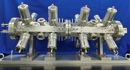
Fig.8 (Color online) RFQ prototype
whereQ0is the average of the quadrupole components.
The core of the problem is to solve the following equation:
where M is the response matrix, T is the movement of each tuner to be solved, and P is the error.Matrix M is not square.The singular-value decomposition method is typically used to solve such problems.This method was evaluated in a simulation; however, the results were unsatisfactory.Subsequently, the leas-squares method was used with iterations to solve this problem.This method offers some advantages,the most significant of which is its ability to impose a limit on the elements in T, thus implying that the solution can be confined to a specific range.Consequently, the obtained solution is the best within the range, i.e., it is not overly large or outside the range of the tuner movement.A flowchart illustrating the calculation process is shown in Fig.9.
5.2 Measurement setup
The measurements of the RFQ prototype are presented in Fig.10a.The magnetic field was measured using a vector network analyzer with two antennas.Details regarding the method by which the field was obtained are described below.Initially, the prototype RFQ was measured with all 16 tuners at the same depth; subsequently, the depth was varied until the frequency reached 714 MHz.The mode frequencies differed from those in the simulation (Fig.10b).The frequencies of the TE111modes were approximately 3.5 MeV lower than that of TE210; however, they were approximately 5 MHz higher in the simulation.
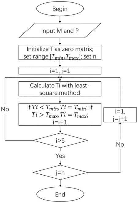
Fig.9 Flowchart for solving the matrix
The field distribution was measured under these conditions at the initial state.Prior to further comparison and calculation, the data were processed for normalization,reorganization, and trimming.Furthermore, the quadrupole and dipole components were calculated, as shown in Fig.10c.The peaks on the line were extremely high because the frequency was lower than that in the simulation when the depth of the tuners was the same; hence,the tuners were inserted deeper.The fields in quadrants a and c differed significantly, which resulted in a dipole component that was > 30% (exactly 31.7%) larger than the quadrupole component.The quadrupole component error was 4.4%.
The depth and movement of the tuner were determined by counting the number of nut rotations.Here, symbols“ − ” and “ + ” represent shallower and deeper positions,respectively.The distance that the tuner traversed per turn was ~ 0.9 mm.Prior to tuning, the response matrix was measured, with each tuner traversing two turns (− 2 turns).For the tuning calculation, six positions in the field were selected, as indicated by the quadrupole component curvature shown in Fig.10c.
5.3 Tuning progress
First, tuning was performed without the DSRs to evaluate the tunning method.To efficiently apply penetration to the tuners, the limit for all tuners was set as − 5 turns to+ 3 turns.The dipole components were not multiplied by the first three tunings.The quadrupole component error was 2.0% after three tunings; however, the dipole component errors were extremely high at approximately 15%.Subsequently, the dipole component errors were assigned different weights from the quadrupole component errors.When the calculation method was changed, errors with large variations were observed.The errors decreased as the number of tuning iterations increased.After the 10th tuning, the dipole and quadrupole component errors decreased gradually to 2.2%and 5.9%, respectively.
Additional tunings were performed because several tuners had reached their movement limits.Furthermore, the limit for the tuners was changed to − 6 turns to + 4 turns.As expected, once the calculation program was changed, the errors increased.The best results were obtained after the 20th tuning.The errors were 2.2% and 5.2% for the quadrupole and dipole components, respectively, which were slightly higher than those obtained after the 10th tuning.The error variation during the tuning is shown in Fig.11.
Subsequently, DSRs were applied to the prototype and the tuners were realigned to reduce the difference in their depth.Because the frequency of the higher-order dipole modes was 30 MHz higher than that of the TE210mode, the DSRs were shifted only considering the TE111modes.The DSRs were inserted until the TE111modes were at almost the same frequency and 8 MHz lower than that of the TE210mode.During the adjustment, the frequency of the TE210mode changed less than the temperature and humidity fluctuations.The frequency was 713 MHz, whereas the dipole and quadrupole component errors were 24.09% and 1.57%,respectively.During the tuning, the dipole component errors declined significantly and the quadrupole component errors fluctuated more than they decreased.After five tunings, the quadruple and dipole component errors decreased to 2.33%and 1.39%, respectively.
The errors are insignificant and similar to the expected values.However, the frequency was 712.878 MHz, which was lower than expected.The frequency of the prototype should be 713.618 MHz at a temperature of 25 °C and a humidity level of 50%.The frequency was adjusted to 713.581 MHz after all the tuners were shifted 2/3t deeper.Using these data, the sensitivity of the prototype can be calculated such that the frequency would change by 1.2 MHz if all the tuners shifted by 1 mm, which is slightly smaller than that in the simulation.After frequency tuning, the dipole and quadrupole component errors changed to 2.52% and 1.34%,respectively, as indicated in Fig.11.

Fig.10 (Color online) Measurement setup: a measurement setup for the RFQ; b initial mode spectra of RFQ prototype, where the frequency of D1 is lower than that in the simulation; c initial field of RFQ prototype
Five additional tunings are performed to confirm the stability of the proposed method.The errors varied slightly during the process and converged thereafter.Considering that the response matrix was measured when the field contained large errors and thus might not be suitable after several tunings, a new response matrix was measured.However, no significant improvement was observed in the field.The errors did not change significantly during the final two tunings, and reducing them was assumed to be difficult.The error variations are shown in Fig.11.
5.4 Matched results after tuning
The field of the RFQ prototype after frequency tuning, as indicated in Fig.11, is shown in Fig.12a and is compared with the initial field after applying the DSRs.The mode spectra of the RFQ prototype at the final condition are presented in Fig.12b.The tuning resulted in a low level of errors, and some issues remained that limited the further improvement of the results.First, calibration was insuffi-cient.Although the tuners were designed to be adjustable,they failed to shift precisely without calibration.In addition,the flanges of the tuners were adhered to the cavity rather than welded because they were made of aluminium and not completely stable.Therefore, small perturbations may occur when shifting the tuners because of their instability, and the movement calculated by the program cannot be precisely applied to the prototype.Furthermore, ensuring that all the tuners were at the same depth was difficult because of the matching errors of the cavity, which resulted in large dipole components.During the tuning, the tuners were shifted by counting the number of nuts with a precision of ~ 0.1 mm.However, we aimed at achieving a precision of ~ 0.01 mm with calibration.Imprecise movement of the tuners can result in significant tuning errors.

Fig.11 (Color online) Errors variations during tunings.Variations in errors of a quadrupole component and b dipole component

Fig.12 Tuning results of the prototype: a Comparison of field before and after tuning as indicated in Fig.11; b mode spectra of the prototype after tuning
6 Mechanical design and future plan for entire RFQ
Thus, the mechanical design of the compact RFQ was complete.The 2-m-long RFQ was classified into four modules.Some disadvantages discovered from the experiment based on the prototype, such as those pertaining to the tuners, have been addressed in the formal mechanical design.The tuners were not designed to be vacuum qualified but to be more precise.The calibration of the tuners is illustrated in Fig.13.As mentioned previously, the tuners demonstrated a precision of 0.01 mm.The compact RFQ is planned for fabrication in the near future.

Fig.13 (Color online) mechanical design of the formal RFQ
7 Conclusion
A 714-MHz RFQ was designed for compact proton injectors with high transmission efficiency.The beam dynamics design of the RFQ was completed with a preliminary design of the entire injector with an IH-DTL demonstrating excellent matching between the two components.Subsequently,an aluminium prototype was machined to examine the fabrication procedure, and invaluable manufacturing experience was obtained during the process.Additionally, a novel tuning algorithm was developed and validated for the prototype,and the results indicated small errors in the prototype.Based on this study, a formal mechanical design of a compact RFQ was completed, and its construction was planned.In the future, the compact RFQ will be developed into compact proton injectors for medical applications.Furthermore, it can facilitate the development of FLASH.
Author contributionsAll authors contributed to the study conception and design.Material preparation, data collection and analysis were performed by YXL and YSG The first draft of the manuscript was written by YXL and all authors commented on previous versions of the manuscript.All authors read and approved the final manuscript.
Data availabilityThe data that support the findings of this study are openly available in Science Data Bank at https:// cstr.cn/ 31253.11.scien cedb.j00186.00369 and https:// doi.org/https:// doi.org/ 10.57760/ scien cedb.j00186.00369.Declarations
Conflict of interestWen-Cheng Fang and Zhen-Tang Zhao are editorial board members for Nuclear Science and Techniques and was not involved in the editorial review, or the decision to publish this article.All authors declare that there are no competing interests.
 Nuclear Science and Techniques2024年1期
- Nuclear Science and Techniques的其它文章
- Infrared microspectroscopy beamline BL06B at SSRF
- Millisecond dynamics of colloidal suspension studied by X‑ray photon correlation spectroscopy at the Shanghai Synchrotron Radiation Facility
- Uncertainty and sensitivity analysis of in‑vessel phenomena under severe accident mitigation strategy based on ISAA‑SAUP program
- Generation and regulation of electromagnetic pulses generated by femtosecond lasers interacting with multitargets
- NνDEx‑100 conceptual design report
- A new liquid membrane diffusion model for characterizing the adsorption kinetics of europium by using a continuous measurement of adsorption platform