
NνDEx‑100 conceptual design report
2024-03-09 08:52:20XiGuangCaoYanLongChangKaiChenEmilioCiuffoliLiMinDuanDongLiangFangChaoSongGaoSurjaGhoruiPengChongHuQiangHuSiYuanHuangZeYuHuangLeiLangYuLanLiZhiJieLiTianYuLiangJunLiuChenGuiLuFaTaiMaiYuanMeiHaoQiuXiang
Nuclear Science and Techniques 2024年1期
Xi‑Guang Cao · Yan‑Long Chang · Kai Chen · Emilio Ciuffoli · Li‑Min Duan · Dong‑Liang Fang ·Chao‑Song Gao · Surja K.Ghorui · Peng‑Chong Hu · Qiang Hu · Si‑Yuan Huang · Ze‑Yu Huang · Lei Lang ·Yu‑Lan Li · Zhi‑Jie Li · Tian‑Yu Liang · Jun Liu · Chen‑Gui Lu · Fa‑Tai Mai · Yuan Mei · Hao Qiu ·Xiang‑Ming Sun · Xiao‑Xing Tang · Hu‑Lin Wang · Qian‑Ming Wang · Le Xiao · Mu‑Yun Xiao · Jian‑Yu Xin ·Nu Xu, · Peng Yang · Yi‑Chen Yang · Zhen Yang · Zong‑Yang Yu · Dong‑Liang Zhang · Jun‑Wei Zhang ·Cheng‑Xin Zhao · Dou Zhu · NνDEx‑00 collaboration
Abstract Observing nuclear neutrinoless double beta (0νββ ) decay would be a revolutionary result in particle physics.Observing such a decay would prove that the neutrinos are their own antiparticles, help to study the absolute mass of neutrinos, explore the origin of their mass, and may explain the matter-antimatter asymmetry in our universe by lepton number violation.We propose developing a time projection chamber (TPC) using high-pressure 82SeF6 gas and Topmetal silicon sensors for readout in the China Jinping Underground Laboratory (CJPL) to search for neutrinoless double beta decay of 82Se, called the N ν DEx experiment.Besides being located at CJPL with the world’s thickest rock shielding, N νDEx combines the advantages of the high Qββ (2.996 MeV) of 82 Se and the TPC’s ability to distinguish signal and background events using their different topological characteristics.This makes N νDEx unique, with great potential for low-background and high-sensitivity 0 νββ searches.N νDEx-100, a N νDEx experiment phase with 100 kg of SeF6 gas, is being built, with plans to complete installation at CJPL by 2025.This report introduces 0 νββ physics, the N νDEx concept and its advantages, and the schematic design of N νDEx-100, its subsystems, and background and sensitivity estimation.
Keywords Neutrinoless double beta decay · Time projection chamber · 82SeF6 · China Jinping Underground Laboratory
1 The physics
The standard model (SM) of particle physics is an important cornerstone of physics and the entire natural sciences that has successfully undergone experimental testing for more than half a century.The discovery of its last component, the Higgs particle, marked the perfect end of an era.In the SM,neutrinos have no mass.However, their oscillations, which have been observed nowadays by many independent experiments and are supported by irrefutable evidence, require the presence of a non-diagonal mass term in the flavor basis.This is the first experimental proof of physics beyond the SM in particle physics.Some properties of neutrinos remain unknown, such as whether they are Dirac or Majorana fermions, their absolute mass, and their mass hierarchy.
The charged fermions in the SM are all Dirac particles,which gain mass through Yukawa coupling with the Higgs boson.Because neutrinos are electrically neutral, they are the only candidates in the SM to be Majorana fermions,i.e.,they could be their own antiparticles.If this is the case, we can also explain why their masses are significantly lower than those of other charged leptons in the SM by introducing a seesaw mechanism [1].Neutrinoless double beta decay experiments are the ideal way to determine if this is the case;if such a process is observed, it would be irrefutable proof that neutrinos are Majorana particles, opening the door to new physics.The measured decay rate can quantitatively constrain the absolute mass and mass ordering of neutrinos.Additionally, neutrinoless double beta decay violates lepton number and CP parity conservations, which can generate a net lepton number in the early universe evolution, thus explaining the matter-antimatter asymmetry in the universe.
2 NvDEx Concept and its advantages
The rate of neutrinoless double beta (0νββ) decay occurrence (if it occurs) is extremely low, making experimental observations difficult.These experiments have been developed for decades, with intense competition among the various experimental approaches.Existing large-scale experiments include GERDA [2], MAJORANA [3], CUORE [4],CUPID [5], KamLAND-Zen [6], and EXO [7].In China,experiments including CDEX [8], PandaX [9], CUPIDChina [10], and JUNO [11] have searched for or are being developed to search for 0νββdecay.Currently, the highest experimental half-life sensitivity reaches 1025–1026years,yet no such decay has been observed.Next-generation 0νββdecay experiments are approaching the sensitivity needed for the inverted hierarchy of neutrino masses, on the order of 1027years for most 0νββdecay isotopes.For the normal hierarchy of neutrino masses, which is slightly favored by oscillation experiment results, the required experimental half-life sensitivity is two orders of magnitude higher, on the order of about 1029years.
Reducing the experimental background is key to improving the sensitivity of neutrinoless double beta decay experiments.With zero background, the experiment’s sensitivity is proportional to the exposure (mass of decay isotope ×experiment time).However, with a high background, the experimental sensitivity increases with the square root of exposure [12].Thus, to increase experimental sensitivity by another 1-3 orders of magnitude, innovative techniques must be applied to significantly reduce the experimental background.
The concept of a “No neutrino Double-beta-decay Experiment (NνDEx),” searching for the neutrinoless double beta decay of82Se using a high-pressure gas time projection chamber (TPC) with82SeF6as the working medium and read out by Topmetal sensor chips, was proposed by Nygren et al.[13].This scheme combines the highQββof82Se with the ability of TPC to distinguish between the signal and background using event topology, which can significantly reduce the experimental background.TheQββof82Se is as high as 2.996 MeV, which is higher than most natural radioactive backgrounds and that of the decay isotopes currently used in many mainstream experiments.For example, the natural radioactiveγbackground near theQββof82Se is more than two orders of magnitude lower than that around theQββof136Xe (2.458 MeV).Meanwhile, in gaseous TPC, the double beta decay can be reconstructed as two electron tracks, each with a distinct Bragg peak at the end.This feature can be used to distinguish the signal from the background.
However, this experimental concept faces a major technical challenge: SeF6is an electronegative gas, in which the electrons generated by ionization quickly combine with gas molecules to form negative ions, and electron avalanche amplification cannot happen.Thus, the weak signals cannot be read out with traditional technologies.To solve this problem, we designed the Topmetal-S sensor [14, 15], a kind of silicon sensor chip with a layer of metal on top, dedicated to 0νββdecay experiments, making TPC without physical amplification possible.It adopts an industrial semiconductor CMOS process, and the top layer has a metal sheet for charge collection.In principle, its noise level can be as low as about 30 e−; thus, the primary ionized charge can be directly read out without physical amplification, providing a unique opportunity to search for 0νββdecay using the82SeF6gas TPC.
The construction of the China Jinping Underground Laboratory (CJPL) provides a unique opportunity for developing 0νββdecay experiments.CJPL has the thickest natural rock shield in the world, and the second phase of CJPL is being constructed with a world-class experimental space and a low-background environment.NνDEx will be developed at CJPL, taking full advantage of its low background level and large space.
3 NvDEx‑100 schematic design
3.1 NvDEx‑100 overall design
This study develops a NνDEx-100 experiment with 100 kg of natural SeF6gas.The preliminary design is shown in Fig.1.The main body of the experiment is in a pressure chamber, with feedthrough flanges for gas, low voltage, optical fibers, and high voltage.An inner copper shielding inside the pressure chamber shields most of the external radiation.The core detector of the experiment–TPC–is installed in the barrel part of the chamber, comprising an insulating layer, a high-voltage plane, a field cage, and a readout plane.The readout plane consists of the focusing layer and the readout electronics layer on which the Topmetal-S sensor chips are mounted.In addition to the main body of the experiment, there are lead and high-density polyethylene(HDPE) external shieldings surrounding the pressure chamber, as well as auxiliary facilities such as the gas system,which are not shown in Fig.1.

Fig.1 (Color online) Schematic design of the main part of the N ν DEx-100 experiment
During the experiment,82Se (with a natural abundance of 8.7%) in SeF6gas undergoes double beta decay, releasing two electrons.The total energy of the two electrons is 2.996 MeV for the neutrinoless double beta decay.These two electrons lose energy in the gas, ionize the gas, and form curved tracks due to scattering.At the ends of the two tracks, two Bragg peaks with the largest energy loss are formed.Due to the electronegativity of SeF6, the electrons generated by ionization quickly form negative ions with surrounding SeF6molecules.Finally, various SeF±Nions are formed in certain fractions, including SeF+0−5and SeF−5,6, which drift to the two ends of the TPC in the electric field.After the SeF−5,6ions reach the readout plane, their signals are read out.The drift velocities of SeF−5and SeF−6ions are different, as are their arrival times.This time difference can be used to obtain the drift distance.The readout plane comprises the focusing and readout electronics layers; the focusing layer generates a certain electric field structure with small holes that allow the passage and collection of drift charges with 100% efficiency at the 1 mm2-sized readout electrodes on the surface of the Topmetal-S chips.The Topmetal-S chips, located on the surface of the readout electronics layer, measure the charge and time of the signal and generate digital data, which are collected by the electronic readout boards and transmitted to the data acquisition computer through the optical fibers.
3.2 Pressure chamber and inner copper shielding
NνDEx-100 uses the SeF6gas at a pressure of 1.0 MPa.This pressure is chosen to obtain more SeF6gas mass within a certain volume while avoiding liquefaction [13].The pressure chamber design is shown in Fig.2.The chamber comprises a barrel and two end caps, connected with two DN1200 Tongue–Grove (T–G) flanges.There are seven smaller T-G flanges on each end cap: one DN50 flange for gas, one DN80 flange for high voltage, four DN125 flanges for low-voltage and optic fibers, and one DN150 flange for vacuum.The inner diameter and length of the barrel are 1200 mm and 1760 mm, respectively.The chamber is made of 10-mm-thick, low-background, stainless steel.Figure 3 shows the cross-sectional view of the chamber.The weight of the chamber is around 2211 kg without considering the bolts.The barrel part of the pressure chamber sits on two saddles, while the two end caps are supported with carts,which can move away along the rails when opening the chamber.
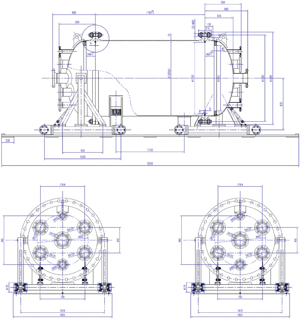
Fig.2 Design of the pressure chamber

Fig.3 Cross-sectional view of the pressure chamber
A 12-cm-thick oxygen-free copper shielding with low radioactive isotope contamination is placed inside the pressure chamber to suppress the background radiation from the pressure chamber and outside, as shown in Fig.1.Figure 4 shows a cross-sectional view of the inner copper shielding design, comprising a barrel part and two disks mounted in the end cups of the pressure chamber.The outer and inner diameters of the barrel part are 1190 mm and 950 mm, respectively.The barrel part and the disks weigh about 6108 kg and 1476 kg, respectively.The disks have some holes enabling the passage of gas, optic fibers,low-voltage cables, and the high-voltage feedthrough.The holes, except the ones for high voltage, are tilted to avoid outside radiation reaching the sensitive volume of the TPC via a straight path.
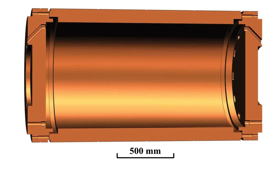
Fig.4 (Color online) Cross-sectional view of the designed inner copper shielding
The Topmetal sensors and electronics on the readout plane will generate heat when taking data, which will induce convection in the SeF6gas in the sensitive volume, with a maximum velocity larger than 10 cm/s assuming heat power of 700 W on the readout plane.This could be a problem for NνDEx TPC because the ions drift very slowly, with a velocity above 20 cm/s, which is significantly lower than the drift velocity of electrons (on the order of several cm/μs in most other TPCs), and the convection could cause serious distortion of the reconstructed event topology.Thus, cooling the readout plane and minimizing the temperature nonuniformity inside the TPC is necessary.For this purpose,a copper heat conductor will be placed between the inner copper shielding disk and the end cap of the pressure vessel.As shown in Fig.1, the heat conductor is composed of a base (in yellow) and a tube (in purple) fixed to the inner copper shielding disk and to the pressure chamber end cap,respectively.Figure 5 shows the cross-sectional view of the copper heat conductor with dimensions.The base and the tube can slide horizontally relative to each other.This design ensures good contact between all neighboring parts along the heat conduction path, even when the pressure chamber expands due to the gas pressure, so that the total heat resistance is acceptable.The weight of the copper heat conductor is around 489 kg.A liquid cooling plate will be mounted on the outer surface of the end cup of the pressure chamber.The temperature difference in the TPC and convection in the gas will be minimized by adjusting the temperature of the cooling plate.

Fig.5 (Color online) Cross-sectional view of the cooling base and tube
The SeF6and82SeF6gases are very expensive.Two plastic fillers will be placed in the end caps of the pressure chamber to reduce the amount of the gas to be used, occupying the gap outside the inner copper shielding disks, as shown in Fig.1.Since SeF6is toxic, any material that absorbs the gas and gradually releases it when the pressure chamber is open during the maintenance of the experiment could endanger people and the environment.Considering this, the fillers, as well as the insulator layer and the TPC field cage supporting cylinder to be described in the next subsection, will be made of polyoxymethylene (POM), which absorbs the minimum amount of gas among plastic materials with acceptable mechanical strength.The design of the fillers is shown in Fig.6.There are also some holes in the fillers for gas, optic fibers, low-voltage cables, and the high-voltage feedthrough to go through.
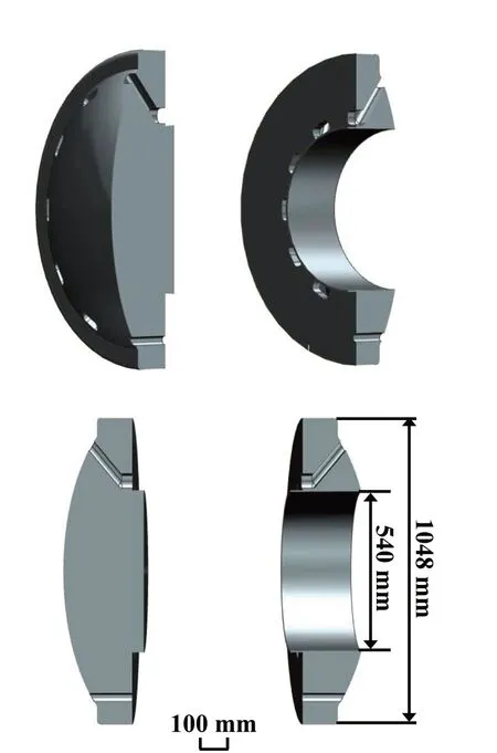
Fig.6 Cross-sectional view of the POM fillers
The pressure chamber and the inner copper shielding have been manufactured for an above-ground prototype experiment.The copper heat conductor and the fillers are being manufactured.The above-ground prototype will be assembled in the near future.Then, tests of the gas tightness of the pressure chamber, heat conduction, and temperature control of the readout plane will be conducted.
3.3 Field cage
The electronegativity of the SeF6gas used in NνDEx-100 is very high.This means the negatively charged particles drifting toward the readout plane will not be electrons since they are quickly captured, but negative ions instead.The readout plane will employ innovative Topmetal-S sensors to read out the drifted charge without physical amplification like an electron avalanche.Details about Topmetal-S sensors and the readout plane will be introduced in Sect.3.4.
Most of the drift negative ions will be SeF−6and SeF−5;however many more complex molecules may be formed.The drifting negative ions may form clusters like SeF−6(SeF6)nand SeF−5(SeF6)n(n=1,2,3,...) with a low drift field.These clusters will smear the drift velocity of the negative ions, resulting in increased noise.Similar to SF6, the cluster formation in SeF6can be suppressed with high drift fields.Consequently, the drift field of NνDEx-100 will be as high as 400 V/cm, corresponding to a drift velocity of negative ions above 20 cm/s.

Fig.7 (Color online) Cross-sectional view of the design of a prototype field cage
A cross-sectional view of a prototype field cage (FC)design is shown in Fig.7.The FC is isolated from the inner copper shielding by a 20-mm-thick POM cylinder.The FC will be made of flexible printed circuit (FPC) sheets sized 315 mm×423 mm.Each FPC has 5-mm-wide copper strips with a pitch of 6 mm on both sides.Three snap-offholes at both ends and the center of each copper strip will be used to align and fix the FPC sheets onto a 10-mm-thick POM supporting cylinder with screws.Two copper rings will be mounted at the two ends of the POM supporting cylinder.The copper strips and copper rings will be connected using low radioactive background resistors.The cathode of the TPC will be a low radioactive background copper plane mounted on the inner copper shielding disk, isolated with a POM layer of thickness 25 mm.Eight pogo pins will be used to ensure a good connection between the cathode plane and the copper ring on the end of the cylinder part of the FC once the pressure chamber is closed.
A high-voltage feedthrough will be connected to the cathode by spring pins.It is constructed using a compression seal approach, as shown in Fig.8.A metal rod is pressed into a Polytetrafluoroethylene (PTEF) seal ring by clamping nuts on a DN80 flange.The feedthrough has been tested with a high voltage of 100 kV and for leak tightness in nitrogen at 1.0 MPa.
3.4 Topmetal‑S sensor and readout plane
Around 10k CMOS sensors, named Topmetal-S, arranged in a hexagonal pattern as shown in Fig.9, will be directly placed at the site of charge measurement to collect ionization charges without avalanche multiplication.A perforated focusing electrode is placed above the readout plane with round holes aligned with the charge collection electrodes on the Topmetal-S sensors concentrically.The focusing structure ensures all charges eventually land on the charge collection electrode for maximum charge collection efficiency.

Fig.8 (Color online) Image of the high-voltage feedthrough

Fig.9 (Color online) Topmetal-S sensors tiled in a hexagonal pattern to form a charge readout plane without gas gain
Each Topmetal-S sensor is integrated with a charge collection electrode, a front-end amplifier, and data processing circuits.The charge collection electrode is an exposed hexagonal top-most metal with a diameter of about 1 mm.The charge signal collected on the Topmetal electrode is directly DC coupled to the charge sensitive pre-amplifier (CSA).The structure of the CSA in the prototype Topmetal-S sensor is a folded cascade amplifier with a feedback capacitor and a feedback transistor.The decay time of the CSA can be adjusted by changing the gate voltage of the feedback transistor.
Due to the stringent noise requirement, the analog signal of the CSA output must be digitized immediately.Thus, an in-chip analog-to-digital converter (ADC) is designed to minimize the analog signal transfer.The ADC should have a noise floor well below the noise of the CSA of about 1 mV and a large enough dynamic range to cover the possible input charge range up to about 40 ke−.A sigma-delta (SD) ADC is used in the Topmetal-S sensor.It comprises an SD modulator (analog part) with coarse quantizers and a decimation filter (digital part) together to produce a data-stream output.By sampling the input signal at a frequency significantly higher than the signal bandwidth (oversampling), most of the noise shifts beyond the band of interest.A decimation filter further attenuates the out-of-band noise to achieve an improved signal-to-noise ratio.A photograph of the Topmetal-S sensor chip is shown in Fig.10.
Since the sensors are densely packed on the plane, the number of available paths for the routing signal out of the plane is limited.Beyond a certain plane size or total number of sensors, routing every signal from all sensors out becomes impractical.Digitized data must be communicated through an inter-sensor network.Therefore, the circuitry that handles data processing and communication must be integrated into the sensor.A distributed, self-organizing, and fault-tolerant readout network is proposed with the Topmetal-S sensor.The proposed scheme forms a sensor network by establishing a local connection between the adjacent sensors.Each sensor integrates a router as a network node; hence, each sensor not only generates and transmits its data but also forwards the data from its adjacent nodes.Finally, the data are received by a data acquisition system, which is directly connected to the network edge and used to transmit the data between the sensor network and the computer.
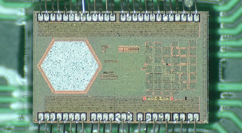
Fig.10 (Color online) Photograph of the Topmetal-S sensor chip
3.5 Data acquisition
Based on the two-dimensional distributed network formed by the digital part of the Topmetal-S sensors, the digitized waveform of each CSA output will be transmitted to the edge of the plane as the streaming readout.The speed of the data chain could go up to 45 Mbps.As shown in Fig.11,the full plane is split into modules with different sizes to cover the end cap as much as possible.All the streaming data chains end in the modules on the right side, where the data are further encoded and aggregated into high-speed links with a speed of a few Gbps, by the commercial transceiver chips.Depending the on orientation of the sensors and how the sensors on the edge columns are connected to the transceiver, there will be 20~ 50 bidirectional high-speed links in total to connect the readout plane and the DAQ system in the back-end.In the other direction, the control data streams from the DAQ system are transmitted toward the left side of the readout plane.
The flexible Printed Circuit Board (PCB) modules will be fabricated with radiopure material.CMOS chips, such as the Topmetal-S sensors, are known to be low in radioactive contamination.Other components, including the capacitors, resistors, transceivers, and some power chips, will be selected carefully.The radioactivity measurements will be done in the CJPL.Besides the material and components,any tools or materials used during the assembly procedures should also be clean enough.
A PCIe-based DAQ system will be built in the backend to communicate with the front-end electronics on the readout plane via high-speed fiber optic links.A similar PCIe form factor has been adopted by dozens of large-scaleexperiments, such as the ATLAS experiment at the LHC and the sPHENIX experiment at the RHIC [16, 17].The streaming data from all sensors are received and decoded by FPGAs on the PCIe cards.The data processing, event building, and filtering can be flexibly placed in the chain from the FPGA firmware to the software.The raw data and kinds of intermediate-stage data will be streamed from the DAQ server to a high-speed switch.Any client connected to the network can remotely subscribe to the data and implement further data analysis.

Fig.11 (Color online) Architecture of the DAQ system
3.6 External shielding
An external lead shielding with a thickness of 20 cm will be built outside the pressure chamber to protect the NνDEx detector from environmental radiation.The preliminary design of the external lead shielding is shown in Fig.12.It comprises two mobile halves and a fixed base on which the pressure chamber sits.The mobile halves, including the side walls and the top, are installed on a mobile base connected to a transmission system so that they can be adjusted to enable opening and operations on the pressure chamber.The fixed base is installed on a vibration isolation system to minimize the influence of vibration on the experimental measurements.The vacuum and gas pipes, high- and lowvoltage cables, and the optical fibers will pass the external lead shielding through several holes at the joints of the two mobile halves.Two shielding doors will be installed to prevent radiation from going through these holes directly.The lead bricks and the steel structure inside the lead layer will be selected and tested for radioactive contamination.
Lead is very effective for stopping externalγradiation;however, it is not a good shielding material for neutrons.High-density polyethylene (HDPE) blocks will be placed as much as possible between the pressure chamber and external lead shielding to slow down and absorb neutrons.The lead shielding exterior will also be covered with a 30-cm-thick layer of HDPE.The HDPE material will also be tested for radioactivity.
3.7 Gas system
The working medium of NνDEx is highly toxic SeF6gas.When there is moisture in it, SeF6can easily decompose and produce corrosive HF, which may damage detector components and/or cause toxic gas leakage.The gas system of NνDEx can fill the pressure chamber with SeF6to the working pressure of 1 MPa, discharge the gas from the pressure chamber, and safely store it during experimental maintenance.During the lifetime of the experiment, the pressure vessel will be pressurized, depressurized, and vacuumized many times, and the pressure vessel and part of the gas system will operate at a pressure of 1 MPa for years during data collection.Thus, gas tightness and reliability are critical for the NνDEx gas system.
With these considerations, the schematic of the NνDEx gas system is designed as shown in Fig.13.
The pressure chamber is connected to a turbomolecular vacuum pump and a dry vacuum pump, which can vacuumize the chamber and the gas system before filling SeF6gas.This can minimize contamination of the SeF6gas by air, moisture, and radon to avoid corrosion and radiation background from the gas.
Every time before filling the toxic SeF6gas to the chamber, SF6, which has similar properties as SeF6but is nontoxic, is filled into the system with a pressure of 1 MPato test the gas tightness of the pressure chamber and gas system.After the test, SF6is compressed into a SF6storage tank for future use.

Fig.12 (Color online) Design of the external shielding

Fig.13 Schematic of the N νDEx gas system
In emergencies such as gas leakage, fire, an earthquake,and a power outage, SeF6gas in the system will be released into an emergency pressure relief tank within 10 seconds so that the pressure in the system is below atmospheric pressure to ensure personnel and environmental safety.
Before experimental maintenance, SeF6gas is discharged from the pressure chamber and condensed by the low temperature in a precooler and two condensers.After the SeF6saturated vapor pressure is reached, a dry vacuum pump pumps the gas from the pressure chamber to the condensers.Then, any trace amount of SeF6left in the system is flushed by nitrogen gas into a potassium iodide(KI) reactor to be absorbed.The SeF6is safely stored in the condensers at low a temperature as solid and vapor below atmospheric pressure, which can be refilled in the pressure chamber in future.
All the components for the gas system have been purchased and are waiting to be assembled once the experimental pressure chamber manufacture is complete.Before moving to CJPL, the system will be commissioned and tested in the above-ground lab with SF6gas.
3.8 Airtight clean room
The entire experimental setup is placed in an airtight clean room to ensure the whole experimental process is safe.Enough potassium iodide (KI) reagent is placed in the airtight clean room as a second line of defense for environmental safety.
The control room is located outside the airtight clean room.Under normal working conditions, the airtight clean room is in an airtight state, and the entire experimental setup,including the gas system, can be controlled remotely.In case of a gas leakage, the gas system releases the SeF6gas into the pressure relief tank, and the KI reagent placed in the airtight clean room reacts with the leaked SeF6and absorbs it.The airtight clean room is divided into three areas that are airtightly isolated from each other.The main experimental setup and most gas systems are located in one area.Two SeF6condensers that serve as backups for each other are placed in the other two areas.When people need to operate the experiment in the main area of the experimental setup,all SeF6gas should be condensed in one of the condensers first to eliminate SeF6gas in the main area.Further, the pressure inside the condenser is the vapor pressure of SeF6,which is far below atmospheric pressure, so the leakage of a large amount of gas is impossible.In rare cases where people need to conduct on-site operations on a condenser, SeF6is first condensed in the other condenser.Therefore, people are always in an airtight clean room without SeF6gas.
The airtight clean room needs to reach a clean level of 100k to control the background radioactivity by preventing the surface of the detector from being contaminated.The temperature in the airtight clean room needs to be controlled at 22 ± 2◦C to minimize the gas convection in the TPC.Concurrently, the humidity must be 30 ± 10% to avoid moisture condensation at cold spots in the experimental setup, such as the cooling plate on the pressure chamber.

Table 1 Activity assumed for each material
4 Background and sensitivity estimation
4.1 Natural radioactive γ background
Radioactive isotopes are always present in the walls of the hall and in the rock surrounding them, as well as in the materials of the experimental setup.The decay of these isotopes produces a large amount ofα,β, andγparticles.However,the first two will mostly be stopped without causing a detectable background unless they are generated in or near the sensitive volume.So, we mainly focus on the latter.γparticles penetrating into the sensitive volume may interact with the gas and generate free electrons visible to the detector, making them a major background source for NνDEx.
A 20-cm-thick external lead shielding and a 12-cm-thick inner copper shielding outside and in the pressure chamber shield the externalγparticles.The thicknesses of the shielding layers are optimized using Geant4 simulations [18–20].Owing to the presence of radioactive contamination in the shielding materials, theγflux in the sensitive volume does not always decrease as the shielding thickness increases.
Assuming Topmetal-S sensors can achieve 30 e−noise level, on average, 25 sensors are fired per 0νββevent, and the ionization energy and Fano factor of SeF6are equal to that of SF6(32 eV, 0.19), then the FWHM energy resolution calculated is 0.51%.Considering deviations from the above assumptions and imperfections of the experiment, to be conservative, we assume 1% FWHM energy resolution and use this energy range (2.98–3.01 MeV) as the region of interest(ROI) in the following background estimations.
Most of the ROIγbackground comes from the decay of214Bi from the238U decay chain.The probability of having aγwith energy larger than 2.9 MeV from a214Bi decay is 6.8×10⁻⁴[21], which is quite rare.This is the advantage of82Se’s highQββfor NνDEx.208Tl from the232Th decay chain contributes about one order of magnitude less ROI background than214Bi, with only around 8.5×10⁻⁵[21] of the producedγhaving energy around and above the ROI.Thus,we only focus on the238U decay chain in ourγbackground simulation and estimation.

Table 2 γ background from different sources without suppression using event topology
The238U radiation activities of materials considered in our simulations are listed in Table 1.The238U activity of the concrete in the experimental hall walls is from a measurement at CJPL [22].The contribution of the rocks is negligible since the contamination rate of the rocks is significantly lower than that of the concrete.For other materials in the experimental setup, we used the measurements from the NEXT experiment [23].These numbers will be updated using measurements of materials for NνDEx in future.The activity of the POM material used for the TPC field cage is assumed to be identical to that of HDPE in NEXT.Many other parts or materials, for example, the SeF6gas, Topmetal-S sensors, flexible PCBs used in the field cage and readout plane, bolts on the pressure chamber, and various steel supporting structures outside the pressure chamber, are not considered in the current simulation because of their relatively smaller sizes, lower background contributions,complications in building the geometry model, and/or lack of knowledge on their radioactive activities.For these reasons, the current background simulation only serves as a rough estimation and guides hardware developments.
The natural radioactiveγbackground simulation results are reported in Table 2.The largest contribution comes from the POM of the field cage because it is close to the sensitive gas volume.The total ROIγbackground level is about 0.4 evts/yr.Note that, like most other types of backgrounds described in the following subsections, this background can be further suppressed by one order of magnitude using a neural network considering event topology information [13],to the order of only 0.04 evts/yr in the ROI.
4.2 Neutron background
Radioactive decay can also emit neutrons.These events are quite rare; however, since it is significantly more difficult to stop neutrons thanγ, the former can arrive more easily at the sensitive volume.Neutrons do not create ionization signals directly, but they can activate nuclei inside the detector, creatingγvia (n,γ) and (n,n’γ) reactions.
Neutrons can also create unstable isotopes, which decay and emitαorβparticles.However, unlikeγparticles, theseαandβparticles can generate background only if they are created in or near the fiducial volume; otherwise, they would be stopped almost immediately.
Among the isotopes that can be created in the fiducial volume by the neutrons, four contribute to the background:20F,16N,19O, and83Se.They can be produced through the following reactions.
In principle, other unstable isotopes can also be created, but theirQ-values are significantly lower than that of the82Se 0νββsignal; therefore, we do not need to consider them.
We studied the neutron-induced background rate using the fast neutron spectrum measured at CJPL and reported in [28] using Geant4 and FLUKA [24–27] packages.The results can be found in [29].
Neutron-inducedγis the main source of the neutron background, while theαandβdecays of unstable isotopes created by neutrons are strongly subdominant.Without any HDPE shielding, the ROI background rate of the former will be 1492 evts/yr, while that of the latter will be 39 evts/yr.
Thus, HDPE shielding is added to stop neutrons.Unlike high-Zmaterials such as copper and lead, HDPE contains many hydrogen nuclei, which can slow down and absorb neutrons very effectively.HDPE blocks are placed between the external lead shielding and pressure vessel, and a 30-cmthick HDPE layer is placed outside the Pb shielding.Thus, it is possible to reduce the neutron-induced background to 0.03 evts/yr, strongly subdominant with respect to theγbackground directly from natural radioactivity.
4.3 Cosmogenic background
When materials used in the experiment are exposed to cosmic rays during production and transportation on the ground,they are activated, creating relatively long-lived isotopes.The half-lives of these isotopes, although much shorter than those of238U and232Th described in Sect.4.1, are long enough (for example, months to years) to make them an important background source, even after the materials are placed underground.
The spallation process by high-energy cosmic nucleons is a dominant process in the cosmogenic production of radionuclides.However, other reactions such as capture can also be important in some cases.Spallation reactions can produce many radionuclides, depending on the atomic number of the target material.On the Earth’s surface, isotope production is dominated by neutrons because protons are absorbed by the atmosphere.
Cosmogenic activation can be minimized by reducing surface exposure, for example, by shielding against cosmic rays, avoiding flights and storing on the ground, or even producing materials underground.Purification techniques can also eliminate many of the induced isotopes.However,these preventive measures make the experiment preparation more complex.Consequently, it is advisable to assess the relevance of the material exposure to cosmic rays for the experiments and its effect on sensitivity.To quantify the induced activity,A, of an isotope with decay constantλ, the production rateRof the isotope in the considered target and the exposure history must be well known.Specifically,Acan be computed as:
wheretexpis the time of exposure to cosmic rays andtcoolis the cooling time (time spent underground once shielded from cosmic rays).
Some direct measurements of production rates have been conducted for a few materials exposed in well-controlled conditions.However, in many cases, production rates must be evaluated from the flux (per unit energy) of cosmic rays,φ, and the isotope production cross section,σ, both depending on the particle energyE:
whereNtdenotes the number of target nuclei.We used the ACTIVIA code [30] to calculate the cosmogenic activation of the various materials used in NνDEx.The cosmogenic activation rate of various radioisotopes in SeF6gas, copper,lead, and steel and activities after exposure and cooling for certain durations are shown in Tables 3, 4, 5, and 6.Only isotopes with relatively long half-lives and highQ-values are listed because other isotopes do not create a background in the 0νββdecay ROI after being placed underground to cool for some time.

Table 3 Cosmogenic activation rate of various radioisotopesin enriched 82 Se and activities after exposure at sea level and cooling for certain durations

Table 4 Cosmogenic activation rate of various radioisotopes in copper and activities after exposure at sea level andcooling for certain durations
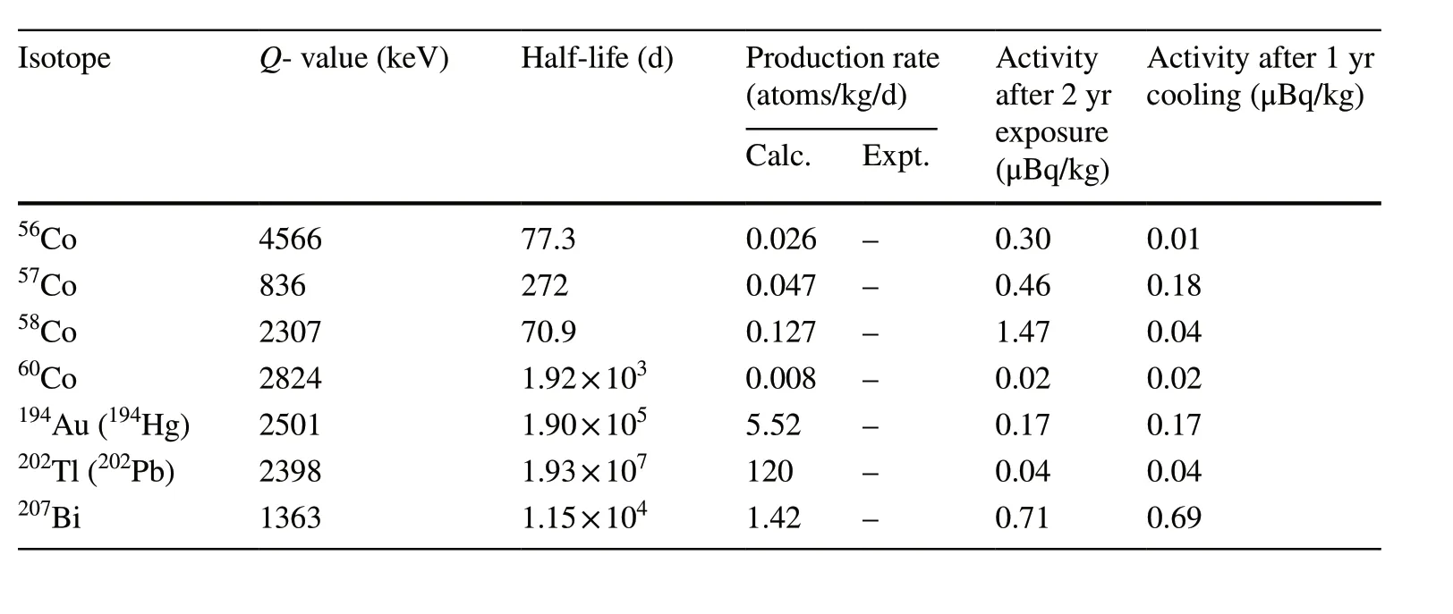
Table 5 Cosmogenic activation rate of various radioisotopes in lead and activities after exposure at sea level and cooling for certain durations.For short-lived isotopes with very long-lived parents (given in parentheses), we have considered the half-life of parent isotopes

Table 6 Cosmogenic activation rate of various radioisotopes in steel and activities after exposure at sea level andcooling for certain durations
From Table 3, we can see that56Co is the most important cosmogenic background isotope from82Se.It has aQ-value of 4566 keV, which is above the82SeQ-value,and a half-life of 77.3 days, long enough to have considerable activity of 0.02μBq/kg after two years of exposure at sea level and one year of cooling time.Cobalt fluorides are solid rather than gas at room temperature, and so far,we do not know whether or how much of the generated single-molecular56Co fluorides will remain in the gas after SeF6production, storage, and transportation.Assuming conservatively that all the56Co stays in the gas and reaches the sensitive volume of the experiment, for 100 kg of82SeF6with56Co activity of 0.02μBq/kg, approximately 26 decays will occur per year.Thus, energy deposition in the ROI will be minimal.
Cosmogenic isotopes from19F, with mass numbers no larger than 19, do not have relatively largeQ-values and long lifetimes simultaneously and thus will not constitute important cosmogenic background contributions.
The most important cosmogenic background isotope in copper is also56Co, as shown in Table 4.Considering that the inner copper shielding will be assembled and tested with the pressure chamber at the Institute of Modern Physics in Lanzhou, with an altitude of about 1500 m, the exposed cosmic neutron flux is about 3.2 times higher than at sea level.The56Co activity will be about 323μBq/kg after 2 years of exposure.Using the simulation framework described in Sect.4.1, we find that the ROI background in the sensitive volume from56Co emittedγ’s is as high as about 3700 evts/yr, which is much higher than the natural radiationγbackground.After three years of cooling, the ROI background will drop to a subdominant level of 0.19 evts/yr.So, it is important to place the inner copper shielding underground for cooling as early as possible.
The other isotopes in Table 4 haveQ-values lower than those of82Se.Therefore, they do not contribute to the ROI background alone.However, because the drift velocity of ions in NνDEx TPC is slow, there is a chance that ionization due to theγ’s from these isotopes adds up with other background sources, forming the so-called pile-up event backgrounds and reaching the82SeQ-value.This is described in Sect.4.5, taking60Co, which has a relatively long half-life and highQ-value, as an example of cosmogenic background isotopes.
As shown in Tables 5 and 6, the production rates of cosmogenic backgrounds in lead and steel are either lower than or comparable to those in copper.Considering that the inner copper shielding shields them from the sensitive volume ,their background contribution should be less important than the cosmogenic backgrounds in copper.
4.4 Other backgrounds
We also considered the following background categories for NνDEx, which are much lower than the natural radioactiveγ, neutron, and cosmogenic backgrounds and thus can be neglected:
• Natural radioactiveαandβbackground:αandβfrom natural radioactive isotopes have much shorter path lengths thanγand neutrons.So, they can influence the experiment measurement only if the radioactive isotopes are in the gas or on the surface of the sensitive volume.For the SeF6gas, since both the Se and F2gas materials are obtainable with high purity (99.999% for Se and 99.99% for F2), the radioactive isotope contamination should be low.This needs to be further studied and confirmed using ICP-MS measurements of the Se material or future analysis of the data from NνDEx.Fluorides of U and Th are solids at room temperature.So far, we do not know whether or how much of the U and Th will stay in the gas and enter the sensitive volume after production, storage, and filling of SeF6.Radioactive isotope contamination on the surface of the sensitive volume can be limited by carefully cleaning the components in the pressure chamber and gas system, especially directly on the surface of the sensitive volume, i.e., the inner surface of the field cage, the high-voltage plate, and the focusing plane.When analyzing the data,αandβfrom radioactive contamination on the surface of the sensitive volume can also be reduced by cutting the volume within a certain distance to the surface since the path length is within a few cm in the gas at 1 MPa.
• Radon background: Radon, as a radioactive gas that can be emitted from radioactive isotopes in the underground environment and materials in the experiment setup, may become a background source if it gets into the sensitive volume of the experiment.Fresh air will be flushed through the clean room where the NνDEx experiment is located to limit the level of radon contamination during the assembly, operation, and maintenance of the experiment.Additionally, during the experiment,the pressure chamber is airtight with a gas pressure of 1 MPa inside.Thus, the amount of radon penetrating the chamber should be minimal.Radon can also be emitted from the materials inside the pressure chamber.Both222Rn (half-life of 3.8 d) from the238U chain and220Rn(half-life of 55 s) from the232Th chain undergo alpha decay into polonium.A portion of the products in the following decay chain may be negative or positive ions,which drift toward the anode or cathode in the electric field of the TPC.Theαandβfrom the decay of radon and its decay products (if they are not ions and drift to the anode or cathode) are further suppressed by the event topology characteristics in the TPC.This is becauseαforms thicker and straighter tracks thanβ, and a singleβevent has one Bragg peak instead of two.214Bi and210Tl in the222Rn decay chain haveβdecay endpoint energy above the ROI and thus could contribute to the ROI background.However,214Biβdecay is immediately followed by a214Poαdecay with a half-life of 164μs andαenergy above 6 MeV.Thus, the sequentialβandαdecays are reconstructed as one event, whose total energy will be far above the82SeQββ.The210Tl, on the other hand, will only be generated from the214Biαdecay with a small branching fraction of 0.02%.So the ROI backgrounds from the214Bi and210Tlβdecays are limited.Otherαandβenergies in the222Rn and220Rn decay chains are mostly away from the82SeQββ, further limiting the chance to create any background in the ROI.γfrom the decay of radon and its decay products have a small chance of interacting with the gas, making a much smaller background contribution in ROI than the natural radioactiveγdirectly from the materials and environment mentioned in Sect.4.1.
• Cosmic muon background: As the deepest underground lab in the world, CJPL has a cosmic muon flux as low as 3.53±0.22(stat.)±0.07(sys.)×10−10cm−2s−1[32].NνDEx-100, as a meter-scale experiment at CJPL, only observes a level of 0.3 cosmic muons per day.These muon background events show straight tracks through the TPC, can easily be distinguished from 0νββsignal events, and thus can be neglected.A very small fraction of muons interact with the gas, creating some radioactive isotopes.The chance of this kind of background falling into the energy ROI is also negligible, considering the low muon flux at CJPL.
• Neutrino scattering background: Neutrinos from various sources can easily penetrate into the sensitive volume of the detector, but the chance of a neutrino interacting with the gas is very low.The most important contribution comes from solar neutrinos scattering with electrons and yielding backgrounds at a rate lower than the order of 0.1 evts/ROI/ton/yr [11].These single electron background events are further suppressed with event topology analysis, as mentioned in Sect.4.1.
• 2νββdecay background: 2νββdecay events have exactly the same characteristics as 0νββevents except for their lower energy.As shown in Fig.14, 2νββdecay only contributes 1×10⁻⁶background evts/yr based on the expected 1% FWHM energy resolution of NνDEx,which means it is not a major background source.

Fig.14 (Color online) Energy spectra for various single-event and pile-up backgrounds of the N νDEx-100 experiment with natural SeF6 gas without further suppression using event topology information
4.5 Pile‑up event background
NνDEx-100 uses a TPC as the main detector.The drift time for the approximately 160 cm maximum drift length is about 7 seconds.If one of the background events listed above happens, while the ionization charges of that event drift, another background event could happen near the cloud of the drifting charges from the first event.These two events could "pile up" on top of each other, arriving at the readout plane at the same time and location, looking like a single event with energy equal to the total energy of these two events.Thus,pile-up events tend to have higher energy than single background events.Since all background rates drop dramatically with increasing energy, pile-up events have a higher chance of falling into the ROI than single background events.
Here, we roughly estimate the pile-up event background rate.We assume two events can be separated if they are 10 cm × 10 cm × 10 cm away when the second event happens.Note that, 10 cm is roughly the size of a 0νββevent in SeF6gas at a pressure of 1 MPa.This is a conservative estimation since events with lower energy dominate the background energy spectrum and are also smaller in size.With this assumption, we take the single-event energy spectra for various backgrounds, do a convolution and a proper normalization, and obtain the pile-up event background energy spectra in Figs.14 and 15 for NνDEx-100 using natural SeF6gas and enriched82SeF6gas, respectively.
From the plots, the highest pile-up background component is 2νββ+ 2νββbackground for the NνDEx-100 experiment with natural SeF6gas, contributing to 0.06 evts/yr in ROI.However, this rate is still lower than that of a singleevent natural radiationγbackground.

Fig.15 (Color online) Energy spectra for various single-event and pile-up backgrounds of the N νDEx-100 experiment with enriched 82 SeF6 gas without further suppression using event topology information
For the NνDEx-100 experiment with enriched82SeF6gas, the 2νββ+ 2νββpile-up background is at the level of eight evts/yr in ROI, which is higher than that of a singleevent natural radiationγbackground.Thus, pile-up background suppression should be considered in future for the NνDEx-100 experiment with enriched82SeF6gas.With a full simulation of charge drift, diffusion, and readout responses, a more careful study of pile-up backgrounds can be conducted in future, which will be more precise than the current conservative estimation.Event topology information can also be used with neural networks to reduce the contribution of pile-up events by distinguishing pile-up events from double beta decay events.For example, a 2νββ+ 2νββpile-up event with two pairs ofβtracks should look different from a singleββevent, with only one pair ofβtracks starting from the same position.If the pile-up backgrounds cannot be suppressed to be smaller than the single-eventγbackground with software alone, adding scintillation light detection at the HV plane side using silicon PM and light guides is also an option to explore in future.The SeF6gas scintillation characteristics must be studied to do this.If needed, other scintillator gases may be mixed into the82SeF6gas to increase the scintillation light yield.The HV plane may also need to be changed to a mesh to allow scintillation light to go through.If more scintillation light events than drift ion events are observed within a certain drift time,some drift ion events should be pile-up events and should be rejected for further analysis.With scintillation light readout,which can easily separate signals from two events happening several ns apart, pile-up background events can be rejected almost completely.
4.6 Sensitivity estimation
If NνDEx-100 is successfully developed and reaches the background level listed above, the dominant background contribution is due to natural radiationγ, at the level of 0.4 evts/yr in ROI before suppression using event topology information.
According to studies in [13], the neural network can further suppress the background by a factor of about 10, while keeping a 90% signal efficiency when event topology information is used.So, the final background level is 0.05 evts/yr in ROI.After five years of operation, the background is about 0.25 events in ROI.Thus, NνDEx-100 is almost a zero-background experiment.

Fig.16 Estimated N νDEx-100 experiment sensitivity as a function of exposure
For simplicity, the NνDEx-100 experiment sensitivity is calculated assuming zero background, as shown in Fig.16.We can see that theT1∕2sensitivity can reach 4×1025yrs at 90% confidence level after five years of operation with 100 kg of natural SeF6gas.If enriched82SeF6gas is used, theT1∕2sensitivity can reach 4×1026yrs at 90% confidence level after five years of running, which is better than the current bestT1∕2sensitivity of 2.3×1026yrs from the KamLANDZen experiment [6].
5 Summary
In summary, NνDEx-100 is a 100-kg scale neutrinoless double beta experiment conducted in the China Jinping Underground Laboratory using a high-pressure SeF6gas TPC.The Topmetal-S sensors have been developed to read out drift ion signals in the NνDEx TPC with the electronegative SeF6gas.All subsystems of NνDEx-100, including the pressure chamber and inner copper shielding, TPC field cage, readout plane and data acquisition system, external shielding, gas system, and the negative-pressure clean room, have been completed in the conceptual design and are described in this report.NνDEx-100 is being developed, with installation completion at CJPL planned for 2025.Combining the advantages of the highQββ(2.996 MeV) of82Se and TPC’s ability to distinguish signal and background events using their different topological characteristics, NνDEx-100 can achieve a very low background level of 0.05 evts/yr in ROI and highT1∕2sensitivity of 4×1025( 4×1026) yrs at 90%confidence level after five years of operation, using 100 kg of natural SeF6(enriched82SeF6) gas.
Author contributionsAll authors contributed to the study conception and design.Material preparation and data collection and analysis were performed by all authors.The first draft of the manuscript was written by C-SG, KC, C-GL, QH, PY, Y-LC, EC, SG, D-LF, and HQ.All authors commented on previous versions of the manuscript.All authors read and approved the final manuscript.
Data availabilityThe data that support the findings of this study are openly available in Science Data Bank at https://doi.org/10.57760/sciencedb.13732, https://doi.org/10.57760/sciencedb.13734, https://cstr.cn/31253.11.sciencedb.13732, and https://cstr.cn/31253.11.sciencedb.13734.
Declarations
Conflict of interestNu Xu is an editorial board member and was not involved in the editorial review, or the decision to publish this article.All authors declare that there are no competing interests.
 Nuclear Science and Techniques2024年1期
- Nuclear Science and Techniques的其它文章
- Correction to: Development and preliminary results of a large‑pixel two‑layer LaBr3 Compton camera prototype
- Conceptual design of a 714‑MHz RFQ for compact proton injectors and development of a new tuning algorithm on its aluminium prototype
- A new liquid membrane diffusion model for characterizing the adsorption kinetics of europium by using a continuous measurement of adsorption platform
- Digital signal acquisition system for complex nuclear reaction experiments
- Infrared microspectroscopy beamline BL06B at SSRF
- Generation and regulation of electromagnetic pulses generated by femtosecond lasers interacting with multitargets