Longitudinal vibration characteristics of a tapered pipe pile considering the vertical support of surrounding soil and construction disturbance
Li Zhenya, Pan Yunchao, He Xianbin, Lv Chong and Mohammad Towhid
1.Key Laboratory of Ministry of Education for Geomechanics and Embankment Engineering, Hohai University, Nanjing 210098, China
2.Geotechnical Research Institute, Hohai University, Nanjing 210098, China
3.MOE Key Laboratory of Soft Soils and Geoenvironmental Engineering, Zhejiang University, Hangzhou 310058, China
Abstract: This research is concentrated on the longitudinal vibration of a tapered pipe pile considering the vertical support of the surrounding soil and construction disturbance.First, the pile-soil system is partitioned into finite segments in the vertical direction and the Voigt model is applied to simulate the vertical support of the surrounding soil acting on the pile segment.The surrounding soil is divided into finite ring-shaped zones in the radial direction to consider the construction disturbance.Then, the shear complex stiffness at the pile-soil interface is derived by solving the dynamic equilibrium equation for the soil from the outermost to innermost zone.The displacement impedance at the top of an arbitrary pile segment is obtained by solving the dynamic equilibrium equation for the pile and is combined with the vertical support of the surrounding soil to derive the displacement impedance at the bottom of the upper adjacent segment.Further, the displacement impedance at the pile head is obtained based on the impedance function transfer technique.Finally, the reliability of the proposed solution is verified, followed by a sensitivity analysis concerning the coupling effect of the pile parameters, construction disturbance and the vertical support of the surrounding soil on the displacement impedance of the pile.
Keywords: tapered pipe pile; longitudinal vibration; vertical support of the surrounding soil; construction disturbance;displacement impedance
1 Introduction
The pile foundation is widely employed due to its superior seismic performance, load-bearing capabilities and effective settlement control (Quet al., 2021a; Chenget al., 2022; Zhanget al., 2022a; Wanget al., 2023;Zafaret al., 2023; Zhanget al., 2023).As a special type of pile developed in recent years, the tapered pipe pile combines the characteristics of the constant-section pipe pile (Zhenget al., 2016; Cuiet al., 2018a; Luanet al., 2018; Zhangetal., 2020; Quet al., 2021b; Liet al., 2022) and the tapered pile (Wuet al., 2016; Leeet al., 2019; Wanget al., 2019; Guanet al., 2020).The wall thickness of the tapered pipe pile remains constant while the inner radius decreases from the pile head to pile tip, making the longitudinal profile of the pile tapered.Over the past few years, some researchers have studied the pile sinking effect and static behavior of the tapered pipe pile by theoretical (Horvathet al., 2004;Chenet al., 2015) and experimental methods (Caoet al.,2017; Mohammadet al., 2021; Zouet al., 2022), and a series of achievements have been obtained.In addition to static loads, the tapered pipe pile is also frequently subjected to longitudinal dynamic loads.However, the current research concerning the dynamic characteristics of the tapered pipe pile is insufficient, which limits its application to some extent.The following two factors deserve close attention when investigating the longitudinal dynamic characteristics of the tapered pipe pile.
The first factor is the special structure of the tapered pipe pile.Up to now, many researchers have concentrated on the dynamic characteristics of the constant-section pile (Dinget al., 2015; Cuiet al., 2016, 2018b; Li and Gao, 2019, 2021; Zhanget al., 2021a, 2022b; Daiet al.,2022) and have revealed the mechanism of the pile-soil dynamic interaction.For the tapered pipe pile, however,the longitudinal section is tapered.The surrounding soil acts a vertical support force on the pile shaft (Gaoet al.,2017).Thus, the role of the surrounding soil should be more fully considered.Some researchers (Paiket al.,2011, 2013; Hataf and Shafaghat, 2015) have pointed out that this factor endows the tapered pipe pile with higher bearing capacity and smaller settlement than the constant-section pipe pile, especially when the wedge angle is increased.Therefore, the influence of this factor should be considered when it comes to the longitudinal vibration of the tapered pipe pile.
Another factor which merits attention is the construction disturbance.The surrounding soil could be disturbed by unloading or squeezing effect in the process of pile driving (El Naggar, 2000; Xiaoet al., 2019; Zhanget al., 2021b; Wuet al., 2022).This phenomenon results in the radial inhomogeneity of the soil and thus leads to a significant impact on the dynamic characteristics of the constant-section pile (El Naggar, 2000; Yanget al., 2009;Tianet al., 2015; Menget al., 2020; Wanget al., 2020).The construction disturbance of the tapered pipe pile is more intense and the vibration of the pile would be more notably affected than that of the constant-section pile due to its tapered section.Given this, the construction disturbance should be taken into account to take a closer look at the dynamic characteristics of the tapered pipe pile.
Due to the above factors, the longitudinal vibration characteristics of the tapered pipe pile are investigated in this study to promote its application in engineering practice and provide a reference for its dynamic design.Over the course of the study, the Voigt model is introduced to simulate the vertical support of the surrounding soil and the soil properties are assumed to vary radially to consider the construction disturbance.On this basis, the analytical solution for the longitudinal vibration of the tapered pipe pile is established and is utilized to reveal the coupling effect of the pile parameters, construction disturbance and vertical support of the surrounding soil on the displacement impedance of the pile.
2 Mathematical model
2.1 Calculation model and assumptions
This research aims at investigating the longitudinal vibration characteristics of the tapered pipe pile considering the vertical support of the surrounding soil and the construction disturbance.The calculation model is presented in Fig.1.q(t) is the longitudinal dynamic load.Hp,bp,θandrcbare length, wall thickness, wedge angle and inner radius of the pile tip,respectively.As illustrated in Fig.1(b), The surrounding soil is partitioned into disturbed and undisturbed areas.The disturbed area is further divided intomring-shaped zones from the inside out.The undisturbed area, i.e., the outermost zone, is numbered bym+1.The soil properties are different from zone to zone but are assumed to remain the same within the same zone.The accuracy can be satisfied ifmis large enough.Figure 2 is the simplified calculation model where the pile-soil system is divided intonsegments from the bottom to the top.Each pile segment is approximately regarded as a constantsection pipe pile segment, and the inner radius of thekth segment is.Wanget al.(2019) researched the error of this simplified method.Their research revealed that the accuracy of this method can be guaranteed when the conditions thatnis large enough and the shear wave velocity of the surrounding soil is low are satisfied at the same time.The vertical support of the surrounding soil is simulated by the Voigt model.Specifically, the spring constant and viscosity coefficient at the variable-section interface of thekth pile segment with the (k-1)th soil layer are denoted bykk′andkc′, respectively.Accordingly, the support of the bottom soil to the pile tip is also considered by the Voigt model with the relevant coefficients denoted byk1′andc1′, respectively.The side friction is represented byfk.
The following assumptions are made to establish the pile-soil dynamic governing equations.
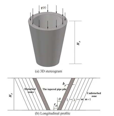
Fig.1 Pile-soil dynamic interaction model
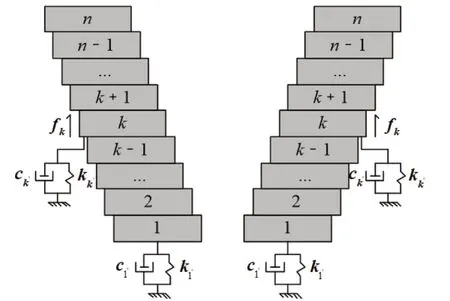
Fig.2 Simplified calculation model
(1) The tapered pipe pile is a vertical, elastic and one-dimensional hollow bar.
(2) The surrounding soil is boundless in the radial direction.It has a free top surface in the vertical direction where the normal and shear stresses are zero.
(3) The surrounding soil contacts perfectly with the pile shaft, suggesting continuous conditions of the stress and displacement at the pile-soil interface.
2.2 Dynamic equilibrium equation for the soil and the solution
Drawing on the plane strain model established by Novaket al.(1978) and Novak and Ella (1978), the dynamic equilibrium equation for the longitudinal vibration of the surrounding soil can be given as
The solution for Eq.(1) is
whereI0(s k,jr) andK0(s k,jr) denote the modified Bessel functions;Ak,jandBk,jare undetermined constants.
The shear stress of the soil can be written as
Whenj=m+1 , Eqs.(1), (2) and (3) are appropriate for the outmost soil zone.As the soil displacement decays to zero at horizontal infinity,Bk,m+1= 0.According to the definition, the shear complex stiffness at the contact surface of themth and (m+1)th zones can be expressed as
When 1≤j≤m, Eqs.(1), (2) and (3) are appropriate for the disturbed soil zones.The shear complex stiffness at the outside of thejth zone is derived as
It can be obtained from Eq.(5) that
From Eq.(5), the shear complex stiffness at the outside of the (j-1)th zone (i.e., the inside of thejth zone) can be obtained as
Substituting Eq.(6) into Eq.(7), the relationship betweenKk,jandKk,j+1can be established.Then, the shear complex stiffness at the inside of the first zone(i.e., the pile-soil interface),Kk,1, can be derived by the recursive method.
2.3 Dynamic equilibrium equation for the pile and the solution
whereEpk,Apkandρpkrepresent the elastic modulus,cross-sectional area and density of thekth pile segment,respectively.
The initial conditions of the pile are given as
The boundary conditions at the pile head and pile tip can be respectively given as
Applying the Laplace transform to Eq.(8) and combining with Eqs.(9) and (10), it can be derived that
wheres=iω;U k(z,s) denotes the Laplace transform ofu k(z,t);Vpkis longitudinal wave velocity of the pile.
It can be derived by solving Eq.(13) that
The impedance function at the top of thekth pile segment can be obtained as
wherekhdenotes the length of thekth segment;kφis determined by
whereZkbis the impedance function at the bottom of thekth pile segment.
The interaction between two adjacent pile segments is shown in Fig.3.At the bottom of thekth pile segment,the inner side is in contact with the (k-1)th pile segment while the outer part is directly contacted with the (k-1)th soil layer.The vertical support of the surrounding soil is simulated by the Voigt model.The relationship between the impedance function at the head of the (k-1)th segment and that at the bottom of thekth segment is established as follows.
Assume that each pile segment is a solid column and the bottom of thekth pile segment (a circular section with a radius ofkr) is entirely placed on the (k-1)th soil layer.The dynamic interaction at the contact surface is simulated by the Voigt model with a spring constant ofkkand a viscosity coefficient ofck.In the same way,the dynamic interaction between the circular section with a radius ofrk1-and the (k-1)th soil layer is also simulated by the Voigt model.The corresponding spring constant and viscosity coefficient are denoted bykk′-1andck′1-, respectively.The spring constant and viscosity coefficient that represent the dynamic interaction between the shaded ring pile and the (k-1)th soil layer are denoted bykk′, andkc′, respectively.The stress equilibrium at the contact surface is presented in Fig.3(c), wherePk(t) andPk-1(t) are axial forces of thekth and (k-1)th pile segments acting on the contact surface, respectively.Pk′(t) is the normal force developed at the interface of the shaded annular section with the (k-1)th soil layer.The aforementioned spring constants and viscosity coefficients can be derived as follows according to Lysmer and Richart (1966).
whereνk-1,1denotes the shear wave velocity of the 1st ring-shaped zone in the (k-1)th soil layer.
Pk(t),Pk-1(t) andPk′(t) can be respectively expressed as
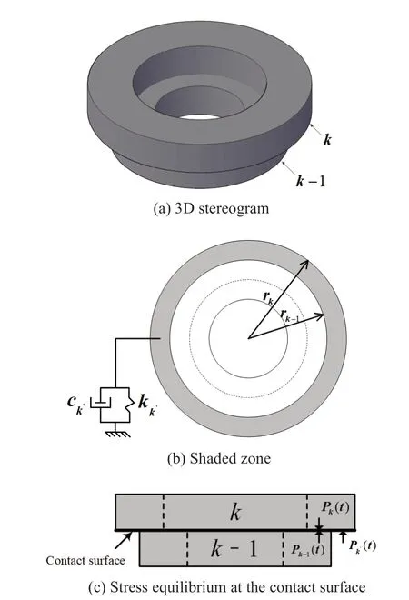
Fig.3 Interaction between two adjacent pile segments
From the stress equilibrium condition on the contact surface,
Then the normal forcePk′(t) can be derived as
According to Eqs.(23) and (25),
The continuous conditions of displacement and stress on the contact surface presented in Fig.3(c) are
whereu kb(z,t) andu(k-1)a(z,t) denote the displacement at the bottom of thekth pile segment and that at the top of the (k-1)th pile segment, respectively.
The following can be derived when the Laplace transform is imposed on Eqs.(28) and (29).
whereZ(k-1)adenotes the impedance functions at the top of the (k-1)th pile segment.
Likewise, the Voigt model is relied on in dealing with the dynamic interaction between the bottom soil and the pile tip.The corresponding parametersk1′andc1′can be determined following a similar approach as mentioned above.More specifically, a solid pile segment with a radius ofrcb, recorded as the 0th pile segment here, is assumed to exist at the bottom of the pile.Then,k1′andc1′can be obtained from Eqs.(23) and (25) as follows
wherebG,bρandbνare shear modulus, density and Poisson’s ratio of the bottom soil, respectively.
Then, the impedance function at the pile tip can be derived as
According to Eqs.(15), (16), (30) and (33) and together with the recursive method, the impedance function at the pile head,Zna, can be obtained.Further,its real and imaginary parts can be separated as follows
whereKnaandCnadenote the dynamic stiffness and damping, respectively.
3 Parameter selection and verification
The established solution is compared with the existing solutions to verify its reliability.The parameters used are as follows unless otherwise stated:Hp= 10 m,bp= 0.1 m,θ= 1°,rcb= 0.15 m,ρp=2500kg/m3,vp= 3600 m/s,Gb= 18 MPa,ρb= 1800kg/m3, andvb= 0.4.The density of the surrounding soil is 1800 kg/m3.The disturbance range isrd= 0.2 m.The shear wave velocity of the soil at the outmost zone is 100 m/s and is assumed to increase to 150 m/s radially inwards in a linear way for simplicity although any form of variation can be simulated by the proposed solution.In this research, the ratio of shear wave velocity of the soil in the innermost zone to that in the outmost zone,denoted byq, is employed to express the soil disturbance degree.Obviously,q>1 means that the soil is hardened,q<1 means that the soil is softened, andq=1 indicates that the soil is radially homogeneous.
3.1 Effect of the number of vertical ring-shaped zones (m) and the number of pile segments (n) on the displacement impedance
When establishing the pile-soil dynamic interaction model, the disturbed soil area is divided intomzones in the radial direction and the pile is divided intonsegments in the vertical direction.As a result, the calculation accuracy is controlled by the precision of the discretization, i.e., the value ofmandn.
The influence ofmandnis shown in Figs.4 and 5,respectively.Both the dynamic stiffness and the dynamic damping tend to be convergent asmandnincrease.After reaching a threshold value (m=20,n=100 in this case),further increase ofmandnhave almost no influence on the calculated curves.In light of this,mis given a value of 20 andnis given a value of 100 for the parametric study.
3.2 Verification
Let the wedge angleθ=0 °, the present solution can be degenerated into that for the constant-section pipe pile.When the inner radius is zero, the present solution can be degenerated into that for the tapered pile.The aforementioned degenerated solutions are compared with the solutions of Yang (2009) and Gaoet al.(2017),respectively.The results are given in Fig.6.The calculated curves derived from these two degenerated solutions agree well with the existing solutions, demonstrating the reliability of the present solution.Then, the comparison between the present solution and that neglecting the vertical support of the surrounding soil is portrayed in Fig.7.Once the vertical support of the surrounding soil is considered, both the dynamic stiffness and dynamic damping of the pile become higher, which indicates that it is a factor worthy of consideration when analyzing the dynamic characteristics of the tapered pipe pile.
4 Parametric study
4.1 Coupling effect of the pile parameters and the vertical support of the surrounding soil
The coupling effect of the pile parameters (wall thickness, inner radius, wedge angle and longitudinal wave velocity) and the vertical support of the surrounding soil on the displacement impedance of the tapered pipe pile is discussed in this section.The results are shown in Figs.8-11.

Fig.4 Effect of the number of vertical ring-shaped zones (m) on the displacement impedance
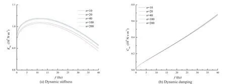
Fig.5 Effect of the number of pile segments (n) on the displacement impedance
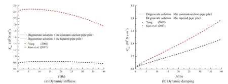
Fig.6 Comparison of the degenerated solution with the solutions of Yang (2009) and Gao et al. (2017)
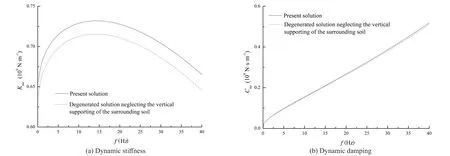
Fig.7 Comparison of the present solution with the degenerated solution neglecting the vertical support of the surrounding soil
4.1.1 Wall thickness
During the analysis,bpis assigned as 0.05 m, 0.1 m and 0.15 m, respectively.Meanwhile, the inner radius of the pile remains unchanged.The coupling effect of the wall thickness and the vertical support of the surrounding soil on the displacement impedance of the pile is presented in Fig.8, where Case A (B) indicates that the vertical support of the surrounding soil is neglected (considered).Comparing the curves for Case B with those for Case A, one can derive that the dynamic stiffness is increased when the vertical support of the surrounding soil is considered and the increasing degree is increased for increasing frequency.Asbpincreases, the dynamic stiffness gradually increases but the increasing rate decreases for increasing frequency.In addition, the increase of the dynamic stiffness driven by the vertical support of the surrounding soil is slightly increased for increasingbp.On the other side, the dynamic damping is also increased due to the consideration of the vertical support of the surrounding soil and this phenomenon can be more easily observed for a higher frequency.With the increase ofbp, the dynamic damping is increased but the increasing rate is gradually decreased.During this process, the vertical support of the surrounding soil plays a greater role in improving the dynamic damping of the pile.This means that an appropriate increase in the wall thickness can improve the ability of the tapered pipe pile to resist vertical deformation and vibration.In addition,the consideration of the vertical support of the surrounding soil is more in line with the actual situation.
4.1.2 Inner radius
The coupling effect of the inner radius of the tapered pipe pile and the vertical support of the surrounding soil on the displacement impedance of the pile is presented in Fig.9.The change of the inner radius of the tapered pipe pile is reflected by the variation ofrcb, i.e., the inner radius at the pile tip.During the analysis,rcbis taken as 0.1 m, 0.15 m and 0.2 m, respectively.The dynamic stiffness and damping gradually increase asrcbincreases.During this process, the increase of the dynamic stiffness and damping caused by the vertical support of the surrounding soil becomes more obvious.
4.1.3 Wedge angle
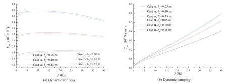
Fig.8 Coupling effect of the wall thickness and the vertical support of the surrounding soil on the displacement impedance
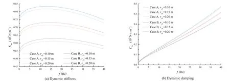
Fig.9 Coupling effect of the inner radius and the vertical support of the surrounding soil on the displacement impedance
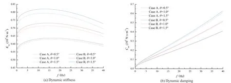
Fig.10 Coupling effect of the wedge angle and the vertical support of the surrounding soil on the displacement impedance
The coupling effect of the wedge angle and the vertical support of the surrounding soil on the displacement impedance of the pile is presented in Fig.10.In the process of research, the wedge angleθis taken as 0.5°, 1.0° and 1.5°, respectively.For increasingθ, the dynamic stiffness (damping) is gradually increased, indicating an enhancement in the deformation(vibration) resistance capacity of the tapered pipe pile.In addition, the dynamic stiffness (damping) is more notably increased by the vertical support of the surrounding soil during this process.
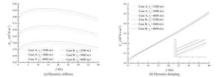
Fig.11 Coupling effect of the longitudinal wave velocity and the vertical support of the surrounding soil on the displacement impedance
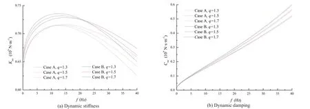
Fig.12 Coupling effect of the hardening degree and the vertical support of the surrounding soil on the displacement impedance
4.1.4 Longitudinal wave velocity
When investigating the influence of the longitudinal wave velocity of the pile,vpis taken as 3200 m/s, 3600 m/s and 4000 m/s, respectively, and the results are presented in Fig.11.The dynamic stiffness is notably increased asvpincreases.In contrast,vpshows a far less obvious impact on the dynamic damping.In addition, the increase of the dynamic stiffness (damping) caused by the vertical support of the surrounding soil is found to remain almost unchanged with the variation ofvp.
4.2 Coupling effect of the construction disturbance and the vertical support of the surrounding soil
In this partition, the coupling effect of the construction disturbance, commonly depicted by the hardening or softening of the soil, and the vertical support of the surrounding soil is investigated.The corresponding results are presented in Figs.12-15.
4.2.1 Hardening degree
During the analysis,qis taken as 1.3, 1.5 and 1.7,respectively.The other parameters remain the same with those assigned in Section 3.The coupling effect of the hardening degree and the vertical support of the surrounding soil is illustrated in Fig.12.For the curves corresponding to Case A, there exists a critical frequency (12 Hz in this case) below (above) which the dynamic stiffness is increased slightly (decreased obviously) for increasing hardening degree.The critical frequency becomes higher (22 Hz in this case) when the vertical support of the surrounding soil is taken into account.Meanwhile, the increase (decrease) of the dynamic stiffness below (beyond) the critical frequency becomes more (less) notable.Furthermore, the increase in the dynamic stiffness due to the vertical support of the surrounding soil is increased significantly with the increase of the hardening degree.The dynamic damping increases with the increasing rate decreases as the hardening degree increases.In addition, the influence of the vertical support of the surrounding soil exhibits negligible variation during this process.

Fig.13 Coupling effect of the hardening range and the vertical support of the surrounding soil on the displacement impedance
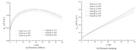
Fig.14 Coupling effect of the softening degree and the vertical support of the surrounding soil on the displacement impedance
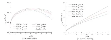
Fig.15 Coupling effect of the softening range and the vertical support of the surrounding soil on the displacement impedance
4.2.2 Hardening range
For the purpose of portraying the coupling effect of the hardening range and the vertical support of the surrounding soil,qis taken as 1.5 anddris taken as 0.1 m, 0.2 m and 0.3 m, respectively.The corresponding results are shown in Fig.13.For increasing the hardening range, the dynamic stiffness below the critical frequency exhibits a slight increase while that beyond the critical frequency gradually decreases when the vertical support is not considered.Unlike that in Fig.12, the critical frequency of the curves corresponding to Case B remains the same with that corresponding to Case A.The consideration of the vertical support of the surrounding soil results in a more (less) notable increase(decrease) in the dynamic stiffness below (beyond) the critical frequency.In addition, the increasing degree of the dynamic stiffness contributed by the vertical support of the surrounding soil becomes higher as the hardening range increases.The dynamic damping is increased as the hardening range increases.During this process, the influence of the vertical support of the surrounding soil exhibits negligible variation.
4.2.3 Softening degree
The coupling effect of the softening degree and the vertical support of the surrounding soil is illustrated in Fig.14.As the softening degree increases, the dynamic stiffness below the critical frequency is decreased slightly while that beyond the critical frequency is increased as the increasing rate decreases.The consideration of the vertical support of the surrounding soil leads to an increase in the critical frequency (from 16 to 23 Hz in this case) and a more (less) notable decrease (increase)in the dynamic stiffness below (beyond) the critical frequency.The dynamic damping is decreased and the decreasing rate gradually decreases as the softening degree increases.In addition, the increase of the dynamic damping driven by the vertical support of the surrounding soil is almost unchanged as the softening degree increases.
4.2.4 Softening range
The coupling effect of the softening range and the vertical support of the surrounding soil is illustrated in Fig.15, whereqis taken as 0.8 and the softening rangedris taken as 0.1 m, 0.2 m and 0.3 m, respectively.For the increasing softening range, the dynamic stiffness is decreased and the decreasing degree is gradually increased for increasing frequency.During this process,the increase of the dynamic stiffness driven by the vertical support of the surrounding soil becomes less notable.In addition, the dynamic damping is decreased and the decreasing degree is decreased for the increasing softening range.In the process, the increase in the dynamic damping caused by the vertical support of the surrounding soil is almost unchanged.
5 Conclusions
An analytical solution is established to portray the longitudinal vibration of a tapered pipe pile with the consideration of the vertical support of the surrounding soil and construction disturbance.Comparisons with other solutions are conducted to verify its reliability.Parametric analysis concerning the coupling effect of the pile parameters, construction disturbance and the vertical support of the surrounding soil draws the following conclusions:
(1) The dynamic stiffness and damping of the pile can be improved to a certain extent by the consideration of the vertical support of the surrounding soil, indicating that it is an important consideration when analyzing the dynamic characteristics of the tapered pipe pile.
(2) The dynamic stiffness and damping are increased as the wall thickness, inner radius, wedge angle and longitudinal wave velocity of the tapered pipe pile increase, which means an enhancement in the ability of the pile to resist vertical deformation and vibration.
(3) For increasing the hardening degree (range),the dynamic stiffness below the critical frequency is increased slightly while that beyond the critical frequency is decreased.The dynamic damping increases within the whole frequency range.The critical frequency increases (remains unchanged) when the vertical support of the surrounding soil is taken into consideration.For increasing the softening degree, the dynamic stiffness below the critical frequency is decreased slightly while that beyond the critical frequency is increased.The dynamic damping decreases during this process.Meanwhile, the critical frequency increases when allowing for the effect of the vertical support of the surrounding soil.The dynamic stiffness and damping are gradually reduced as the softening range increases.
(4) The increase in the dynamic stiffness and damping caused by the vertical support of the surrounding soil becomes more notable for increasing wall thickness,inner radius, wedge angle or longitudinal wave velocity of the tapered pipe pile, i.e., the vertical support of the surrounding soil plays a more obvious role in the longitudinal vibration of the tapered pipe pile.As the hardening (softening) degree or range increases, the influence of the vertical support of the surrounding soil on the dynamic stiffness is found to become more (less)notable while that on the dynamic damping is almost not affected.
(5) In actual engineering practice, the wall thickness,inner radius, wedge angle and longitudinal wave velocity of the tapered pipe pile can be appropriately increased to improve its resistance capacity to longitudinal deformation and vibration.
Acknowledgement
This work is supported by the National Natural Science Foundation of China under Grant No.51808190,the Central Government Guides Local Science and Technology Development Fund Projects under Grand No.XZ202301YD0019C, the Foundation of Key Laboratory of Soft Soils and Geoenvironmental Engineering (Zhejiang University), Ministry of Education under Grand No.2022P04, and the Central University Basic Research Fund of China under Grant No.B220202017.
 Earthquake Engineering and Engineering Vibration2024年1期
- Earthquake Engineering and Engineering Vibration的其它文章
- A novel mitigation measure for normal fault-induced deformations on pile-raft systems
- Time-domain dynamic constitutive model suitable for mucky soil site seismic response
- Finite element model updating for structural damage detection using transmissibility data
- Experimental study on seismic reinforcement of bridge foundation on silty clay landslide with inclined interlayer
- Liquefaction susceptibility and deformation characteristics of saturated coral sandy soils subjected to cyclic loadings - a critical review
- Resilient performance of self-centering hybrid rocking walls with curved interface under pseudo-static loading
