Active-passive radial-additive friction stir repairing of mechanical hole out of dimension tolerance of AZ31 magnesium alloy
Hu Liu ,Zhenlei Liu ,Shude Ji ,Yumei Yue ,Zhio Dong ,Chnglong Chen
aCollege of Aerospace Engineering, Shenyang Aerospace University, Shenyang 110136, China
b State Key Laboratory of Advanced Welding and Joining, Harbin Institute of Technology, Harbin 150001, China
Abstract In order to avoid the depth increasing of repaired hole and eliminate the super-fine grain band in stir zone by radial-additive friction stir repairing (R-AFSR),a solid-state repairing technique of active-passive radial-additive friction stir repairing (AP-RAFSR) assisted by the truncated cone-shaped filling material was proposed in this study.The mechanical hole out of dimension tolerance of AZ31 magnesium alloy was chosen as the repaired object.The results indicated that the AP-RAFSR process rather than the R-AFSR process avoided the kissing bond in the bottom of the repairing interface under the condition of the tool pin length equal to the height of the standard mechanical hole.The continuously-distributed and large-length super-fine grain bands were eliminated in the stir zone by AP-RAFSR.The maximum tensile and compressive-shear strengths of repaired hole by AP-RAFSR reached 190.6 MPa and 138.9 MPa at 1200 rpm respectively,which were equivalent to 97.7% and 89.6% of those of the standard mechanical hole.This AP-RAFSR process assisted by the truncated cone-shaped filling material provides a new technique to obtain a no-depth-increasing,defect-free and high-strength repaired mechanical hole.
Keywords: Active-passive radial-additive friction stir repairing;Mechanical hole out of dimension tolerance;Numerical simulation;Microstructure;Mechanical properties.
1.Introduction
The mechanical hole is important for the connection of metal components,but the damages such as dimension deviation inevitably occur during the process of production and service [1].The damaged mechanical hole cannot satisfy the assembly requirement,and the scrapping of the whole metal component causes economic loss.Consequently,the repair of the damaged mechanical hole is a beneficial method to extend the service life of metal components and save the cost.
Li et al.[2]repaired the damaged mechanical hole by applying the polymer coating with a suitable thickness on the damaged wall,and then the polymer coating cured under suitable thermal treatment.However,the inferior quality of the polymer coating,as well as the inappropriate conditions of cure may lead to the coaxial error of repaired hole,thereby weakening the quality of the repaired hole.Gas tungsten-arc (GTA) was used to successfully repair flange bolt hole with great reproducibility by Lee et al.[3].Whereas,inevitable pores and microcracks are generated in joint,which indicates that the fusion welding is not optimum to repair damages in metal structures.In fact,the damaged mechanical hole can be considered as a volumetric defect.As reported by Meng et al.[4],friction stir repairing (FSR) not only has the advantages of nonpollution,low deformation and high strength but also avoids the fusion welding defects such as pores and hot cracks,which has been adopted as a green technology to realize the high-quality repair of volumetric defects.This technique is a modification of FSW,which is originally developed for joining difficult-to-fusion welded aluminum alloys [5–15].
The researches on the repair of volumetric defects are mainly based on the idea of using the filling material (FM),and some researchers repair the mechanical hole by using consumable tool that can be considered as FM.Friction hydro-pillar processing(FHPP)was adopted by Hattingh et al.[16]to repair incorrectly drilled hole by a column-shaped consumable pin,but the flaws were discovered near the interface of consumable pin and hole wall due to the low forging force.Friction plug welding (FPW) [17]and friction taper plug welding (FTPW) [18]were proposed to fill the hole by using the conical-shaped consumable pin.Notably,the forging force acting on conical-shaped pin can divide into two forces which are parallel to the interface and perpendicular to the interface respectively,and the perpendicular force can promote the atom diffusion and then the interface bonding effect.Moreover,filling friction stir welding (FFSW) [19]has been used to repair the keyhole by using a non-consumable shoulder for improving the forging force and heat input.Although the above-mentioned methods based on consumable tool are available for the volumetric repair,lacking of bonding and incomplete filling defects are easily formed because of the deformable pin.As a result,the non-consumable tool with an additional FM attracts the interest of researchers.Reimann et al.[20]used friction stir spot welding (FSpW) to repair keyhole assisted by the cylindrical-shaped filling material,and the repair process was controlled by the relative movement of separated tool shoulder and tool pin.In addition,additive friction stir deposition was explored by Griffiths et al.[21]for the repair of through hole,which continuously deposited material into the hole through a robust material feeding mechanism.Nevertheless,the complex components assembly limits the application of FSpW and additive friction stir deposition.Self-refilling friction stir welding (SRFSW) proposed by Zhou et al.[22],based on the non-consumable tool with pin,adapted to repair keyhole by adding FM layer-by-layer,but a keyhole with a small depth was still left after repairing.Thus,active-passive filling friction stir repairing (A-PFFSR)was put forward by Ji et al.[23]to admirably repair keyhole through the non-consumable and pinless tool.
The mechanical hole out of dimension is a type of damaged hole and can be repaired by the above-mentioned methods evolved from FSR,but an extra re-drill process is required after repairing.Hence,a novel technology called radialadditive friction stir repairing (R-AFSR) is put forward by Song et al.[24],which can realize one-step repair of the mechanical hole.Nonetheless,in order to get an effective bonding at the bottom of interface between FM and base material (BM) (the FM/BM interface),the pin needs pierce the FM in the repair process and a deeper repaired hole is generated,so this technique is not suitable for the repairing of blind hole.Additionally,the continuously-distributed and large-length super-fine grain band in the stir zone (SZ) is formed due to the grinding between the FM and the BM,which is harmful to the uniformity of microstructure of repaired region by R-AFSR.
Therefore,in order to realize the no-depth-increasing repaired hole and eliminate the super-fine grain band in SZ during R-AFSR,a new process named active-passive R-AFSR(AP-RAFSR) assisted by the truncated cone-shaped FM was adopted to repair the mechanical hole out of dimension in the present study.The numerical simulation method was used to analyze temperature field during the repairing process.Besides,the formations,mechanical properties and fracture characteristics of the repaired holes were mainly investigated in detail.
2.Materials and methods
2.1. Experimental procedure
The AP-RAFSR process is divided into two stages including active FSR(A-FSR)stage and passive-FSR(P-FSR)stage,as shown in Fig.1.The diameter and depth of standard mechanical hole are supposed to beΦ1and H1.Before A-FSR,a pinless tool with six-spiral-groove is chosen and its diameterΦ2is larger thanΦ1(Fig.1a).At the A-FSR stage,this pinless tool is used to fill the bottom part of the mechanical hole out of dimension tolerance with the materials surrounding the upper part of the hole (Fig.1b),which makes the hole to be a cylindrical hole.After A-FSR,the diameter and depth of this cylindrical hole respectively become larger and smaller,and the corresponding values areΦ2and H2(Fig.1c).Before P-FSR,the truncated cone-shaped FM with a diameter ofΦ3at the top andΦ2at the bottom is put into the hole to be repaired (Fig.1d).In order to avoid the thickness thinning of the repaired region and improve the repair effect,the height of FM is larger than H2.At the P-FSR stage,the tool pin with the diameter ofΦ1and the length of H1is used to attain the repaired hole,and the tool dwells for a few seconds when the tool shoulder just contacts with the top surface of the cylindrical hole (Fig.1e).After the P-FSR stage,the FM and the BM are firmly bonded under the combined effects of friction heat,stirring and forging provided by the rotational tool,and a repaired hole with the diameter and depth equal to those of standard mechanical hole is obtained (Fig.1f).

Fig.1.Sketch maps of AP-RAFSR process: (a) before A-FSR,(b) during A-FSR,(c) after A-FSR,(d) before P-FSR,(e) during P-FSR,(f) after P-FSR.
The BM was AZ31 magnesium alloy sheet with a thickness of 3.5 mm,and the FM was the same material as BM.The chemical composition and mechanical properties are shown in Table 1.The tool in Fig.2a was used to perform the AFSR stage and the tool in Fig.2b was used to perform the P-FSR stage.The special dimensions of rotational tool and repaired holes at different stages are listed in Table 2.For the AP-AFSR process,the formation of the FM/BM interface determines the mechanical properties of repaired hole.The material mixing and heat input are the key factors affecting the FM/BM interface formation,and these two factors are mainly affected by rotational speed,plunge speed and dwelling time.The process parameters are listed in Table 3.In fact,the rotational speed and the dwelling time have a larger influence on the heat input compared with the plunge speed,and the material mixing is mainly decided by the rotational speed rather than the dwelling time.Therefore,the rotational speed was chosen as a variable in this study.In Table 3,the variable rotational speeds,the constant plunge speed and the constant dwelling time were designed according to the studies of Song et al.[24]and Zuo et al.[25].

Table 1Chemical compositions and mechanical properties of AZ31 magnesium alloy (wt.%).
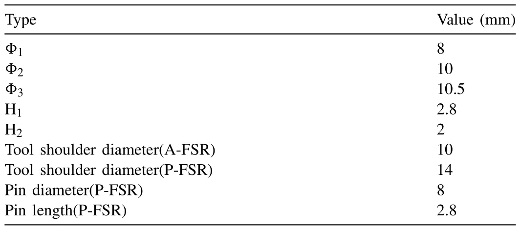
Table 2Special dimensions of rotational tool and repaired holes at different stages.

Table 3Process parameters during repairing.
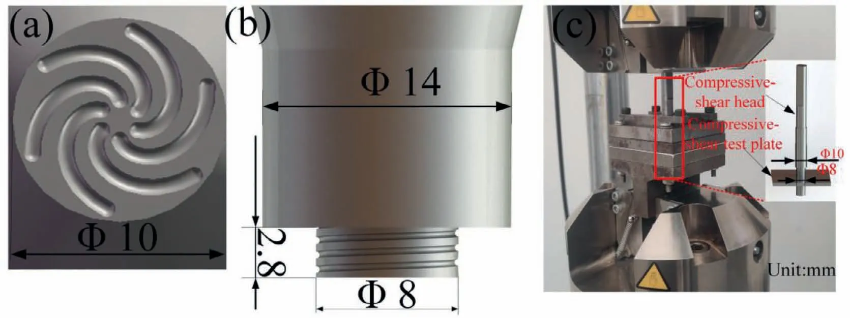
Fig.2.Schematic diagrams of tools during (a) A-FSR and (b) P-FSR;(c) compressive-shear test.
The repair experiments were performed by the FSW machine.A wire-cutting machine was used to cut samples for observing metallurgical features and testing mechanical properties.After burnished and polished,the specimens were etched by the picric acid solution (4.2 g picric acid,10 ml H2O,10 ml acetic acid,and 70 ml ethanol),and the cross section and microstructure were observed by the optical microscope (OM).The microhardness test was finished under the load of 200 g for 10 s using the Vickers hardness tester.The compressive-shear test was carried by a selfdesigned compress shear device shown in Fig.2c.Tensile and compressive-shear tests were completed at room temperature with 2 mm/min by the universal tensile testing machine.Three tensile and compressive-shear tests were carried out for each group of parameters,and the average values were calculated to evaluate the repair quality of the repaired hole.The fracture morphologies of tensile and compressive-shear specimens were observed by the scanning electron microscope(SEM).
2.2. Finite element model of AP-RAFSR
The three-dimensional finite element model of AP-RAFSR was established by the MSC.Marc software.The dimension of the simulated model was 50×50×3.5 mm,and this mode had 45,306 nodes and 41,040 elements.The mesh was built by Lagrange method and the eight-node hexahedral element(HEX-8) was used in this simulation.A non-uniform mesh was used to divide the model,which meant that the smaller mesh was used near the repaired region and the larger mesh was used far away from the repaired region (Fig.3a).The thermal properties of the AZ31 magnesium alloy in different temperatures were determined according to the study of Lee et al.[26],as shown in Fig.3b [26].Moreover,the density was 1780 kg/m3.The initial temperature and ambient temperature of the model were set as 20 °C.The convection heat dissipation coefficient of the plate surface in contact with air was set as 30 W/ (m2· °C),and this coefficient of the plate surface in contact with the fixture and the cushion plate was set as 200 W/ (m2· °C).In the simulation of AP-RAFSR,the main welding heat sources are composed of three parts,including the friction heats of the plate and shoulder,the plate and pin side and the plate and pin bottom.The heat production used in this study was according to the research of He et al.[27]and expressed as:

Fig.3.Numerical simulation process: (a) simulation model,(b) thermal properties of AZ31 magnesium alloy [26]and (c) schematic diagram of temperature measurement positions.
WhereQis the rate of heat generation,ωis the angular velocity of the tool,R1is the radius of the tool shoulder,R2is the radius of the tool pin,His the height of pin,μis the friction coefficient,andPis the tool plunge pressure.
The heat sources were applied to the finite element model through the flux subroutine written in the fortran language,and the temperature field was obtained after nonlinear calculation.Birth-death element was used to simulate the movement process of metal materials under A-FSR and P-FSR stages,and the A-FSR and P-FSR stages respectively contained 5 s and 10 s for the pre-heating.The K-type thermocouples were used to measure the temperature.The points P1 and P2 selected for temperature measurement were 3 mm and 8 mm away from the edge of the shoulder,as shown in Fig.3c.The actual measured results and the simulation results were compared to verify the accuracy of the finite element model in this study.
3.Results and discussion
3.1. Surface morphology
Fig.4 shows the top surface morphologies of the mechanical hole at different stages of AP-RAFSR.The mechanical hole to be repaired is shown in Fig.4a.The flash is formed around the hole because the material is extruded by the pinless tool after A-FSR,as shown in Fig.4b.Besides,the materials at the top part of the hole wall are filled into the bottom of the hole during A-FSR,and the diameter of repaired hole after A-FSR is increased to 10 mm.Before P-FSR,the FM is put into the repaired hole and an interface appears between the outer wall of FM and the inner wall of the repaired hole(Fig.4c).The diameter of the repaired hole after P-FSR is restored to 8 mm,and the original interface disappears.Simultaneously,the flash in Fig.4d is bigger than that after A-FSR in Fig.4b.

Fig.4.Surface morphologies of mechanical hole at 1200 rpm: (a) before A-FSR,(b) after A-FSR,(c) before P-FSR and (d) after P-FSR.
3.2. Thermal analysis
Fig.5 shows the temperature curves of the observation points in numerical simulation and experimental under APRAFSR.Notably,the temperature increases rapidly at first and then decreases with the retraction of the rotational tool during repairing.The peak temperatures of point P1 obtained by numerical simulation are 189.4 °C under A-FSR and 285.8 °C under P-FSR (Fig.5a),and the corresponding values by experiment are 187.1 °C and 281.9 °C (Fig.5b).The peak temperatures of point P2 obtained by numerical simulation are 169.0 °C under A-FSR and 257.4 °C under P-FSR,and the corresponding values by experiment are 165.3 °C and 252.2 °C.The relative errors of peak temperatures for point P1 between simulation and experiment results are about 1.22% under A-FSR and 1.58% under P-FSR,and they for point P2 are 2.02% under A-FSR and 2.18% under P-FSR.These relative error values are all within 5%,indicating that the numerical simulation model established in the present study is reasonable.
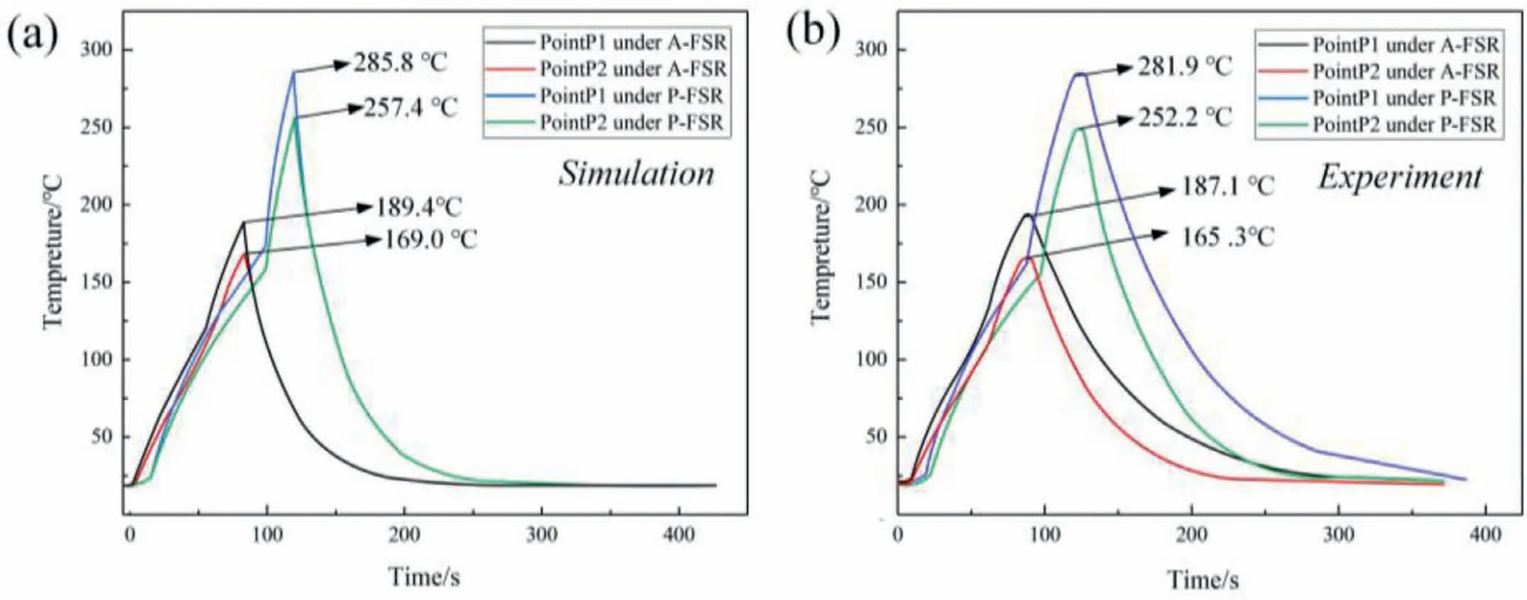
Fig.5.Temperature cycles of observation points at 1200 rpm under AP-RAFSR by (a) simulation and (b) experiment.
Fig.6 shows the temperature fields of the top surface and cross section of repaired region at the plunging stages of the A-FSR and the P-FSR.The temperature field is symmetrical and the temperature gradient near the rotational tool is higher than that far away from the tool.The high temperature area under A-FSR is different from that under P-FSR due to the difference of the rotational tool,and the corresponding regions are respectively annulus and circular during A-FSR and P-FSR on the top surface,as shown in Figs.6a and b.Besides,the high temperature regions during A-FSR and PFSR respectively show a bathtub-shaped distribution (Fig.6c)and a funnel-shaped distribution (Fig.6d) on the cross section.Song et al.[24]found that the SZ presented a funnel shaped,which is consistent with the high temperature region distribution during P-FSR in the present study.
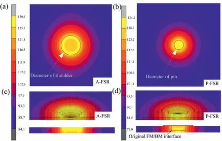
Fig.6.Temperature fields at 1200 rpm: (a) surface and (c) cross section at the plunging stage of A-FSR;(b) surface and (d) cross section at the plunging stage of P-FSR.
The temperature cycles of points M1 and M2 are displayed in Fig.7.Points M1 and M2 are respectively located at the center of the repaired hole and the original FM/BM interface,and these two points are both 2.8 mm away from the top surface of the repaired hole.The main heat resource is generated by the friction between the welding tool and metal material [28,30],so the corresponding larger friction region causes higher heat generation.The temperature cycles during A-FSR and P-FSR are both divided into three stages of pre-heating,plunging and dwelling.The friction only happens between the bottom of rotational tool and the workpiece at the pre-heating stage,and the friction region gradually grows with the plunge of tool and the maximum friction region appears at the dwelling stage.Therefore,the heat rate of each stage is not consistent due to the difference of heat accumulation rate.Besides,the rate of heat generation is constant at the dwelling stage in simulation,thereby causing the larger heat accumulation rate and the higher heat rate than the pre-heating stage and plunging stage.The peak temperatures of the repair region increases with the increase of rotational speed[29].The peak temperatures at point M1 at 1200 rpm are 245.6 °C under A-FSR and 381.4 °C under P-FSR,while the temperatures respectively increase to 307.9 °C and 496.9 °C at 1400 rpm.The heat generated locally causes the temperature gradient [29],so the temperature at the FM/BM interface is lower than that at the center of the repaired hole.The peak temperatures for point M2 are respectively 270.1 °C under A-FSR and 415.6 °C under P-FSR at 1400 rpm,which are 87.7% and 83.6% of those of point M1.The heat input is the main factor influencing the interface formation,and these temperature distribution features mean that the defects such as kissing bond easily appear at the bottom of the FM/BM interface.
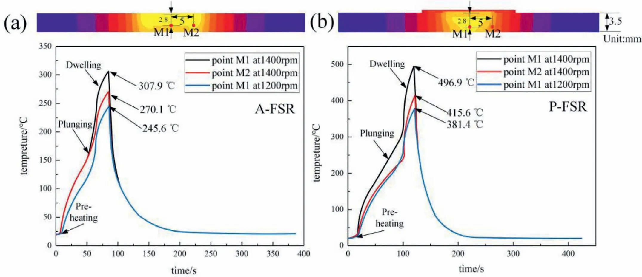
Fig.7.Temperature cycles of point M1 and point M2 under (a) A-FSR and (b) P-FSR.
3.3. Microstructures of repaired region
Fig.8 displays the cross sections of the repaired holes under different repair conditions.The sound repair regions without thickness reduction and inner defects are obtained by AP-RAFSR,as shown in Figs.8a-d,and the depth of the repaired hole remains 2.8 mm.In addition,in order to illustrate the advantages of AP-RAFSR,the R-AFSR experiment was also performed under the same parameters of the rotational speed of 1400 rpm,the plunge speed of 2 mm/min,and the dwelling time of 20 s.In the study of Song et al.[24],the length of tool pin and the depth of hole to be repaired were 2.8 mm and 2.5 mm respectively,and the super-fine grain bands appeared in the sound repaired hole (Fig.8f).However,the corresponding values are both 2.8 mm during R-AFSR in this study.When the length of the tool pin is the same as the depth of the unrepaired hole,and the kissing bond appears at the bottom of the FM/BM interface (Fig.8e).In fact,the kissing bond is closely related to the material flow behavior during repairing,which is discussed in detail in the following part.
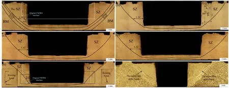
Fig.8.Cross sections of repaired holes: (a) 1000 rpm,(b) 1200 rpm,(c) 1400 rpm and (d)1600 rpm under AP-RAFSR;(e) 1400 rpm under R-AFSR;(f)1400 rpm under conventional R-AFSR[24].
The cross section of repaired hole is divided into four zones called SZ,thermo-mechanically affected zone(TMAZ),heat affected zone (HAZ) and BM (Fig.8a).The SZ widths at 2 mm away from the top surface of the repaired region under 1000,1200,1400 and 1600 rpm are 1.33,1.39,1.42 and 1.52 mm respectively (Figs.8a-d),and the corresponding value is 0.61 mm at 1400 rpm under R-AFSR in the present study (Fig.8e).With the increase of rotational speed,the material undergoes not only the lower flow resistance but also larger flow velocity,thereby enlarging the SZ [6].In addition,the A-FSR also helps to enlarge the SZ and is beneficial to eliminating the kissing bong in the repair region.
Fig.9 shows the microstructures of BM,HAZ and TMAZ at 1200 rpm.The microstructure of BM shows heterogeneous and equiaxed grains (Fig.9a).The grain size of HAZ is much larger than that of the BM due to the effect of heat input (Fig.9b) [13].The magnesium alloy has low stack-fault energy and low recrystallization temperature [32,34].The materials of TMAZ undergo dynamic recrystallization (DRX)by thermal cycle and indirectly mechanical stir provided by rotational tool,so the grain refinement occurs in the TMAZ[11,12].Similar to the results of Sahu et al.[36],the TMAZ are composed of equiaxed grains finer than those of HAZ(Fig.9c).
Fig.10 shows the microstructures of SZ at the rotational speed of 1200 rpm.Notably,DRX is the main mechanism for grain refinement [10,15].The severe plastic deformation of material happens during repairing and the grains are broken in the SZ under the strong stirring and shearing effects of the rotational tool [35],which increases the density of dislocations and causes more intensified dynamic recovery and recrystallization [37,40].The dislocations are located at lowangle grain boundaries (LAGBs),the deviation between adjacent subgrains increases and LAGB transforms into highangle grain boundaries (HAGBs) with the continuation of deformation,thereby forming fine grains [33].The relationship of grain size (d) and temperature (T) can be expressed as[33]:
Whered0is the initial grain size,k0is a constant,Qis the activation energy for boundary mobility,tis the time,andRis the gas constant.According to Eq.(2),the grain size increases with the increase of temperature.Besides,the material undergoes the intense stirring and shearing effects of the rotational tool,causing large plastic deformation and the constant DRX.Accordingly,the temperature,and the stirring and shearing effects of the rotational tool all determine the grain sizes of different areas in SZ.The value of grain size in different areas was calculated based on the linear intercept method similar to the study of Bagheri et al.[33].The grain size of SZ increases with the increase of distance from the edge of the repaired hole,and the grain sizes in areas B1and D1are 7.4 μm and 9.7 μm respectively (Figs.10b and d),and this tendency is similar to the study of Song et al.[24].The materials at the edge of the repaired hole are in contact with the rotational tool and undergo a more intense mechanical stirring effect of the rotational tool compared with the materials far away from the edge of the repaired hole.Therefore,the grain size difference between areas B1and D1presents that the stirring and shearing effects of rotational tool have a greater influence on grain size than temperature during repairing.Similarly,the grain size of SZ increases with the distance from the top surface of repaired hole increasing,and the grain sizes of areas A1,B1and C1are 5.8 μm,7.4 μm and 12.3 μm respectively (Figs.10a-c).
Fig.11a shows the microstructure of area A marked in Fig.8a under 1000 rpm.At the beginning of A-FSR stage,the materials of the upper part of the repaired region near the wall of hole are filled into the bottom of the hole,and then tightly contact with the pinless tool.The pinless tool provides a super large vertical force and super high flow velocity on both these filled materials and the BMs at the hole bottom.It is concluded that the interfaces between the filled materials and the BMs at the A-FSR stage are out-of-order under the violent material flow,and the material mixing and the atom diffusion bonding between the filled materials and the BMs are sufficient under the very large vertical force.Therefore,no repair interface appears at the bottom of the repaired region(Figs.8a-d),and this phenomenon is similar to the research of Ji et al.[23]during the A-PFFSR process.

Fig.11.Enlarged views of some areas in SZ: (a),(b) and (c) of areas A,B and C marked in Fig.8a;(d) the super-fine grain band under conventional R-AFSR[24].
Figs.11b-c show the discontinuously-distributed and verysmall-length super-fine grain bands in the repaired hole at the rotational speed of 1000 rpm.As reported by Song et al.[24],the violent grinding happened between the FM and the BM during the R-AFSR process,and the super-fine grain bands owning the continuously-distributed,large-length features appeared at the FM/BM interface (Fig.11d),which was harmful for the uniformity of microstructure in the SZ.In order to eliminate the super-fine grain band,Zuo et al.[25]added the stationary shoulder in the process of R-AFSR.The stationary shoulder provides extra-forging and sealedbarrier effects,which results in a large force perpendicular to the FM/BM interface and helps to avoid the grinding phenomenon.In the present study,the mechanism of the superfine grain band elimination is similar to that of the research of Zuo et al.[25].The diameter of the upper part of FM is slightly larger than the diameter of the mechanical hole to be repaired.After filling into the hole,the FM is closely attached to the wall of the hole to be repaired,and there is a relatively large pressure perpendicular to the FM/BM interface.This pressure is beneficial to preventing the relative movement and grinding between the FM and the BM when the rotational pin keeps plunging into the FM.Therefore,no obvious super-fine grain band is observed in Figs.8a-d.Certainly,it is difficult to completely avoid the relative motion between a small portion of FM/BM,because the relation between the FM and the BM before repairing is only tight contact rather than sufficient bonding.Therefore,the superfine grain bands are also formed in the SZ,but the distribution features are totally different from the study of Song et al.[24].
3.4. Material flow during P-FSR
Fig.12a shows the sketch map of material flow at the PFSR stage of AP-RAFSR process,which is similar to that in the R-AFSR process (Fig.12b).In general,the material constantly moves upward driven by the right-thread pin when the tool rotates clockwise during repairing [24],so an instantaneous cavity is formed at the bottom of the rotational pin.According to the law of minimum resistance,the materials below the shoulder easily flow downward to fill the instantaneous cavity due to the combined effects of the forging force from the rotational shoulder and the constraint of the surrounding hard material.Accordingly,the material flow cycle during repairing is formed,as displayed in Figs.12a and b,which is beneficial for the material mixing at the FM/BM interface.However,different from the P-FSR stage of APRAFSR process (Fig.12a),the pin with the 2.8 mm is the same length as the FM during the R-AFSR(Fig.12b),and the kissing bond appears at the original FM/BM interface(Fig.8e and Fig.12b).

Fig.12.Schematic diagrams of the material flow of (a) P-FSR and (b) R-AFR.
According to the research of solid-state repair technologies focusing on the FM/BM bonding [19,38],adequate heat input and material flow are the two key factors for high-quality interfacial bonding.Thus,there are two factors leading to the formation of kissing bands under R-AFSR (Fig.12b).Firstly,referring to the temperature field in Fig.7,the main heat source in the repair process is the tool shoulder,but the temperature gradient along the thickness direction leads to the insufficient heat at the bottom of the repaired hole and then the increase of material flow resistance during repairing [38].Secondly,the material flow which is mainly driven by cylindrical pin is extremely slow at the bottom of the FM/BM interface,so this interface bonding mainly depends on atomic diffusion and the strength of the FM/BM interface is insufficient.At the A-FSR stage of AP-RAFSR process,these materials at the bottom of repaired hole undergo adequate heat input and sufficient flow provided by the pinless tool,which contributes to an enlarged SZ and a well-bonding interface.
The depth of the damaged hole decreases after A-FSR and the pin length used in P-FSR is equal to the depth of the damaged hole before A-FSR,which can also make the pin pierce the FM.This ensures the sufficient material flow and the excellent material mixing at the bottom of FM/BM interface,and the height of repaired hole is equal to standard mechanical hole after the P-FSR stage.
3.5. Microhardness distribution
Fig.13 shows the positions of test points and the distributions of microhardness in the repaired region at different rotational speeds.With the increase of the distance from the edge of the repaired hole,the microhardness values at line A and line B decrease firstly,then slightly increases and finally tends to be stable.There is no strengthening phase in AZ31 magnesium alloy,so its microhardness is only related to grain size.Fine grain is associated with high microhardness [9,39].The grain size in the HAZ is the largest and the microhardness is the smallest [7,14];on the contrary,the grain size of SZ is the smallest and the microhardness is the biggest[8,31].Hence,the maximum microhardness of the repaired hole is 88.7 HV in SZ and the minimum is 52.1 HV in HAZ.The microhardness in TMAZ reaches 63.2 HV,which is slightly larger than the microhardness value of BM (59 HV) because the TMAZ owns finer grains compared with BM (Fig.9).With the increase of rotational speed,the heat input and the size of grains increase in repaired region,leading to a slight decrease of microhardness.

Fig.13.Microhardness distributions of repaired region.
3.6. Tensile and compressive-shear strength
The tensile test results of repaired hole are shown in Fig.14.The tensile strength of AP-RAFSR process first increases and then decreases with the increase of rotational speed,and the values are all larger than that of R-AFSR process in the present study at 1400 rpm.The maximum tensile strength of repaired hole is 190.6 MPa,reaching 97.7% of that of the standard mechanical hole at 1200 rpm.As reported by Song et al.[24],the maximum tensile strength of repaired hole under R-AFSR is 183 MPa at 1400 rpm,which is 93.8% of that of the standard mechanical hole,whereas in the present study it is only 78.5%of standard mechanical hole under the same rotational speed of 1400 rpm.Notably,the pin pierces the FM is very important to obtain a defect-free repaired hole for the R-AFSR (Fig.8f).However,the kissing bond easily appears at the bottom of the repaired hole when the pin does not pierce the FM (Fig.8e).
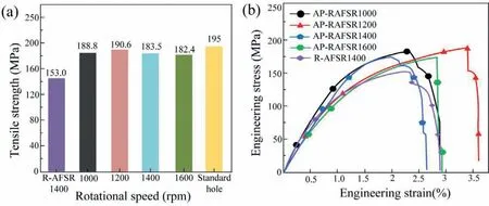
Fig.14.Tensile test results of the repaired hole under different rotational speeds: (a) tensile strength and (b) stress-strain curves.
Fig.15 shows the compressive-shear results and the loaddisplacement curves at different rotational speeds.With the increase of rotational speed,the compressive-shear strength of repaired hole has a tendency similar to the tensile strength.The maximum compressive-shear strength is 138.9 MPa at 1200 rpm,which is 89.6% of that of the standard mechanical hole,and the value is much higher than the maximum strength under R-AFSR reported by Song et al.[24].In fact,the tensile and compressive-shear strength of the repaired holes are affected by the bonding of the FM/BM interface.Low rotational speed may bring insufficient heat input,leading to the insufficient material flow and the weak bonding of the FM/BM interface,while high rotational speed may bring excessive heat input,leading to the severe coarsening-grains of the repaired region.Consequently,the tensile-compressive performance at the reasonable rotational speed of 1200 rpm is the highest when the rotational speed varies from 1000 to 1600 rpm.From Figs.8,12,14 and 15,it is concluded that the tool pin with the length larger than the height of FM is the key factor to avoiding the kissing bond and then obtaining the high-quality repaired hole.Compared with the R-AFSR,the AP-RAFSR process is more suitable for the engineering application about repairing the mechanical hole out of dimension tolerance,because the AP-RAFSR process can get defect-free repaired hole with the depth equal to that of standard mechanical hole.
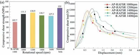
Fig.15.Compressive-shear test results of the repaired hole under different rotational speeds: (a) compressive-shear strength and (b) load-displacement curves.
3.7. Fracture features
The fracture paths and the fracture surface morphologies of the tensile samples are shown in Fig.16.The fracture paths of AP-RAFSR and R-FSR are obviously different.The cracks are generated at the hole wall under the tensile load and then extend along the direction perpendicular to the tensile direction for the repaired hole under AP-RAFSR.However,the crack appears near the FM/BM interface attained by the RAFSR process rather than the AP-RAFSR process (Fig.16b),which is closely related to the kissing bond and leads to poor bonding strength (Figs.8e,14 and 15).Moreover,many dimples with different sizes and depths are found in the fracture surface morphologies of repaired hole by AP-RAFSR at different rotational speeds (Figs.16c-f),which presents the typical ductile fracture [41].

Fig.16.Fracture paths of samples at 1400 rpm under (a) AP-RAFSR and (b) R-AFSR;fracture surface morphology of tensile samples under AP-RAFSR:(c) 1000 rpm,(d) 1200 rpm,(e) 1400 rpm and (f) 1600 rpm.
The compressive-shear fracture surface morphologies and the fracture characteristics are displayed in Fig.17.The materials around the repaired hole are cut off under the effect of compressive-shear force,and then a ring with the inner and outer diameters of 8 and 10 mm is formed [25],as shown in Fig.17a.The top (area B),middle (area C) and bottom parts (area D) of the outer surface in the ring were observed by SEM for clarifying fracture characteristics.The fracture surfaces of area B and area C are characterized by the shear failure marks,and both show the stripe morphology(Figs.17b-c).However,the direction of the stripe morphology in area B is perpendicular to the compressive-shear force while the direction of the stripe morphology in area C is parallel to the compressive-shear force.The fracture morphology in area B and C can be contributed to this reason: when the compressive-shear head initially plunges into the sample,the upper materials of the repaired region are subjected to a directly compressive-shear by the head and the area B presents the laminar shear marks.The materials in area C are cut off by the compressive-shear force transmitted from the upper materials,and the slippage trails of material appear here.As for area D,the fracture surface (Fig.17d) shows the mixed mode of fracture including the tearing and shear failure marks.

Fig.17.(a) Samples after compressive-shear test;enlarged views of areas: (b),(c) and (d) of areas B,C and D marked in Fig.17a.
4.Conclusions
(1) The AP-RAFSR technology was demonstrated to be promising in repairing the mechanical hole out of dimension tolerance,and the sound repaired hole with no-depth-increasing and no-thickness-reduction was obtained under a wide range of process parameters.
(2) The AP-RAFSR process rather than the R-AFSR process avoided the kissing bond near the bottom of the FM/BM interface under the condition of pin length equal to the depth of the standard mechanical hole.The truncated cone-shaped FM used in the AP-RAFSR process was beneficial to avoiding the continuouslydistributed and large-length super-fine grain band in the SZ.
(3) The tensile and compressive-shear strengths of the repaired mechanical hole by AP-RAFSR both increased first and then decreased as the rotational speed increased,and the maximum values of 190.6 MPa and 138.9 MPa at 1200 rpm were respectively 97.7% and 89.6% of those of the standard mechanical hole.
Acknowledgements
This project was supported by the National Natural Science Foundation of China (No.51874201) and the Program for Liaoning Innovative Talents in University (LR2019049).
 Journal of Magnesium and Alloys2023年9期
- Journal of Magnesium and Alloys的其它文章
- Corrosion behavior of composite coatings containing hydroxyapatite particles on Mg alloys by plasma electrolytic oxidation: A review
- Rational design,synthesis and prospect of biodegradable magnesium alloy vascular stents
- Antibacterial mechanism with consequent cytotoxicity of different reinforcements in biodegradable magnesium and zinc alloys: A review
- Preparation,interfacial regulation and strengthening of Mg/Al bimetal fabricated by compound casting: A review
- Pitting corrosion behavior and corrosion protection performance of cold sprayed double layered noble barrier coating on magnesium-based alloy in chloride containing solutions
- Designing strategy for corrosion-resistant Mg alloys based on film-free and film-covered models
