Microstructural evolution of Mg–14Gd–0.4Zr alloy during compressive creep
Hui Shi ,Yuning Hung,* ,Lixing Yng ,Chunqun Liu ,Hjo Diring ,Chong Lu ,Lv Xio,Rgin Willumit-Römr,Norbrt Hort,f
a Institute of Metallic Biomaterials, Helmholtz-Zentrum Hereon, Max-Planck-Str.1, Geesthacht 21502, Germany
b Research and Development Center, Shanghai Spaceflight Precision Machinery Research Institute, Shanghai 201600, China
c School of Mechanical Engineering, Guizhou University, Guiyang 550025, China
d Institute of Material and Process Design, Helmholtz-Zentrum Hereon, Max-Planck-Str.1, Geesthacht 21502, Germany
eThe Instrument Analysis Center, Shanghai Jiaotong University, Shanghai 200240, China
fInstitute of Product Technology and Systems, Leuphana University Lüneburg, Universitätsallee 1, Lüneburg D 21335, Germany
Abstract The present work reports the creep behavior and microstructural evolution of the sand-cast Mg–14Gd–0.4Zr alloy (wt.%) prepared by the differential pressure casting machine.Their compressive creep tests at 250 °C were performed under various applied stresses (i.e.,60,80 and 100 MPa).Among them,the sand-cast Mg–14Gd–0.4Zr samples examined under 250°C/80 MPa for 39 and 95 h,respectively,were chosen to systemically analyze their creep mechanisms using high-angle annular dark field-scanning transmission electron microscopy(HAADF-STEM).The obtained results showed that the enhancement of creep resistance can be mainly attributed to the coherent β’ and β’F phases with an alternate distribution,effectively impeding the basal <a>dislocations movement.However,with the creep time increasing,the fine β’+β’F precipitate chains coarsened and transformed to semi-coherent β1 phase and even to large incoherent β phase (surrounded by precipitate-free areas) in grain interiors.The precipitate-free zones (PFZs) at grain boundaries (GBs) were formed,and they could expand during creep deformation.Apart from the main cross-slip of basal and prismatic <a>dislocations,<c+a>type dislocations were activated and tended to distribute near the GBs.The aforementioned phenomena induced the stress concentrations,consequently leading to the increment of the creep strain.
Keywords: Magnesium alloys;Creep property;Microstructures;Precipitate chains;Dislocation.
1.Introduction
Magnesium and Mg alloys have received more and more attentions in manufacturing powertrains for automotive applications owing to their low density and high specific stiffness[1–3].Although the high strength at room temperature has been achieved in the cast and wrought Mg alloys [4,5],their inadequate creep resistance at the elevated temperatures significantly limits their extensive usages[6].Recently,a detailed comparison on steady creep rates of RE-free Mg alloys and Mg–RE based alloys was given by Zhang et al.under the same creep condition (200 °C/60 MPa) [7].They found that the creep properties of Mg alloys can effectively be improved through alloying with RE elements.Normally,RE elements enhance the creep resistance of Mg alloys via two main mechanisms,solid solution strengthening and precipitation hardening [8–11].Among these RE elements,Gd with a high solid solubility inα-Mg(23.5 wt.%at the eutectic temperature)and a rapid decline in its solubility during cooling,is expected to modify the high-temperature creep resistance very effectively.
So far,the creep-resistant Mg–Gd based alloys,including Mg–Gd–Zr,Mg–Gd–Ca and Mg–Gd–Y series [11–13],have been developed mainly by virtue of the strengthening effect from the metastable coherent precipitateβ’ [14],which could retard dislocation migration during creep.Gao et al.[15]found that theβ’ phase was thermally stable during isothermal treatment at 250 °C for up to 50 h,then transformed toβ1and to stableβphase finally.Similarly,theβ’ precipitate coarsened followed by the precipitation ofβ1andβphases as the creep proceeds [12,16-18].Based on the results reported previously,the types of precipitates occurred during dynamic precipitation are the same as that formed during static precipitation,as well as the similar their precipitation sequences.In Mg–Gd alloys,another interesting strengthening precipitateβ’Fwas firstly revealed by Xu et al.[19]in the creep-deformed Mg–2.4Gd–0.1Zr alloy (250 °C/80 MPa for 336 h).The specific morphology and structure of theβ’Fphase was investigated by Zhang et al.[14]in the aged Mg–Gd samples.In contrast,theβ’Fphase was not reported in the Mg–Gd based alloys under creep loading.Two questions are then raised: 1) Does theβ’Fphase exist at the secondary creep stage? 2) If yes,how theβ’Fphase evolves during the steady creep stage?
Even though there exist large amounts of fine strengthening precipitates,in the most Mg–RE alloys with Gd element the precipitate-free zones (PFZs) acting as the fracture sources can hardly be avoided during creep deformation.Wang et al.[20]indicated that the large PFZs happened in both the tensile and compressive creep specimens,resulting in their premature failure.In comparison with the regions inside the grains or the grain boundaries,PFZs with poor-solute enrichment are commonly considered as the weak-strengthening area due to the lack of precipitates [7,21].Moreover,Zhang et al.[22]pointed out that the PFZs became wider when the creep time increased from 5 h to 20 h,confirming that the additional creep strain was originated from the widening of PFZs.Thus,the features of PFZs and their relationships with creep behavior should further be investigated and discussed in detail.
In this study,the compressive creep properties of the sandcast Mg–14Gd–0.4Zr (wt.%) alloy were investigated over the stress range of 60–100 MPa at 250 °C.High Gd content here was anticipated to achieve satisfactory mechanical properties[23],while the addition of Zr element commonly guaranteed the grain refinement and structural uniformity in Mg alloys[24].In order to clarify the dominant creep mechanisms,several characterizations were carried out on the creep-deformed Mg alloys interrupted at two different times.The evolutions of precipitates,PFZs and dislocation configurations were explored.The aim is to help understand the strengthening mechanisms of the sand-cast Mg alloy at elevated temperatures and provide guidance for improving creep resistance of Mg–Gd based alloys.
2.Experimental procedures
The cast ingot with a nominal composition of Mg–14Gd–0.4Zr (wt.%) (thereafter denoted as GK140) was prepared through melting pure Mg (99.99 %),Mg–20Gd and Mg–30Zr(wt.%) master alloys at 720±5 °C.Pure Mg ingot and Mg–20 wt.% Gd master alloy were firstly put in a steel crucible and heated in an electric resistance furnace with the protection of magnesium covering flux.After raising the temperature to 780±5 °C,Mg–30Zr (wt.%) master alloy was then added and the melt was stirred for 10 min.Finally,the well-mixed melt was poured into the large sand mold at~720±2 °C using a differential pressure casting system [25].The chemical composition of sand-cast ingot was determined to be Mg–13.77Gd–0.39Zr (wt.%) via X-ray fluorescence analyzer(XRF,Bruker M4 Tornado,Germany).
Samples for compressive tests were machined into a cylindrical shape with a diameter of 11 mm and a height of 16.5 mm.The tests were performed on Zwick/Roell Z2020 testing machine (Zwick GmbH &Co.,KG,Ulm,Germany) from room temperature to 250 °C at a strain rate of 1 × 10⁻³s-1.At least three samples were tested for each condition.The cylindrical specimens with 6 mm in diam.and 15 mm in height were cut for compression-creep tests.Creep tests were conducted by ATS lever arm creep test system at 250 °C under applied stresses from 60 to 100 MPa with the step size of 20 MPa in air.The creep temperatures were monitored by two thermocouples.The creep strain was recorded by the extensometer linked with the measuring unit.To better understand the microstructural evolution during creep deformation,two samples crept under the same condition but for different hours were characterized and analyzed.
The phase constitutions of the sand-cast alloy were determined through X-ray diffraction (XRD) on a diffractometer(Bruker D8 Da Vinci,Germany) with a step size of 0.02°and a step time of 1 s.The microstructures before and after creep deformation were examined by optical microscopy(OM,Leica DM2500 M,Germany),scanning electron microscopy (SEM,Tescan Vega3,Czech Republic) equipped with an energy dispersive X-ray spectrometer (EDS,IXRF Systems 550i,USA) and transmission electron microscopy(TEM,FEI Tecnai G2 F20 S-Twin,USA).The samples for OM and SEM observations were ground up to 2500 grit using SiC abrasive paper,and then polished with a mixture of waterfree colloidal silica(OPS)and 1 μm diamond slurry,followed by etching with an acetic/picric acid etchant.TEM thin foils with diameter of 3 mm were cut from the longitudinal section in the cylinder samples (Fig.1),then mechanically ground and polished until their thickness reaches to about 30 μm,and finally ion milled using a precision ion polishing system(PIPS ⅡModel 695,USA).A small hole was formed under the initial ion beam energy of 5 keV and the milling angle of 5°,whose edge was then trimmed under a low-energy ion milling (2 keV) with an adjusted angle of +4°and-2°for about 30 min.Microstructures of the sand-cast sample before the creep tests was further characterized using SEM (Tescan LYRA3) equipped with focused ion beam (FIB) system.FIB milling was adapted to prepare the lamellae (~100 nm thick)for observing the interesting area.The overview of the fine phases within the grain interiors was performed by scanning transmission electron (STEM) mode in SEM.

Fig.1.A schematic drawing of the creep deformed GK140 samples for TEM characterization.
3.Results
3.1. Microstructural observations before creep
Fig.2 displays the initial microstructures of sand-cast GK140 alloy.The alloy with average grain size of~48.6 μm mainly comprised the equiaxedα-Mg grains and skeletal phases (labeled as A hereafter) at grain boundaries (Fig.2a).Based on Mg/Gd atomic ratio (Table 1),it can be inferred that the particle A isα-Mg and Mg5Gd (β) eutectic phase.Such phase constitution of sand-cast alloy before creep was further confirmed in its corresponding XRD pattern (Fig.2c).SEM observations demonstrated that,apart from primaryα-Mg matrix phase (marked as C) and eutectics,some spherical phases can be observed in BSE image (marked as B in Fig.2b).According to Table 1,the particle B is enriched with Zr.Thus,it can be treated as a Zr-rich cluster and acted as the grain refiner during solidification [26].These Zr-rich spherical particles distribute randomly with a little amount,therefore they cannot be identified using XRD (Fig.2c).Besides,few fine phases exist in the sand-cast sample,which are mainly concentrated near the eutectics rather than distributed over the whole grain (Fig.3a).Fig.3b is the enlarged view of Fig.3a,showing that blank regions are all around these tiny phases.It seems that Gd elements are consumed by these plate-like particles (denoted by yellow arrows in Fig.3c).All of these features are in accordance withβphase.Meanwhile,Si et al.[27]re-assessed the stable and metastable phase equilibria in the binary Mg–Gd system and the phase constitutions (α-Mg+β) of five as-cast Mg binary alloys with different Gd content were well predicted using the Scheil solidification model based on their thermodynamic descriptions.Therefore,no new findings have been emerged from our study regarding the microstructures of the sand-cast GK140 sample.

Table 1Chemical compositions of three different particles in Fig.2b measured by SEM-EDS.

Fig.2.(a) OM image,(b) BSE image and (c) XRD pattern of the sand-cast GK140 alloy before creep.
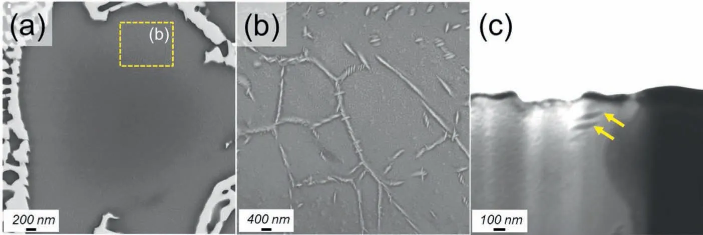
Fig.3.(a,b) BSE images and (c) bright field STEM image of the sand-cast GK140 alloy before the creep tests.
3.2. Compressive properties
Fig.4 presents the compressive yield strength (CYS),ultimate compressive strength (UCS) and compressibility of the sand-cast GK140 alloy at 25,175,200 and 250 °C.Both the CYS and UCS decrease with the increase of temperature,while the value of compressibility increases.The CYS of the sand-cast Mg alloy changed from 246 to 207 MPa with a reduction of about 15 % (from room temperature to 250 °C).It seems that the yield strength of the Mg alloy did not decrease significantly from room temperature to elevated temperatures.The stresses selected in the following compressive creep tests should be much lower than the yield strength at the corresponding temperature.
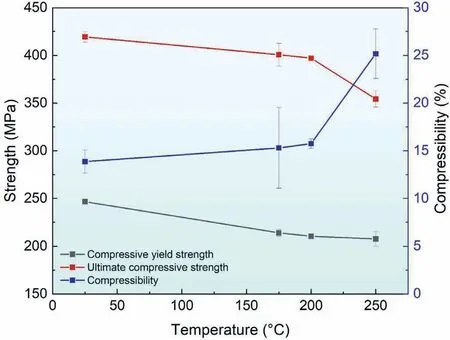
Fig.4.Compressive properties of the sand-cast GK140 alloy at temperatures from room temperature to 250 °C.
3.3. Creep properties
Fig.5a shows the representative creep curves of sand-cast GK140 alloy tested at 250 °C under the applied stresses of 60,80 and 100 MPa.All the creep curves consist of three typical regions,while the sample rupture did not occur until 200 h.Each region has their own distinctive creep strain-time feature.For the primary stage,the creep rate decreases continuously within a rather short period (about 10 h) owing to the occurrence of work hardening.The curves within 10 h are enlarged in the Fig.5b,showing that there exists an instantaneous deformation under all the given applied stresses.Compared to the Mg alloy tested under 60 and 80 MPa,the sample tested under 100 MPa shows the highest creep strain and ends the primary creep stage the earliest (4.5 h).After that,the curve pattern becomes almost linear,indicating that the creep rate reaches to the lowest value and remains barely changed by bringing in the effect of thermal softening.In this secondary stage,the lowest creep rate was calculated from the time derivative of the creep curve,which was considered as the steady creep rate.However,the duration of the secondary stage varies among these three curves under different applied stresses.Under a relatively high stress (such as 100 MPa),the tertiary stage of creep occurs at about 120 h,much earlier than that under 60 and 80 MPa.The corresponding creep data obtained from creep curves in Fig.5a were summarized in Table 2.It is apparent that the creep behaviors of sand-cast GK140 alloy vary under three different applied stresses.The creep strain at 100 h and steady creep rate are raised with the increasing applied stress,demonstrating that the creep resistance is applied stress-dependent at a specific temperature.After comparing with previous results,it is known that the steady creep rate of the sand-cast GK140 alloy is close to that of the hot-rolled Mg–10.5Y alloy [28],but lower than that of extruded Mg–10Gd–3Y–0.5Zr alloy [20]under the same creep condition.

Table 2Creep data of the sand-cast GK140 alloy at 250 °C under different applied stresses.
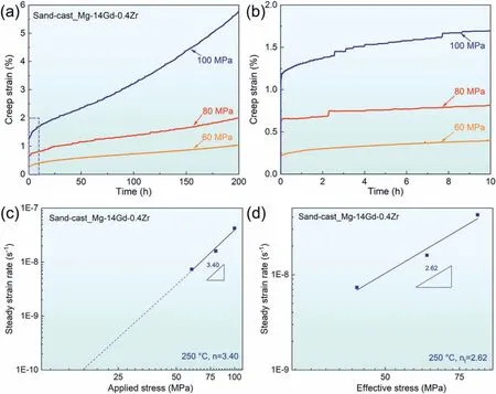
Fig.5.(a) Compressive creep curves under different applied stresses,(b) an enlarged portion of creep for the first 10 h in (a),(c) double-logarithmic plot of steady creep rate versus applied stress,and (d) Lg-lg plot of steady creep rate against effective stress for the sand-cast GK140 alloy crept at 250 °C.
The double logarithmic plot of steady creep rateversus the applied stressσis given in Fig.5c for the sand-cast GK140 alloy,where the curve is fitted to the Norton-Bailey power-law [29]expressed as follows:
whereA,n,Q,RandTare material-dependent coefficient,stress exponent,activation energy of creep,gas constant and the absolute temperature,respectively.The stress exponents can be determined under a fixed temperature (250 °C,in this study) using logarithmic method.Generally,its value is used to predict creep mechanisms of metallic materials.According to the aforementioned equation,the calculated stress exponentnis 3.40 at 250 °C under stresses from 60 to 100 MPa.Considering the present alloy contains lots of second phase particles and such particles interacted with dislocations [30],thus,the threshold stressσthrwas introduced to re-calculate the stress exponent,i.e.the true stress exponent,for evaluating the creep mechanisms.The Eq.(1) can then be modified as below:
where the threshold stressσthrwas calculated using Li and Langdonś model [31]at the intersection of=10-10s-1and the linear regression plot ofwith respect toσ.As plotted in Fig.5c,theσthrvalue was estimated as about 17.2 MPa.
Fig.5d displays the double-logarithmic plot ofversus effective stressσeff,giving an updated value of 2.62 for the true stress exponentnt.Theoretical speculations on creep mechanisms are strongly associated with true stress exponents,as suggested in Refs.[1,30,32-35].Specifically,a value ofn=1 corresponds to diffusion-based creep,n=3 indicates creep controlled by viscous glide of dislocations,n=5 and 7 stand for dislocation climbing at elevated temperatures and low temperatures,respectively.Hence,viscous glide of dislocations is responsible for the compressive creep for the present sandcast GK140 alloy under applied stresses of 60–100 MPa at 250 °C.
3.4. Evolution of precipitates and PFZs during creep
To further gain insights into the compressive creep mechanism,SEM and TEM observations were carried out on the crept sand-cast GK140 alloy,focusing on its microstructural evolution and dislocation configurations during creep.As shown in Fig.5d,the true stress exponent keeps unchanged under the applied stresses 60–100 MPa,indicating that the same creep mechanism dominated during compressive creep.In the present investigation,the specimen crept under 250 °C/80 MPa was selected for microstructural investigation after creep deformation.Its corresponding curve of creep rate depending on the time (Fig.6) clearly illustrates various creep stages.Based on this creep curve,two interesting data points,i.e.two specimens crept for 39 h (early secondary creep stage) and 95 h (mid-late secondary creep stage),were taken to explore how their microstructural evolutions proceeded during creep deformation.
The precipitates existed in the sand-cast Mg alloys after creep for 39 h were characterized in detail (Fig.7).The BSE image in Fig.7a shows that the phase constitution remains unchanged with the coarsening of eutectic phases (α-Mg+Mg5Gd).Fig.7b is the enlarged view of Fig.7a,indicating that there exist some narrow regions without precipitates(denoted by red arrows) in the vicinity of grain boundaries(GBs),hereby referred to as PFZs.Fig.7c-h reveals the types of fine precipitates inside the grains and their morphologies.Observed from the orientation [0001]α,some chain-like precipitates distributed along [100]α,[010]αand [010]αdirections.It seems that suchlike precipitate chains (Fig.7d)comprised two different phases.This speculation was further investigated and confirmed using the high-resolution TEM(HRTEM).According to the fast Fourier transform (FFT) patterns of the HRTEM images (Fig.7e and f),the elliptical precipitate with a big size was identified asβ’ (cbco structure,a=0.64 nm,b=2.22 nm,c=0.52 nm) [15],and its small neighboring precipitate was determined asβ’F(cbco,a=0.689 nm,b=1.088 nm,c=0.517 nm) [36].In addition,the precipitatesβ’ andβ’Fexhibited an alternating distribution,coexisting in these precipitate chains.Another fine plate-like precipitate was recognized asβ1phase (highlighted by white arrows in (Fig.7g),fcc structure,a=0.74 nm)[15](Fig.7h).At the early secondary creep stage (39 h),therefore,β’+β’Fprecipitate chains dominated the grain interiors with a small amount ofβ1precipitates,while some PFZs andβphases distributed along the GBs.

Fig.7.(a) BSE image and (b) its enlarged image of the sand-cast GK140 alloy crept under 250 °C/80 MPa for 39 h;(c,d) HAADF-STEM images showing the morphology of precipitates and (e,f) HRTEM images of typical precipitates,observed along the zone axes of [0001]α;(g) HAADF-STEM image and (h)its corresponding HRTEM image showing the precipitate information viewed along [110]α.
In order to verify the different impacts of these tiny precipitates,their interface relationships with Mg matrix were investigated based on our HRTEM results [37,38].The phase with dark contrast in Fig.8a is confirmed asβ’ precipitate,and its orientation relationship withα-Mg phase is (100)β’//(110)αand [001]β’//[0001]α(Figs.8b and c).Along the direction of<110>α,the lattice mismatch betweenα-Mg andβ’ phase was calculated as 2.1%.The smooth interface can be easily observed and misfit dislocations were barely observed in the interface (Fig.8a),demonstrating that theβ’ precipitate is fully coherent with Mg matrix [38].For the precipitateβ1,however,its interface relationship withα-Mg cannot be clearly distinguished by HRTEM,since limited amounts ofβ1existed in both the sand-cast and peak-aged Mg alloys after creep deformation.Theseβ1precipitates grew even among large amounts ofβ’ phase (Figs.7g and 10h).Therefore,their interfacial relationship is mainly referred to the detailed investigation by Miao et al.[37].The interface ofβ1/α-Mg exhibited a semi-coherent morphology,where the lattice distortions could be found.Given the relatively weak atomic bonding of the semi-coherent or incoherent precipitates [37],cracks are more likely to form during deformation in the samples containingβ1phases instead ofβ’ phase.
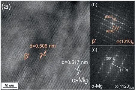
Fig.8.(a)HRTEM image of the interfacial region between precipitate β’and α-Mg,and its corresponding FFT patterns for (b) β’ and (c) α-Mg region.
Fig.9 presents the second phases with a large size in the creep-deformed sand-cast GK140 alloy (interrupted at 95 h).The skeletal phases in Fig.7 changed into small pieces(eutectics in Fig.9a),whose volume fraction decreased from 2.16%to 1.32%.In addition,the grain size of the sand-cast Mg alloy decreased from~52.6 to~41.3 μm with creep time increasing from 39 to 95 h.This could result from recrystallization,aroused by the creep condition(250°C/80 MPa)and the accumulation of dislocations during creep.Several cuboid-shaped phases (marked by red arrows in Fig.9b) were observed near the grain boundaries.The morphology of such phase (Fig.9c)is similar to our previous findings [39],whose corresponding diffraction pattern (Fig.9d) could be well indexed to GdH2phase,a face-centered cubic (fcc) structure with a lattice parametera=0.53 nm [40].The average size of these small amounts of GdH2phases is around 0.8–1.5 μm in Mg alloy crept for 95 h,showing no significant changes in comparison with that crept for 0 and 39 h.The detrimental or beneficial effects evoked by these stable GdH2phases can be neglected due to their limited volume fractions.Moreover,these hydrides did not really exist inside the creep specimens.Our previous investigations demonstrated that they were formed during specimen preparations for microstructural observations[39].Compared to Fig.7(b),the PFZs (highlighted by white arrows) in Fig.9b are more apparently observed.
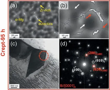
Fig.9.BSE and TEM images of the sand-cast GK140 alloy crept for 95 h at 250 °C under 80 MPa.(a) BSE image,(b) the enlarged BSE image of (a),(c)TEM observation for the cuboid phase with (d) its corresponding SAED pattern observed along [0001]α.
Fig.10 displays the different types of fine precipitates in the crept alloy (95 h) and their morphologies.The magnified HAADF-STEM image in Fig.10b illustrates that another precipitate exists between every two truncated-ellipse shaped precipitates but with no well-defined interface.They were confirmed asβ’F(marked by green in Fig.10d) andβ’ (denoted by light orange in Fig.10c) via HRTEM,and distribute alternately forming the precipitate chain (Fig.10b).This phenomenon occurred at a creep time of 95 h is similar to that at 39 h.As shown in Fig.10a,three morphological variants ofβ’ andβ’Fphases [41]could be observed,while theβ’+β’Fprecipitate chains tended to distribute only with parallel to [100]α.Additionally,a coarsen precipitate with a width of~53 nm locally occurred in the embrace of the clusters ofβ’+β’Fprecipitate chains[15],which was identified as precipitateβ(Fig.10f) with a fcc structure,a=2.23 nm.An area without precipitates was formed around the large platelikeβ-phase since a substantial amount of Gd solute atoms was consumed for the growth of this particle [14].Based on the HRTEM image with its corresponding FFT pattern(Fig.10g),the adjacent precipitate ofβisβ’ phase,indicating that the increase ofβphase gradually expended precipitateβ’ [42].The fine plate-like particleβ1was also figured out in the creep deformed Mg alloy (95 h) (Fig.10h and i).Thus,these coarseningβ’+β’Fprecipitate chains with a limited amount ofβ1andβphases governed the grain interiors in the sand-cast GK140 alloy after creep under 250 °C/80 MPa for 95 h.
Fig.11 demonstrates the key features of PFZs in the sandcast GK140 alloy after creeping for both 39 and 95 h under 250 °C/80 MPa (exhibited in Fig.7b and Fig.9b),including the precipitates inside the grains,the phases at GBs and the width of PFZs [43].The numerous fine precipitates distributed homogeneously within the grain interior,as indicated in Figs.7 and 10.As mentioned above,Mg5Gd(β)phase had a discontinuous distribution at GBs in the sand-cast Mg alloy before creep.With the creep proceeding (39 h),it was easily coarsened and elongated (Figs.11a and c) by consuming the surrounding Gd solute atoms.Thus,the PFZs were produced and even expanded during creep,which in turn verifies the solute depletion mechanism reported in [44].The enhanced diffusion of the Gd solute along grain boundaries [45]but lower diffusivity inα-Mg [46]caused that the strengthening precipitates cannot be formed near the GBs,resulting in the occurrence of PFZs.As aforementioned,however,theβphases became smaller to some extent when the sample tested for 95 h due to recrystallization.The width of PFZs were determined as the distance between the grain boundary and the marked side in Fig.11.The widths of the PFZs in the creep deformed Mg alloys (39 h) observed from [0001]α(Fig.11a) and [110]α(Fig.11b) are nearly identical with about 0.38 μm.This is also the same for Mg alloy after crept for 95 h(Fig.11c and d).The observations from different orientations indicate the widths of PFZs are about 0.58 μm.
4.Discussion
4.1. At the early stage of secondary creep (39h)
According to the calculated true stress exponent (2.62) for the sand-cast GK140 alloy at 250°C,its possible creep mechanism is viscous glide of dislocations.To further uncover the specific dislocation configuration,the crept specimens (interrupted timely during the steady creep stage) were carefully investigated using HAADF-STEM.Fig.12 was taken under two-beam diffraction mode in the same area with three differentg-vectors and incident beam directionB=[110].The invisibility criterion ofg·b=0 was utilized to distinguish the types of dislocations in the hexagonal close-packed (hcp) lattice structure [47],wheregandbrepresent operation vector and Burgers vector of dislocation,respectively.The dislocations herein are invisible in theg=0002 (Fig.12a),while become visible in theg=010 and 011 conditions (Fig.12b and c),demonstrating that they are <a>type dislocations withb=1/3<110>[48].In addition,these dislocations (marked by blue arrow in Fig.12) are all lying on or perpendicular to the (0001) basal plane,which are identified as basal <a>dislocations and prismatic <a>dislocations,respectively.Straight basal <a>dislocations and prismatic <a>dislocations are linked with each other,showing that some <a>dislocations cross from the basal plane to its neighboring prismatic plane [49].

Fig.12.HAADF-STEM images under two-beam conditions with incident beam direction B=[110]for the sand-cast GK140 alloys crept under 250°C/80 MPa for 39 h, g=(a) [0002]α,(b) [010]α and (c) [011]α,respectively.
As shown in Fig.12,most fine precipitates within the grain interiors (mainlyβ’+β’Fprecipitate chains) are distributed perpendicular to the basal plane,effectively arresting the basal <a>dislocations,thus improving the creep resistance.Under such creep condition 250 °C/80 MPa for 39 h,the absence of <c+a>dislocations may be attributed to the small creep strain (1.05%) [50]of sand-cast Mg alloy.Therefore,the cross-slip with basal and prismatic <a>dislocations dominated the creep mechanisms of the sand-cast Mg alloy under creep loading at 250 °C for 39 h.
4.2. At the later stage of secondary creep (95h)
Fig.13 presents the HAADF-STEM images of the sandcast Mg alloys crept under 250 °C/80 MPa for 95 h using the same observation condition in the Section of 4.1.It is found that a mass of long dislocations are parallel to the basal plane when theg-vector was set as 010 or 011 (Figs.13b and c).These dislocations were recognized as basal 〈a〉 dislocations.Additionally,a few curve dislocation lines perpendicular to the basal plane are also visible under such twog-vectors(Fig.13b and c)but invisible underg=0002(Fig.13a).They are suggested to be prismatic 〈a〉 dislocations connected by basal <a>dislocations.Compared to Fig.12,the <a>dislocations (marked by blue arrows in Fig.13) are much longer.Perhaps the reason is that the decomposition of metastableβ’+β’Fprecipitate chains gave more space for the movement of dislocations,leading to an increment of creep strain.

Fig.13.Dislocation configurations of the sand-cast GK140 alloy crept under 250 °C/80 MPa for 95 h.HAADF-STEM images with g=(a) [0002]α,(b)[010]α and (c) [011]α.
<c+a>type dislocations withb=1/3<113>[51]were also activated in the sand-cast Mg alloy under the creep loading for 95 h (marked by red arrows),which are all visible under all aforementioned diffraction vectors.Pyramidal<c+a>dislocations are normally considered to have an effective influence on the creep resistance of Mg alloys for their contributions to strain hardening [52].Current TEM observations indicated that masses of dislocations (both <a>dislocations and <c+a>dislocations) tend to distribute near the GBs,rather than are hampered by the fine precipitates within the grain interiors (Fig.13).Based on the results in Fig.11,it could be concluded that the widening of PFZs was attributed to such distribution of dislocations.The dislocations are easy to be activated and move or pile up or accumulate in these precipitate-free areas due to their low-strength without precipitate strengthening.Therefore,at the later stage of secondary creep the main creep mechanism of the sand-cast GK140 alloy became cross-slip of basal and prismatic 〈a〉 dislocations as well as the pyramidal <c+a>slip.
4.3. Possible evolution mechanisms for Mg–Gd–Zr based alloys
Several microstructural changes during the steady creep stage can be summarized,including the formation and widening of PFZs,dynamic precipitation and dislocation accumulation.The width of PFZs increased gradually when the creep time changed from 39 h to 95 h(Fig.11),resulting in weakening the regions around GBs and the deterioration of creep resistance.PFZs may further decorate the GBs or even the grain tripe junctions,forming the detrimental cracks.Theβ’+β’Fprecipitate chains with a triangular arrangement formed the discontinuous networks in the grain interiors of sand-cast alloy crept to 39 h (Fig.7c),which are normally treated as the main strengthening phases to pin basal dislocations,thus enhancing its creep resistance.Compared to singleβ’ type precipitates,interestingly,the alternative distribution ofβ’andβ’Fprecipitates could efficiently reduce the magnitudes of the tensile and compressive stresses in and around theβ’ phase[36].Nonetheless,some of the metastableβ’+β’Fprecipitates chains andβ1phase (at 39 h) coarsened or dissolved to large plate-like stableβprecipitates(95 h,Fig.10e).Different from the coherent precipitatesβ’ andβ’F[53],the semi-coherentβ1phase and incoherentβphase are relatively stable[54]and exhibit weaker strengthening effects.The weak strengthening effect ofβphases and their adjacent precipitate-free regions (Fig.10e) further deteriorate the creep performance of the sand-cast Mg alloy.Meanwhile,with the creep proceeding,the coarsenedβ’+β’Fprecipitate chains changed into the lamella shape with growing in a preferential direction (95 h,Figs.10a and e).Theβ’ precipitate gradually governed the alternating distributed precipitate chains,along with the decrease of the linkingβ’Fprecipitates.The schematic diagram is roughly depicted in Fig.14.Such morphological characteristic is not so strong as the discontinuous network structures (39 h).Consequently,such microstructural evolution of precipitates during creep deformation also reduce the creep resistance of sand-cast GK140 alloy.
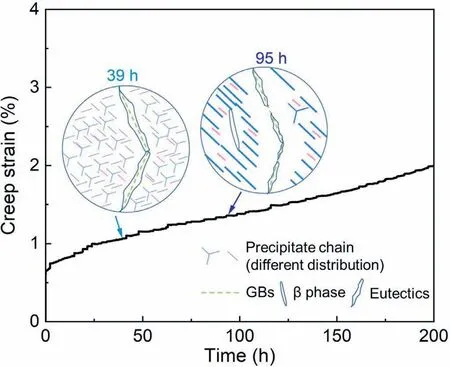
Fig.14.Schematic diagram of main precipitates and PFZs evolution in the sand-cast GK140 alloy under 250 °C/80 MPa.
During creep deformation,β’+β’Fprecipitate chains hindered the dislocations movement of the sand-cast Mg alloy and improved the creep property with Orowan mechanism[55].It is widely accepted that the finer precipitates,the higher Orowan stress.Furthermore,the creep threshold stress is proportional to the Orowan stress,which represents the external stress required to start the creep.Therefore,masses of fine precipitate chains are expected to reduce the creep rate of the Mg–Gd–Zr based alloys.
The cross-slip including the basal and prismatic <a>dislocations is the main creep mechanism for the sand-cast GK140 alloy crept for 39 h under 250 °C/80 MPa (Fig.12).The prismatic precipitate chains inside the grain effectively obstructed the dislocations,resulting in the reduction of creep rate of Mg alloys.With the creep time increasing,the<c+a>dislocations are activated,while〈a〉dislocation lines tend to be longer,and a large amount of dislocations gathered near GBs (Fig.13).Then the creep strain are accumulated and the creep performance of the sand-cast GK140 alloy is impaired.
5.Conclusions
Precipitation behavior,PFZs evolution and dislocation configurations of the sand-cast GK140 alloy,as well as its hightemperature compressive creep resistance at 250 °C were investigated.The following conclusions can be reached:
(1) The threshold stress originated from precipitation hardening is introduced for calculating the true stress exponent,whereσthrandntare determined as 17.21 MPa and 2.62,respectively.The movement of dislocations is suggested to be the main creep mechanism of the sandcast GK140 alloy at 250 °C under the given applied stresses.
(2) During the secondary creep stage,alternating distributedβ’+β’Fprecipitate chains effectively improve the creep resistance.With the creep proceeding,precipitatesβ’andβ’Fcoarsen and transform toβ1phase,even followed by the precipitation of large plate-likeβprecipitates.Besides,the width of PFZs near grain boundaries becomes larger.Semi-coherentβ1phase,incoherentβphase along with its surrounding precipitate-free areas and the widening PFZs deteriorate the creep resistance and cause the further increment of the creep strain.
(3) At the early steady creep stage (interrupted at 39 h),the creep deformation is mainly controlled by the cross-slip of basal and prismatic <a>dislocations.At the later steady creep stage (after 95 h) <c+a>dislocations occur,promoting the increase of creep strain.
Declaration of Competing Interest
The authors declare that they have no known competing financial interests or personal relationships that could have appeared to influence the work reported in this paper.
Acknowledgments
Thanks to the Shanghai Sailing Program (23YF1417100),National Natural Science Foundation of China(U2037601),as well as China Scholarship Council(Grant No:202006890008)for the financial support.Hui Shi wishes to thank the meaningful discussions on TEM characterizations and analyses with Dr.Chong Lu and Dr.Chunquan Liu,on OM and SEM characterizations with Dr.Sarkis Gavras,Mr.Gert Wiese and Ms.Petra Fischer,on XRD tests with Dr.Maria Serdechnova,as well as on composition test with Mr.Daniel Strerath in this study.
 Journal of Magnesium and Alloys2023年9期
- Journal of Magnesium and Alloys的其它文章
- Corrosion behavior of composite coatings containing hydroxyapatite particles on Mg alloys by plasma electrolytic oxidation: A review
- Rational design,synthesis and prospect of biodegradable magnesium alloy vascular stents
- Antibacterial mechanism with consequent cytotoxicity of different reinforcements in biodegradable magnesium and zinc alloys: A review
- Preparation,interfacial regulation and strengthening of Mg/Al bimetal fabricated by compound casting: A review
- Pitting corrosion behavior and corrosion protection performance of cold sprayed double layered noble barrier coating on magnesium-based alloy in chloride containing solutions
- Designing strategy for corrosion-resistant Mg alloys based on film-free and film-covered models
