An innovative joint interface design for reducing intermetallic compounds and improving joint strength of thick plate friction stir welded Al/Mg joints
Yng Xu ,Liming Ke ,Yuqing Mo ,Jifeng Sun ,Yxiong Dun ,Limin Yu
a National Defence Key Discipline Laboratory of Light Alloy Processing Science and Technology, Nanchang Hangkong University, Nanchang 330063, PR China
b State Key Laboratory of Solidification Processing, Northwestern Polytechnical University, Xi’an 710072, PR China
Abstract Friction stir welding of dissimilar Al/Mg thick plates still faces severe challenges,such as poor formability,formation of thick intermetallic compounds,and low joint strength.In this work,two joint configurations,namely inclined butt (conventional butt) and serrated interlocking(innovative butt),are proposed for improving weld formation and joint quality.The results show that a continuous and straight intermetallic compound layer appears at the Mg side interface in conventional butt joint,and the maximum average thickness reaches about 60.1 μm.Additionally,the Mg side interface also partially melts,forming a eutectic structure composed of Mg solid solution and Al12Mg17 phase.For the innovative butt joint,the Mg side interface presents the curved interlocking feature,and intermetallic compounds can be reduced to less than 10 μm.The joint strength of innovative butt joint is more than three times that of conventional butt joint.This is due to the interlocking effect and thin intermetallic compounds in the innovative joint.
Keywords: Al/Mg joint;Friction stir welding;Thick plate;Intermetallic compounds;Joint strength.
1.Introduction
Aluminum (Al) and magnesium (Mg) are both the lightest structural metals with high specific strength,which are very attractive for automobile,high-speed rail and aerospace[1,2].The Al/Mg hybrid structure could further reduce weight and utilize their respective performance advantages.In order to obtain the Al/Mg joints,conventional fusion welding was adopted by some scholars [3,4].However,massive brittle intermetallic compounds (IMCs),pores and cracks are found at the fusion welded Al/Mg joints due to the high welding temperature.Friction stir welding (FSW),as a solid-state joining method,could overcome many problems caused by the aforementioned fusion welding [5–7].Therefore,FSW has been widely used for obtaining the reliable Al/Mg joint [8–12].For instance,Kwon et al.reported that 2 mm thick FSWed Al/Mg joints displayed a tensile strength of 132 MPa [8].
However,as the thickness of base metals (BMs) is over 10 mm,then the mechanical properties of the Al/Mg joints became extremely poor.It was reported that the tensile strength of Al/Mg joint with 10 mm thickness was only 20.62 MPa[13].When the thickness of BMs (Al and Mg) increased to 12 mm,the welded joints cracked under preparation of metallographic sample [14].Beside,Xu et al.observed that there was more serious microstructural inhomogeneity (such as IMCs) along thickness direction of the thick plate [15,16].These IMCs usually precipitated along the entire interface,and their thickness were thicker than that of the thin joints less than 6 mm [17].Therefore,the thick plate Al/Mg joint easily fractures at the interface and does not exhibit any ductility.Currently,there is still no progress in improving the joint strength of thick plate Al/Mg FSW joints.
In order to reduce the formation of brittle IMCs,some efforts were used into the Al/Mg joints.Abdollahzadeh et al.employed 0.3 mm thick Zn interlayer in 5 mm thick butt joint of 6061Al to AZ31 Mg [18].But,many Al-Mg IMCs with banded structure existed at the stir zone.Moreover,the submerged FSW was proposed for decreasing the thermal history.The various coolants,including water [19–22]and liquid nitrogen[23],were adopted in thin Al/Mg joints.These coolants could merely reduce the peak temperature near the surface of the sample,and have no obvious cooling effect on the internal stir zone.Recently,the ultrasonic vibration has been used as an auxiliary energy in Al/Mg FSW [24,25].The brittle and hard IMCs still existed at the Al/Mg interface,and the amount of the IMCs had not been reduced during ultrasonic vibration enhanced FSW [20].
Furthermore,the formation of IMCs was actually dominated by metallurgical reaction,which was related to the local composition[26],reaction temperature[27]and strain rate[28,29].Therefore,as long as these three reaction conditions are controlled,the thickness of IMCs can be theoretically suppressed.For the Al/Mg FSW,as the reaction interface is farther away from the pin,its peak temperature and plastic deformation significantly decrease,which provides a new idea for inhibiting IMCs thickness.Based on the above analysis,in this research,two types of joint configurations were innovatively designed to inhibit the IMCs thickness of 15 mm thick Al/Mg FSW joints.One was the inclined butt joint,the purpose of which was to control the relative content of Al and Mg.The other was to set interlocking structure on the basis of the inclined butt joint,and further reduce the reaction temperature and strain rate.
2.Materials and method
The 5A06-H112 Al alloy and AZ31B-O Mg alloy plates were butt welded by FSW Table 1.listed their nominal chemical compositions of the BMs.The original length,width and thickness of the BMs were 150 mm,90 mm and 15 mm,respectively.A shoulder with three grooves and conical pin with thread were prepared for FSW.The diameter of shoulder,pin root and pin tip were 40 mm,14 mm and 8 mm,respectively.The pin length was 14.7 mm in this experiment.To control the relative content of Al and Mg in stir zone along the thickness direction,an inclined butt joint without interlock (conventional joint) was designed,as presented in Fig.1a.The inclined faying surface was parallel to the outer edge of the pin.As an improved case,Fig.1b,c presented the serrated interlocking configuration (innovative joint) and its specific size.The height a of the first groove from the upper surface depended on the size of the shoulder affected zone(SAZ).In this experiment,the value of H1was 4 mm.The width (w and w)´ of the interlocking groove was less than or equal to the range of the thermo-mechanically affected zone(TMAZ),which was to ensure that Al and Mg can form a metallurgical reaction under certain temperature and plastic deformation.After repeated experimental measurements,the w and were about 4 mm and 12 mm,respectively.The distance H2between the first groove and the second groove was set as 4 mm,which could maintain the stability of the interlocking structure when the pin passed this groove.Meanwhile,in order to reduce the content of Mg in the stir zone,the height h1of the first groove and second groove was taken as 2 mm.It was worth noting that the lock structure at the bottom of the BMs was to solve the incomplete penetration.The Al alloy and Mg alloy were positioned at the advancing side (AS) and retreating side (RS),respectively.The above two cases both applied an offset of 1 mm to the Mg side (doff=1 mm),as shown in Fig.1a and c.The rotational speed of 375 rpm and welding speed of 23.5 mm/min were adopted according to the preliminary experiment [16].

Fig.1.Schematic illustration of different joint configuration: (a) conventional joint;(b,c) innovative joint;(d) Al/Mg FSW process.

Table 1The nominal composition of AZ31B Mg and 5A06 Al (wt.%).
The microstructure and elemental content of Al/Mg FSW joint was observed by 4XB-TV optical microscopy(OM),and SU1510 scanning electron microscopy (SEM) equipped with energy dispersive X-ray spectroscopy (EDS).The interfacial IMCs at the Mg side was further analyzed by FEI-TabsF200X transmission electron microscopy (TEM).The TEM samples were prepared by using focused ion beam (FIB,FEI Helios NanoLab 600i).The tensile test of the Al/Mg joints were conducted at a displacement of 0.05 mm/min by a universal testing machine.The size of tensile sample was presented in Fig.2,which corresponded to the E8 M11 standard.

Fig.2.The dimension schematic of tensile sample.
3.Results
3.1. Macrostructure of the Al/Mg joints
Fig.3 shows the cross-sectional morphologies of Al/Mg FSW joints fabricated under conventional and innovative joints.It is observed from Fig.3a,b that there is no obvious defect in the Al/Mg joints.As shown in Fig.3b,the conventional joint performs “gourd” shape,which is narrow in the upper but wide in the lower.Additionally,the interface near the Mg side exhibits a continuous line,as indicated by yellow dotted line.The area of the mixed zone for the conventional joint is about 118.6 mm2by Image J software.Different from the conventional butt,the cross-sectional morphology obtained by innovative butt presents “bottle” shape,and the width along the thickness direction is relatively consistent,as presented in Fig.3b.It is also seen from Fig.3b that the Mg side interface performs a zigzag shape rather than a linear.This result is directly related to the adoption of the interlock in Fig.1b.The area of the mixed zone at innovative joint is approximately 125.6 mm2.

Fig.3.Macrostructure of the Al/Mg joints obtained by two joint configurations: (a) conventional joint;(b) innovative joint.
3.2. Interfacial microstructure of the Al/Mg joints
The interfacial microstructures near the Mg side obtained by the conventional joint are depicted in Fig.4.Fig.4a1,a3 and a4 show the OM microstructures of the upper,middle,and lower,respectively.The OM microstructure located between the upper and middle is shown in Fig.4a2.Moreover,the enlarged SEM images positioned at Fig.4a1–a4 are also shown in Fig.4.As seen from Fig.4al and b1,a~60.1 μm thick IMCs layer with two sublayers is distributed along the Mg side interface.Two sublayers are further identified by EDS (Table S1) as Al3Mg2and Al12Mg17,respectively,as indicated by area 1 and area 2 in Fig.4b1.It is seen from Fig.4a2 and b2 that a thick layered structure with~184.1 μm thickness forms between the upper and middle.This layered structure contains 63.12 at.% Mg and 36.88 at.% Al according to the EDS at the area 3.Combined with the Al-Mg binary phase diagram,this layered structure is local melting area,which is consisted of Mg solid solution and Al12Mg17phase.This result confirms that the eutectic reaction (Mg+Al12Mg17↔L) has occurred during the thick plate Al/Mg joints.Xu et al [15].also reported that the peak temperature near the middle of Mg side interface had exceeded 437 °C,which easily induced the eutectic reaction.In the middle of the Mg side interface,a continuous IMCs layer with 20.3 μm thickness is observed at this location.The SEM and EDS in Fig.4a3 and b3 show that there are two sublayers,namely Al3Mg2and Al12Mg17.The narrower IMCs layer with 9.4 μm forms at the lower,as shown in Fig.4b4.It is concluded from Fig.4 that the Mg side interface has a reliable metallurgical bonding due to the formation of continuous IMCs layer.But these IMCs are straightly distributed on the Mg side interface,which may not be conductive to the improvement of joint strength of Al/Mg joint compared with curved interface[30].
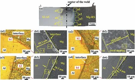
Fig.4.Interfacial microstructures along the thickness direction of the Mg side obtained by using the conventional joint: (a) cross-sectional morphology of Al/Mg joint;(a1–a4) interfacial microstructures corresponding to different positions marked as “a1–a4” in Fig.4a.
The Al side interfacial microstructures along the thickness direction using conventional joint are shown in Fig.5.To judge phase composition near the interface,the EDS result is presented in Table S2.It is found that the upper of this interface exists two kinds of IMCs,which are identified as Al3Mg2and Al12Mg17,marked as red arrow in Fig.5a.These IMCs near the interface exhibit irregular dendritic feature,indicating that the IMCs has melted and solidified.It was reported that the peak temperature near the Al side interface has reached 442.5 °C,which has exceeded the melting point of the Al12Mg17phase [16].This report is consistent with dendritic IMCs observed in this experiment.At the middle of this interface,large sized Al3Mg2phase forms,as presented in Fig.5b.Some fine recrystallized grains are found near the lower of the interface due to the severe plastic deformation(SPD).These grains contain 89.88 at.% Al and 10.12 at.%Mg,respectively,which exceeds the concentration of Mg in Al at the original Al matrix.This is attributed to the fact that SPD enhances the diffusion of Mg atoms into Al [31].

Fig.5.Interfacial microstructures along the thickness direction of the Al side obtained by using the conventional joint: (a–c) interfacial microstructures corresponding to different positions marked as “a5–a7” in Fig.4a (For interpretation of the references to color in this figure,the reader is referred to the web version of this article.).
For comparison,the interfacial microstructures near the Mg side prepared by innovative joint are shown in Fig.6.A thin IMC layer with thickness of~7.5 μm emerges at the upper of this interface,as presented in Fig.6a1-b1.This thickness is much thinner than that of the conventional joint at the same position Fig.6a2–b2 exhibits the interfacial morphology between the upper and middle.As seen from Fig.6b2,the thickness of IMCs layer is only 4.9 μm,which is also much thinner than that of the conventional joint at the same position.In the middle of the interface,the Mg and the Al penetrate each other to form an interlocking interface with metallurgical bonding,as indicated by yellow arrow in Fig.6a3–b3.This shows that the designed serrated joint can realize interface interlocking.Fu et al.reported that mutual penetration of Al and Mg could enhance the interfacial joint strength [30].The next section further compares the effect of the interlocked butt and conventional butt on the joint strength.Additionally,Fig.6a4 shows the locking interface at the root of the Mg side.The IMCs layer with 6.8 μm thickness exists at the locking interface.The above results show that the Mg side prepared by innovative butt can significantly reduce the thickness of the IMCs.However,the internal information (thickness and element distribution) of IMCs layer is impossible to obtain by SEM-EDS due to very thin IMCs layer.Therefore,the interfacial TEM sample marked as white rectangle in Fig.6b1 is made by FIB.
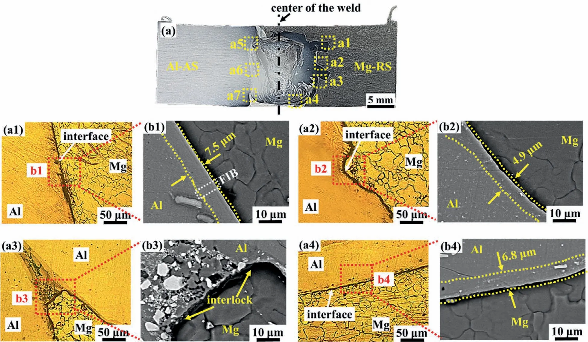
Fig.6.Interfacial microstructures along the thickness direction of the Mg side obtained by using the innovative butt: (a) cross-sectional morphology of Al/Mg joint;(a1–a4) interfacial microstructures corresponding to different positions marked as “a1–a4” in Fig.6a.
Fig.7 displays the bright field image,EDS map and SAED pattern at the white box in Fig.6b1.It is observed from Fig.7a that two sublayers of IMCs have an average thickness of 6.2 μm and 2.6 μm,respectively,which are distributed between Al and Mg.The EDS maps clearly show that the Mg and the Al have diffused towards each other,as shown in Fig.7b–d.The IMCs sublayer near the Al side contains the 58.62 at.% Al and 41.38 at.% Mg (see Fig.S1),respectively,which can be inferred to be the Al3Mg2phase.On the other side,the Al content of the IMCs sublayer is reduced to 42.76 at.%,and the Mg content is increased to 57.24 at.%(see Fig.S1).This sublayer can be judged as Al12Mg17phase.Furthermore,two SAED patterns marked as number 1 and 2 in Fig.7a are identified as Al3Mg2and Al12Mg17,respectively,as presented in Fig.7e,f.
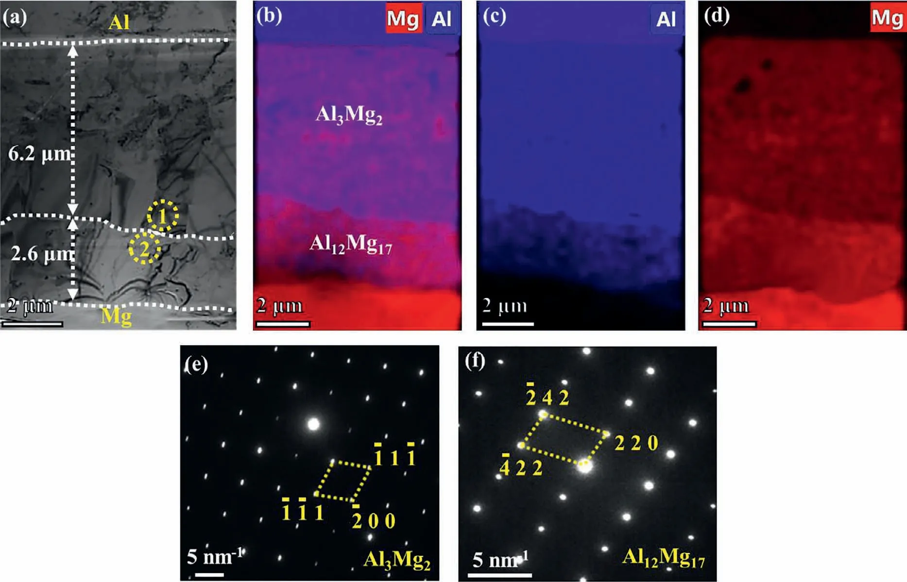
Fig.7.(a) Bright field image corresponding to the area marked as white box in Fig.6b1;(b–d) EDS maps of Al and Mg;(e) SAED pattern of Al3Mg2 phase marked as number 1;(f) SAED pattern of Al12Mg17 phase marked as number 2.
The Al side interfacial microstructures along the thickness direction for innovative joint are exhibited in Fig.8.The EDS results in Fig.8 are presented in Table S3.As seen from Fig.8a,the crack is observed at the stir zone near the upper of Al side interface.The magnified image of the red rectangle in Fig.8a shows that two continuous transition layer forms at the upper,marked as 1 and 2,respectively.The EDS result indicates that two layers are Al3Mg2and Al12Mg17,respectively.The stir zone near the upper interface is identified as Al12Mg17phase by EDS (Table S3).These Al12Mg17phases present fine dendritic feature,which are caused by the melting of the Al12Mg17phase due to high temperature in the stir zone.The similar phenomenon was also confirmed by Shi et al.[32].It is worth noting that the aforementioned crack passes through these Al12Mg17phases.It can be inferred that the formation of crack may be due to the heat stress induced by the fast cooling in the FSW.
It is seen from Fig.8b and c that the interfaces of the middle and the lower display a good metallurgical bonding.But the stir zone near the middle interface appears some microholes,which are located around theα-Al,as shown in Fig.8b.This may be due to the high temperature in the stirring zone exceeding the melting temperature of the Al3Mg2and Al12Mg17,which are formed during the cooling process after welding [33].The existence of these holes results in stress concentration and crack initiation under the tensile stress.
3.3. Tensile strength and fracture behavior of the Al/Mg joints
Fig.9 presents the stress-strain curves of conventional joint and innovative joint.It can be seen from Fig.9 that the maximum tensile strength of the conventional joint is only 9.2 MPa.The low strength of conventional joint is due to the thick and straight IMCs,which has been exhibited in Fig.4.These thick and straight IMCs are inherently brittle,resulting in worse mechanical interlocking at the Mg side interface [34,35].Through adopting innovative joint,the highest strength can reach to 32.8 MPa,which is more than three times that of conventional joint.This is attributed to the thinner IMCs and stronger interlocking effect.In fact,thick plate Al/Mg joint is difficult to form well because of uneven microstructure (such as IMCs and eutectics) along thickness direction,let alone has high joint strength.For instance,it was reported that a~12 mm thick Al/Mg joint cracked under the relatively light forces experienced during polishing [14].Although good formation of thick plate Al/Mg joints is obtained in this work,the tensile strength is not high compared with that of the sheet [9,36].Hence,improving the tensile strength of thick plate Al/Mg joint is still an extremely challenging problem.
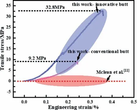
Fig.9.Stress-strain curves of conventional joint and innovative joint.
Fig.S2 shows the fracture locations of conventional and innovative joints.It is seen from Fig.S2 that two joints have different fracture locations,namely the Mg side interface and the stir zone near the Al side interface Fig.10.shows the fracture morphologies of conventional joint and innovative joint.It can be seen from Fig.10a–c that the fracture surface along thickness direction exhibits cleavage-like feature,which indicates that the conventional joints fail through brittle fracture.The fracture morphologies at the upper and lower are smooth,and brittle Al3Mg2phases are also observed on these locations.Some granular Al12Mg17phases fall off from the eutectic structure and gathered at the middle (see red dotted line in Fig.10b),which is consistent with interfacial microstructure near the Mg side (see Fig.4a2–b2) Fig.10d–f present different fracture appearance of innovative joints along the thickness direction.For the upper,fracture surface also shows the cleavage-type brittle fracture.However,two sublayers clearly appear in the middle,one of which is composed of Al3Mg2phase with smooth fracture,and the other is Al solid solution with different depths.At the lower,the fracture surface consists of the Al solid solution.The magnified fracture morphology in Fig.10f shows that some micro-voids intersperse in the Al solid solution.This indicates that the ductile and brittle fracture mode occurs at the innovative joints.

Fig.10.Fracture morphologies of conventional joint and innovative joint: (a–c) represent the upper,middle and lower of the conventional joint,respectively;(d–f) represent the upper,middle and lower of the innovative joint,respectively (For interpretation of the references to color in this figure,the reader is referred to the web version of this article.).
4.Discussion
4.1. Bonding mechanism of Al/Mg interface
Since the pin does not directly touch the Mg when using the innovative joint,the bonding process of Al/Mg joint is different from that of the conventional butt.To clearly show the bonding mechanism of this innovative butt joint,the formation process is present in Fig.11.Firstly,the oxide films between the Al side and Mg side are broken under the huge squeezing force generated by the pin.Then the SPDed Al alloy hits the Mg alloy in a short time,causing diffusion between Al and Mg,as displayed in Fig.11a–b.The Al12Mg17phase nucleates near the Mg side due to its lower Gibbs energy [26].When the Mg atoms continue to move towards Al side,the Al3Mg2phase begins to nucleate.Finally,the Al12Mg17and Al3Mg2grow at the combined effect of high temperature and SPD,as shown in Fig.11c.

Fig.11.Schematic diagram of interfacial bonding mechanism: (a) before FSW;(b) during FSW;(c) end of FSW.
4.2. Effect of interlock on the joint strength
For the dissimilar joint,the IMCs and mechanical interlocking are two kinds of mechanism,which influenced the joint strength [37].This section focuses on the interlocking effect,and the effect of the IMCs on this strength is discussed in detail in the nextSection 4.3Fig.12.shows schematic of the interface length under two kinds of joint configuration.Under the same thickness (T) of BMs,the interface length(L) is calculated by following formula.
Where Lc and Li are interface lengths of conventional joint and innovative joint,respectively;w and w'are the mutual penetration distance of Al and Mg,respectively;andαis angle of inclined butt.In this study,the T is 15 mm,αis 78.5°,w is 4 mm,and w'is 12 mm.By substituting these values,the Lc and Li are approximately 15.3 mm and 39.3 mm,respectively.It can be concluded that the interface length under the innovative joint is much larger than that of the conventional joint.In the case of same BMs,the effective load bearing area increases with the raise of interface length,which is beneficial to improve the joint strength of the Al/Mg joints.Additionally,it is considered that the mutual penetration between Al and Mg provides interlocking effect across the Al/Mg interface [35].
4.3. Effect of interlock on the IMCs thickness
As mentioned in the previousSection 4.1,the diffusion between Al and Mg governs the formation of IMCs.Therefore,the IMCs thickness (d) conforms to the diffusion law,which is expressed as following equations [38,39]:
Wheredis the IMCs thickness,tis the thermal diffusion time,Kis the diffusion coefficient,K0is a frequency factor,Qis the activation energy,Rrepresents the gas constant,andTis the absolute temperature.Liu et al [40].have calculatedK0andQof Al3Mg2and Al12Mg17,as shown in Table 2.

Table 2Activation energies and frequency factors determined for Al3Mg2 and Al12Mg17 in the Al-Mg diffusion couple.
Here,the microstructure of the upper Mg side interface of two joint configurations is discussed as an example.The thermal diffusion time (t) of this interface can be considered as equivalent to the distance passed by the pin [41].In this experiment,the pin diameter at the upper interface and welding speed of the pin were 12.8 mm and 23.5 mm/min,respectively.The thermal diffusion time is about 32.6 s by substituting the pin diameter and welding speed Fig.13.presents the temperature distribution and distance between the interface and centerline of the weld.The number simulation model of temperature field is given in Fig.S3.It can be observed from Fig.13a that the temperature decreases as the distance from the weld centerline increases at the same thickness direction.Specifically,this distance for conventional joint is smaller than that of the innovative joint,as shown in Fig.13b,c.Therefore,it is known from Fig.13a that the reaction temperatures of the upper Mg side interface for conventional joint and innovative joint are 693 K and 682 K,respectively.According to (1.3) and (1.4),the IMCs thickness of conventional joint and innovative joint is calculated as 7.4 μm and 6.8 μm,respectively.This calculated result is obviously different from the actual measurement.
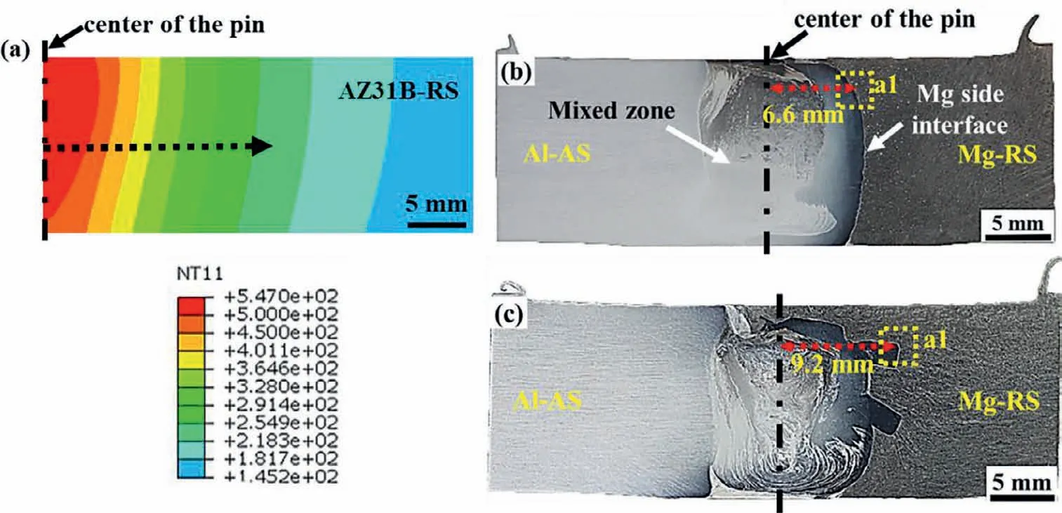
Fig.13.(a) Temperature field of thick plate Al/Mg joint at the 375 rpm and 23.5 mm/min;(b,c) the distance between reaction interface and centerline of the weld,respectively (For interpretation of the references to color in this figure,the reader is referred to the web version of this article.).
In addition to the interface temperature,the strain rate is also a crucial factor affecting the thickness of IMCs [42].The material near the Mg side interface has undergone the SPD at a high strain rate.For the conventional joint and innovative joint,the respective strain rate can be evaluated by (1.5) [43],
whereεandtare the strain and the time required for the pin to travel a distanceRp,respectively.TheRprepresents the radius of the pin.Then,the relationship betweentandwis as follows [44]:
wherewis the rotation speed of the stir tool.Hoyos et al[44].proposed the strain during the FSW as (1.7),
wherehis the width of the TMAZ (mm).The strain rate•εcan be expressed as (1.8),
In this experiment,the effectiveRpat the upper interface and rotational speedware 6.4 mm and 375 rpm,respectively.Combining with the above-mentioned joint microstructure,thehof the conventional joint and innovative joint are 0.21 mm and 2.81 mm,respectively.By substituting these values into(1.8),the strain rates of the conventional joint and innovative joint are calculated as 25.8 s-1and 10.7 s-1,respectively.It can be found that the strain rate of the innovative joint is significantly lower than that of the conventional joint.
During the Al/Mg FSW,a great quantity of vacancies and dislocations is induced by the SPD.These vacancies and dislocations are closely related to the inter-diffusion of atoms[45,46].The high deformation can result into higher diffusion vacancy and dislocations,and finally accelerates diffusion rate at the Al/Mg interface [29].For the innovative joint,the reaction interface at the same thickness is far from the weld centerline (as indicated by red arrow in Fig.13b,c),which causes a relatively low concentration of vacancies and dislocations at this interface due to low strain rate,thereby reducing the diffusion rate between the Al atoms and Mg atoms.
5.Conclusions
Thick plate Al/Mg joints at two configurations were successfully fabricated by FSW.The interfacial microstructure and joint strength of Al/Mg joints were investigated in detail.The following conclusions are drawn:
(1) The IMCs thickness of the innovative joint was thinner than that of the conventional joint.This difference was attributed to the lower temperature and lower strain rate at the Al/Mg interface of innovative joint.
(2) The innovative joint was with interlocking feature,which provided longer interface length and carried greater tensile load.For the conventional joint,the continuous and straight interface was not conducive to better joint strength.
(3) Controlling the uniform and thin IMCs along thickness direction becomes a method to improve the tensile strength of thick plate Al/Mg joint.
Data availability
The raw/processed data required to reproduce these findings cannot be shared at this time as the data also forms part of an ongoing study.
Acknowledgments
This work was supported by the National Natural Science Foundation of China (No.51874179,52005240 and 52164045) and the Young Talent Program of Major Disciplines of Academic and Technical Leaders in Jiangxi Province(No.20212BCJ23028).
 Journal of Magnesium and Alloys2023年9期
- Journal of Magnesium and Alloys的其它文章
- Corrosion behavior of composite coatings containing hydroxyapatite particles on Mg alloys by plasma electrolytic oxidation: A review
- Rational design,synthesis and prospect of biodegradable magnesium alloy vascular stents
- Antibacterial mechanism with consequent cytotoxicity of different reinforcements in biodegradable magnesium and zinc alloys: A review
- Preparation,interfacial regulation and strengthening of Mg/Al bimetal fabricated by compound casting: A review
- Pitting corrosion behavior and corrosion protection performance of cold sprayed double layered noble barrier coating on magnesium-based alloy in chloride containing solutions
- Designing strategy for corrosion-resistant Mg alloys based on film-free and film-covered models
