A Numerical Study of Wave-Structure Interactions for a Square Structure with Different Submerged Depths
-,,-,,
(1.General Research Institute,China National Offshore Oil Corporation,Beijing 100028,China;2.School of Naval Architecture and Ocean Engineering,Jiangsu University of Science and Technology,Zhenjiang 212003,China)
Abstract: The wave-structure interactions for a square structure with different submerged depths are studied numerically by solving URANS equations together with the k-ω SST turbulence model.The present numerical model is validated firstly by carrying out a series of simulation cases for a partiallysubmerged circular structure.It is proved that the present numerical model is able to simulate the hydrodynamic performances of the structures in waves reasonably well by comparing the present numerical results with the published experimental data.There are five simulation cases in which the submerged depth of the square structure varies from -1D to 0.9D in the present study with focus on the vertical wave force,and the free surface elevations and vorticity in the vicinity of the square structure.The results demonstrate that the submerged depth of the structure plays an important role in its hydrodynamic behaviors and that a larger wave impact force occurs in a very short time when the structure is located over the still water level.
Key words:wave-structure interaction;URANS;k-ω SST;free surface elevation;wave force;vorticity
0 Introduction
In the past few decades, the marine operations have become more frequent due to the human beings' marine exploitation activities.The wave-structure interaction in the process of the marine operations is significant, because it determines whether the operations succeed or not.Thus, many scholars and professionals have paid more attention to the relevant researches of the wave-structure interactions.
Li and Lin (2001)[1]conducted a numerical study to investigate the interactions between wave and a square cylinder.The large eddy simulation method was employed to model the turbulent condition of the flow field and the drag coefficients were computed.The numerical results showed the drag coefficient is proportional to 1/KCwhen the wavelength is much longer than the dimension of the structure.However, the drag coefficient decreases dramatically when the wavelength is close to the structure's dimension.Koo and Kim (2007)[2]studied the wave-body interactions for single and double square bodies fixed at the still water level by employing a fully nonlinear potential theory.MEL free surface treatment and Runge-Kutta fourth-order time integration with smoothing scheme was used.The numerical model was validated by comparing the numerical results of the single square body with the published experimental and numerical results.For the double square bodies,the gap distance between the double bodies played an important role in the first-order force, while it could hardly affect the second-and third-order forces.Li and Lin(2010)[3]numerically investigated the nonlinear wave-body interactions for a stationary surface-piercing body with flat and sloping bottoms by solving the spatially-averaged Navier-Stokes equations.Thek-ωmodel was employed to model the turbulent state of the flow field.The results demonstrated that the topography of the bottom is able to affect strongly the wave loads acting on the body.Chen et al (2015)[4]carried out a series of numerical simulations to study the wave forces on the partially-submerged circular and square cylinders based on the Navier-Stokes equations.The VOF method was used to capture the characteristics of the free surface.The numerical results showed that the relative wave amplitude was proportional to wave forces, while the relative wave length had an inversely-proportional relationship with the inertial wave force.Jiang et al(2019)[5]numerically investigated the hydrodynamic characteristics of two side-by-side non-identical partially-submerged boxes with a narrow gap by employing the viscous flow model and the potential flow model.The results showed that the wave behaviors in the narrow gap has a significant influence on the wave forces.Based on the above study, Jiang et al (2020)[6]further investigated the wave-structure interactions for box-systems with and without narrow gaps.The fluid resonance was observed clearly when the incident wave's frequency approached the natural frequency of the fluid in the narrow gap.Li and Wang(2021)[7]studied the effects of the gap width and the wave steepness on the fluid resonance between two fixed rectangular barges.The results presented the fluid motion in the wide gap is more complex than that in the narrow gap due to the sloshing motion.
However, the submerged depth of the square structures in the above study was invariable.The influence of the structure through the free surface on its hydrodynamic performances has not been taken into consideration.Thus, the present study is to figure out the hydrodynamic mechanism in the process of the square structure through the free surface.The process of the square structure through the free surface is to be simulated by varying the submerged depth of the square structure.The vertical wave force on and the free surface elevations and vorticity in the vicinity of the square structure are discussed in the following sections.
1 Numerical model and setup
1.1 Governing equations
An open-source software of OpenFOAM is used in the present study.The Unsteady Reynoldsaverage Navier-Stokes (URANS) equations are employed to solve the mathematical problems of the incompressible viscous flows including two immiscible fluids, i.e., air and water, together with the continuity equation in the present study.And the volume of fluid (VOF) method is applied to capture the characteristics of the free surface.The equations are shown below:
whereuis the mean fluid velocity vector, andurdefined asur=uwater-uair, is the relative velocity between water and air;ρis the fluid density;μis the dynamic viscosity;gis the gravitational acceleration;p*is the dynamic pressure defined asp*=p-pgx;τis the specific Reynolds stress tensor;αis the volume fraction of water,and the volume fraction of air is 1 -α.Thus,the fluid propertiesχ,such as dynamic viscosity and density,can be calculated as follows:
1.2 k-ω SST turbulence model
In the present study,the turbulence modeling is implemented by using thek-ωSST (shearstress transport) turbulence model[8].Thek-ωSST model is established by modifying the definition of the eddy-viscosity in the baseline (BSL) model which utilizes the originalk-ωmodel[9]in the inner region of the boundary layer and switches to the the standardk-ωmodel[10]in the outer region and in free shear flows.Thek-ωSST turbulence model is able to be written as follows:
wherekis the turbulent kinetic energy,ωis the turbulent characteristic frequency,τis the turbulent shear stress,νtis the kinematic turbulent viscosity,andμtis the dynamic turbulent viscosity.
The constantϕ(σk,σω,β,β*,k,γ) of thek-ωSST turbulence model can be calculated as follows:
whereϕ1=( )σk1,σω1,β1,β*,k,γ1=(0.85,0.5,0.075,0.09,0.41,0.5532)according to thek-ωmodel andϕ2=( )σk2,σω2,β2,β*,k,γ2=(1.0,0.856,0.0828,0.09,0.41,0.4403) according to the standardk-ωmodel.
1.3 Relaxation method
The relaxation method proposed by Jacobsen et al (2012)[11]is employed to realize the function of the wave generation and absorption by introducing a relaxation function.The relaxation functionΓ(x)can be computed as follows:
It should be noted thatxis the ratio between the distance to the inlet or the outlet boundary and the total length of the relaxation zone.
1.4 Numerical wave tank
As shown in Fig.1, the numerical wave tank used in the present study is composed of a wave generation zone, a working zone and a wave absorption zone.The wave generation zone is set at the inlet to model the target waves and the wave absorption zone is set at the outlet to attenuate waves.Thus, waves in the working zone are accurate and stable.Considering the numerical accuracy and the computational time,the total length of the wave tank is set as 4 wavelength (L) long.The lengths of the wave generation zone and the wave absorption zone both are 1Llong.The square structure is fixed at the center of the numerical wave tank in the horizontal direction.In order to meet the deep-water requirement,the vertical distance between the center of the square structure and the bottom of the wave tank is always larger than half a wavelength.Thus,the height and the water depth of the wave tank in different simulation cases are variable.
In order to improve the numerical accuracy, the numerical model and setup above refer to our team's research achievements[12-16].
1.5 Simulation cases
The definition sketch of wave-structure interactions for a square structure is shown in Fig.2.For describing the detailed characteristics of the simulation cases conveniently, several parameters are introduced.Specifically,ddenotes the submerged depth of the square structure,Ldenotes the wavelength,adenotes the wave amplitude,hdenotes the water depth, and these vital parameters are normalized by the side length (D) of the square structure.In addition, the Keulegan-Carpenter (KC) number defined asKC= 2πa/Dis introduced to present the state of the flow field.
As shown in Tab.1, there are five simulation cases investigated in the present study.The effect of the square structure' submerged depth on its hydrodynamic characteristics is studied by varying the submerged depth from -1Dto 0.9D.The submerged depth of -1Dmeans that the structure is 1Dbelow the still water level, while the submerged depth of 0.9Dmeans that the structure is 0.9Dabove the still water level.To date,there are lack of relevant experimental and numerical studies of wave-structure interactions for a square structure with the same or similar configurations.In order to discuss the numerical results with physical meaning,the wave(a'= 0.5,L'= 15.62)used in the present study refers to the one used in the experiment for a circular structure with same configurations[17].
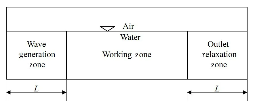
Fig.1 Layout of the numerical wave tank
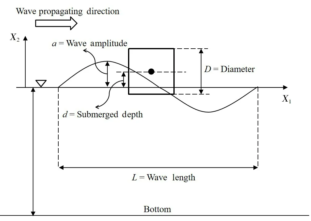
Fig.2 Definition sketch of wave-structure interactions for a square structure

Tab.1 Simulation cases of wave-structure interactions for a square structure
2 Mesh and time-step refinement study
In order to improve the numerical efficiency and accuracy,the mesh and time-step refinement studies are conducted firstly to obtain the optimal mesh and time-step.
Case T3 is used in the refinement study of wave-structure interactions for a square structure.The reason is that the flow field of Case T3 is the most complicated in all the cases due to the occurrence of the wave run-up and over-topping phenomena.Thus, the mesh and time-step determined in Case T3 is most appropriate and suitable for other cases in the present study.In addition,the vertical wave force coefficientF'vis introduced as the judging basis and subsequently compared between different meshes and time-steps in this chapter.
In the mesh refinement study, three sets of meshes with the same layout are investigated.The detailed parameters of three meshes have been presented in Tab.2.As shown in Fig.3,the vital area in the vicinity of the square structure is divided into two parts, i.e., the boundary layer region and the refinement region.And the closer the distance to the structure is,the smaller the mesh becomes.The change of meshes in the entire flow field is smooth so that the continuous flow field characteristics can be captured.The maximum Courant number of 0.3 with the adaptive time-step scheme is employed in the mesh refinement study.Fig.4 shows the numerical result of the mesh refinementstudy in terms ofF'vversust'over one wave period.It is obvious that Mesh b and Mesh c are able to capture more features of the vertical wave force than Mesh a,especially for a sudden fluctuation during the stage of valley values.Moreover,the curve ofF'vobtained by Mesh b is nearly identical with that measured by Mesh c, which further demonstrates that Mesh b is capable of providing enough numerical accuracy.

Tab.2 Grid resolutions for Case T3
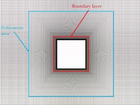
Fig.3 Zoom-in view of Mesh b
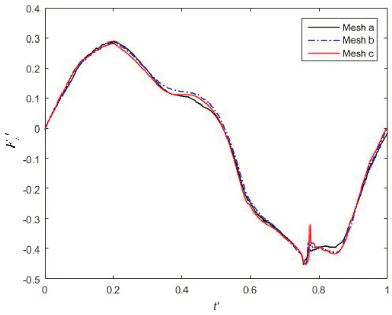
Fig.4 F'v with different meshes over one wave period for Case T3
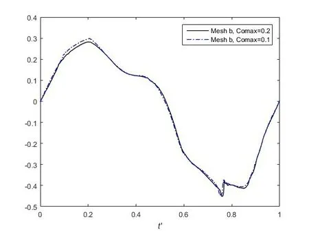
Fig.5 F'v with different time-steps over one wave period for Case T3 based on Mesh b
In the time-step refinement study, the maximum Courant numbers of 0.2 and 0.1 are investigated on the basis of Mesh b.The numerical result of the time-step refinement study is presented in Fig.5.It is clear that the two curves almost coincide.It proves that the maximum Courant number of 0.2 has the sufficient numerical accuracy.
In summary, Mesh b with the maximum Courant number of 0.2 is considered to have a sufficient numerical accuracy for simulating the wave-structure interactions of a square structure with different submerged depths.
3 Validation study for the present numerical model
In order to ensure the correctness of the present numerical study, a validation study for the present numerical model is carried out firstly.Due to the lack of the references for the square structure, the experiment data published by Dixon et al (1979)[17]for a circular structure with same con-figurations are used in this chapter.Three cases are investigated and the detailed parameters are listed in Tab.3.It should be noted that the mesh and timestep employed in this chapter is also determined by conducting the mesh and time-step refinement study.

Tab.3 Simulation cases of wave-structure interactions for a circular structure
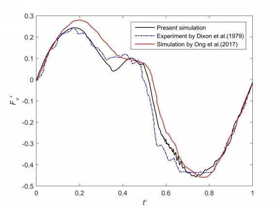
Fig.6 F'v versus t'over one wave period for Case S1
Fig.6 shows the numerical result calculated by the present numerical model and the experimental result measured by Dixon et al (1979)[17]for Case S1.It can be observed clearly that the present numerical result agrees with the experimental data well, especially for the peak and valley values.The numerical results obtained by Ong et al (2017)[13]based on thek-ωturbulence model is also presented in Fig.6.By comparison,it is found that thek-ωSST turbulence model employed in the present study is capable of capturing more characteristics of the vertical wave force on the square structure than thek-ωturbulence model.Figs.7-8 present the comparisons of the numerical and experimental results for Cases S2 and S3,respectively.It is clear that the curves computed by the present numerical model almost coincide with the experimental curves.
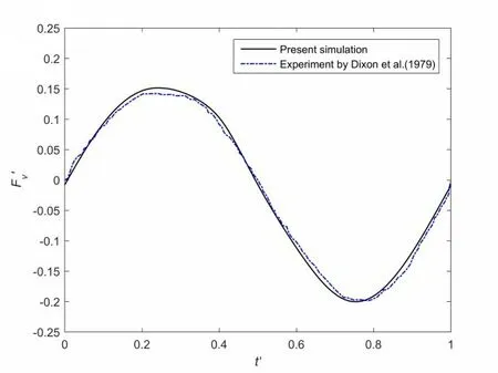
Fig.7 F'v versus t'over one wave period for Case S2

Fig.8 F'v versus t'over one wave period for Case S3
In general,the present numerical model is considered capable of capturing the detailed characteristics of wave force well.Thus,the present numerical model will be used to investigate the wavestructure interactions of a square structure with different submerged depths.
4 Results and discussions
Five simulation cases are performed to investigate the effect of the square structure's submerged depth on its hydrodynamic performances.
The numerical results of five cases are presented in Fig.9 for comparison and discussion.It can be easily concluded that the submerged depth of the structure plays an important role in the vertical wave force due to the remarkable differences among five curves.More detailed analyses for each case are stated as follows:
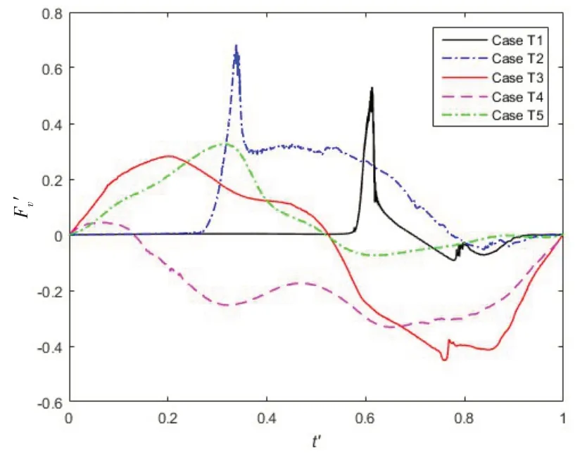
Fig.9 F'v versus t'over one wave period for a square structure
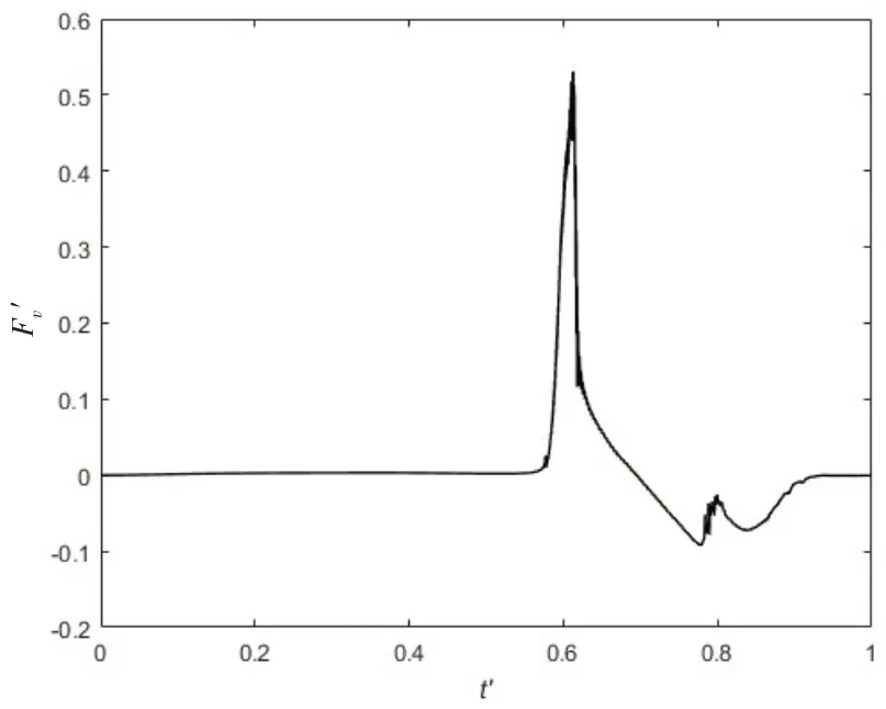
Fig.10 F'v versus t'over one wave period for Case T1
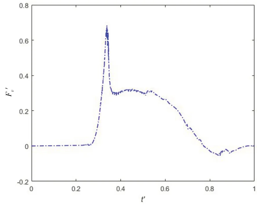
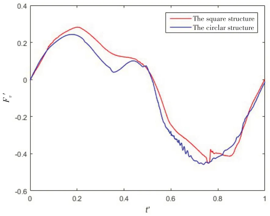
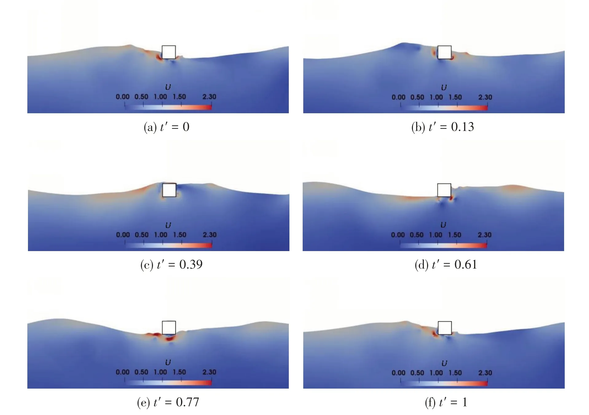
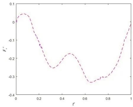
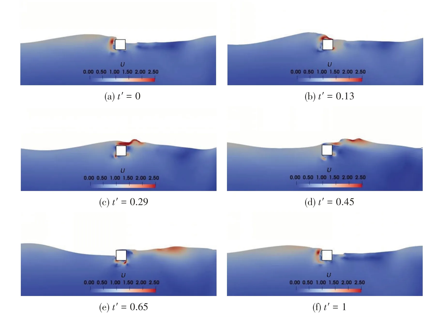
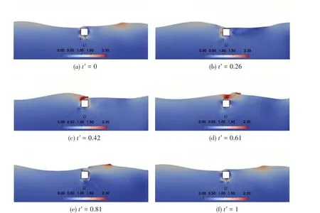
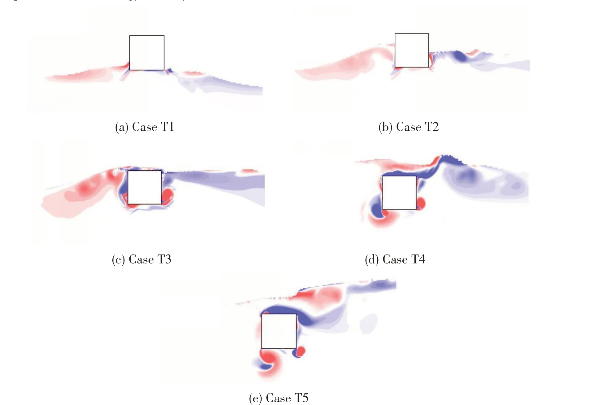
Fig.10 showsF'vversust'over one wave period for Case T1.It is clear thatF'valways keeps the level of 0 untilt'= 0.58.This is due to the fact that the structure is located at 0.9Dover the still water level and there is no interaction between the structure and waves during this stage.With the advent of the wave crest, the vertical wave force acting on the structure experiences a rapid increase andF'vincreases from 0 to 0.52 over the 0.03 wave period.Subsequently,the vertical wave force begins to decrease considerably andF'vfalls to its lowest point att'= 0.77 when the wave trough gradually approaches the structure.However,this process can be divided into two parts,i.e.,0.61 Fig.11 Time history of free surface elevations over one wave period for Case T1 Fig.12 F'v versus t'over one wave period for Case T2 Fig.12 showsFv'versust' over one wave period for Case T2.It is easily found that the trend ofin Case T2 is similar to that in Case T1.It can also be concluded that the wave impact force plays a dominant role in the vertical wave force for Case T2 due to the fact that the structures is also located above the still water level.However, the peak value ofF'vin Case T2 is larger than that in Case T1.The reason can be explained as follows:the distance between the structure and the still water level in Case T2 is smaller than that in Case T1.Thus, the structure in Case T2 has a deeper transient submerged depth than that in Case T1 when the wave crest passes through the structure, which further causes a larger wave impact wave.Fig.13 presents the free surface elevations over one wave period for Case T2.Similarly,the wave over-topping phenomena can be hardly observed due to the same reason with Case T1.However,the wave run-up actions are apparent,see Fig.13(d). Fig.13 Time history of free surface elevations over one wave period for Case T2 Figs.14 and 15 showF'vdistribution and the time history of the free surface elevations over one wave period for Case T3, respectively.In Case T3, the centre of the structure is located at the still water level and its side length is equal to the wave height.Thus, there are chances for the square structure to experience the fully-submerged and dry states.To be specific,F'vfirstly experiences a rise and reaches its first peak value aroundt'= 0.20.The rise can contribute to the wave run-up action which can be observed in Fig.15(b).Then,it undergoes a smooth decrease during 0.20 Fig.14 F'v versus t'over one wave period for Case T3 Fig.15 Time history of free surface elevations over one wave period for Case T3 Fig.16 F'v versus t'over one wave period for Case T4 Fig.17 Time history of free surface elevations over one wave period for Case T4 Fig.18 F'v versus t'over one wave period for Case T5 Fig.18 presentsF'vdistribution over one wave period for Case T5.Fig.19 shows the free surface elevations over one wave period for Case T5, respectively.In this case, the center of the square structure is located at 1Dbeneath the still water level.Therefore, the square structure always keeps the fully-submerged state during the whole simulation, see Fig.19.Due to the lack of the free surface's disturbance,the wave force acting on the structure in Case T5 is the simplest in all the simulation cases:F'vrises when the wave crest approaches the structure and descends when the wave trough passes the structure.In summary,the vertical wave force on the structure is affected strongly by the pressure field of waves. Fig.19 Time history of free surface elevations over one wave period for Case T5 Moreover, the over-topping phenomenon with the wave breaking physics can be observed clearly in Cases T3,T4 and T5,this is due to the fact that the square structure in Cases T3,T4 and T5 are located at a low position.It is much easier for the wave crest with a high speed to impact the top of the square structure.Subsequently, the vertical fluid velocity reduces rapidly to 0 within a short time. The critical time instants of the incident wave past the twin-square structure in Cases T1, T2,T3, T4 and T5 are shown in Fig.20.The vorticity generation and shedding phenomena around the square structure are more prominent with the increase of the submerged depth of the structure.It also demonstrates that the sharp corner is able to disturb the motion trails of the fluid particles and dissipates the wave energy directly. Fig.20 Critical time instants of the incident wave past a square structure in different cases In summary,it appears that the present numerical model is considered to be capable of capturing the vertical wave force on and simulating the free surface elevations and vorticity in the vicinity of the square structure. The wave-structure interaction for a square structure with different submerged depths is studied numerically by employing the URANS equations and thek-ωSST turbulence model.And the VOF method is employed to capture the characteristics of the free surface.The submerged depth of the square structure varies from -1Dto 0.9Din the present study.The vertical wave forces on and the free surface elevations and vorticity in the vicinity of the square structure are analyzed. The structure experiences the largest positive wave force whend'= 0.5, and the largest negative wave force occurs whend'= 0.Meanwhile, the peak-valley value is the largest whend'= 0.Thus,the main conclusions are summarized as follows: For the structure originally located over the still water level, the wave impact phenomenon is obvious.Thus, the structure is easily subjected to a larger vertical wave force in a very short time,which should draw engineers' attention.For the partially-submerged structure during the whole simulation, the disturbance of the free surface can strongly affect the vertical wave force on the structure.In this condition, the flow field is complex due to the occurrence of the wave run-up and over-topping phenomena.For the structure remaining in the-fully submerged state during the whole simulation, the vertical wave force is mainly affected by the pressure field of the incident waves due to the lack of the free surface's disturbance.In addition, the vorticity generation and shedding phenomena at the sharp corner of the square structure are more prominent with the increase of the submerged depth of the structure.It also demonstrates that the sharp corner is able to disturb the motion trails of the fluid particles and dissipate the wave energy directly.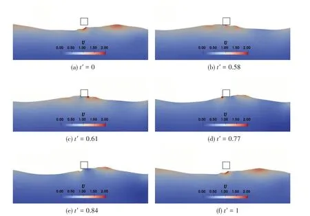


5 Conclusions

