
Mechanical properties and damage characteristics of solidified body-coal combination in continuous driving and gangue backfilling
2023-12-14 12:13:16YiTnHoChengWenbingGuoErhuBiShopuZhngYuWngZihoLi
矿业科学技术学报 2023年10期
Yi Tn ,Ho Cheng *,Wenbing Guo ,Erhu Bi ,Shopu Zhng ,Yu Wng ,Ziho Li
a School of Energy Science and Engineering, Henan Polytechnic University, Jiaozuo 454000, China
b State Collaborative Innovation Center of Coal Work Safety and Clean-Efficiency Utilization, Henan Polytechnic University, Jiaozuo 454000, China
Keywords:Continuous driving and gangue backfilling Solidified body-coal combination Mechanical properties Damage characteristics Digital image correlation technology Acoustic emission
ABSTRACT Recovery of the coal buried under buildings,railways and water bodies and the residual coal in irregularly arranged fully mechanized mining faces is a common engineering problem facing underground coal mining.In this study,a mining technology of continuous driving and gangue backfilling (CDGB) was proposed.The technology,which can not only alleviate ground subsidence and gangue discharge,but also release the above-mentioned coals,contributes to green and efficient sustainable development of mining.The stability of the system of the solidified body-reserved coal pillar combination (S-C combination) is crucial to the CDGB technology.Therefore,it is of great significance to explore the mechanical and damage characteristics of S-C combination in the synergistic bearing process.First,four sets of differentshaped S-C combination specimens were fabricated and a S-C combination bearing structure in CDGB was constructed to explore the differences in mechanical characteristics and damage modes of different-shaped S-C combination specimens during CDGB.Subsequently,their surface strain field evolutions and acoustic emission(AE)response characteristics in the load-bearing process were obtained with the aid of the digital image correlation technique and the AE signal monitoring system.Furthermore,a damage evolution model based on AE parameters and mechanical parameters was established to clarify the damage evolution law.The following results were obtained:(1)The free area of S-C combination can serve as a quantitative index to evaluate the stability of the overburden control system;(2)The concept of critical value k of the free area was first proposed.When the free area exceeds the critical value k(free area ratio greater than 1.13),the deformation resistance and the free area changes becomes negatively correlated;(3)As the free area expands,the failure of the S-C combination specimen evolves from tensile failure to shear failure.The distribution characteristics of the axial strain field also verified such a change in the failure mode;(4)When the free area expands,the peak AE count gradually changes from ‘‘double peaks” to ‘‘a single peak”.In this process,the expansion of free area shortens the time for accumulating and releasing energy during loading.Micro cracks generated in the specimen change from a phased steep growth to a continuous increase,and the process in which micro cracks develop,converge,intersect and connect to form macro cracks accelerates.The damage evolution law concluded based on AE parameters and mechanical parameters can well characterize the damage evolution process of S-C combination,providing certain reference for the study on the synergistic bearing of S-C combination during CDGB.
1.Introduction
Coal mining may cause surface subsidence and ecological damage[1,2].Gangue backfilling is one of the green technologies developed for facilitating safe mining of coal resources under buildings,railways and water bodies,coping with the disposal of coal gangue and preserving land resources in China.The technology has served for dealing with gangue solid waste,controlling mining-induced surface subsidence and protecting the environment in major mining countries [3-5].Currently,since China attaches great importance to ecological environmental protection,mine solid waste discharge reduction and ecological construction are becoming increasingly strict and urgent.The important role of gangue backfilling is increasingly highlighted,as it is in line with the development strategy of ecological civilization construction and environmental protection [6,7].
Research has demonstrated that many old mines are plagued by resource depletion,while there exist many coal resources under buildings,railways and water bodies and massive residual coal resources in places where regular fully mechanized working faces fail to be arranged[8-10].In response to these problems,with reference to the previous experience of the strip Wongawilli coal mining technology [11] and the engineering practice,the team of authors combined continuous driving with gangue backfilling to control the roof and reduce the subsidence.This continuous driving and gangue backfilling (CDGB) technology not only solves the problem of gangue disposal in mines but also realizes efficient and safe mining of coal resources under buildings,water bodies and railways and irregular residual coal resources,thus extending the service life of mines.
In recent years,in order to adapt to various geological mining conditions,scholars have put forward a variety of improved methods and techniques on the basis of gangue backfilling,including strip mining,coal pillar-gangue replacement mining and shortwall gangue cemented filling [12,13].Xu et al.[14] proposed the technology of strip filling in the goaf.In this technology,a part of space in the goaf is filled after coal seam recovery and before roof caving to construct alternate filling strips which serve to support the overlying strata and control the surface subsidence.Du et al.[15] proposed a construction backfilling coal mining technology that can reduce the filling cost,and determined the deformation characteristics and filling spacing of the roof in this technology.
From the perspective of deformation strength and damage characteristics of gangue-filled aggregate under loading,scholars have carried out extensive mechanical experimental studies on the filling materials under different conditions (such as different grades and lateral pressures) [16-19].The following researches are focused on the properties of filling materials.Huang et al.[20]explored the macro motion behaviors and micro motion characteristics of the filling body under triaxial compression by numerical simulation,and clarified the positive effect of the motion of small particles on the bearing capacity.Zhang et al.[21]conducted compression experiments on gangue filling materials,found the differences between the deformation modulus of gangue filling materials in the experimental environment and the engineering environment,and proposed the corresponding correction coefficient.In addition,some researchers focused on the replacement of cement-based binders in filling materials,such as microbialinduced carbonate precipitation,and then proposed the corresponding microbial grouting and backfilling technology [22,23].
Experiments were also performed on specimen size and shape effect[24,25].Du et al.[26]explored the shape effect of rock specimen under uniaxial compression and evaluated the dependence of the uniaxial compressive strength of rock specimens on their shapes and sections,which provided a reference for the design of underground hard rock mine pillars.Das [27] found out the influence of width-to-height ratio on post-peak failure behaviors of coal specimens.Jamshidi et al.[28]revealed the influence of travertine specimen diameter on uniaxial compressive strength and P-wave velocity through mechanical experiments on specimens with different diameters,and obtained the optimal diameter of travertine specimens.
In summary,scholars have optimized filling technologies under specific conditions by applying filling technologies extensively,and explored the mechanical properties of the filling body and the residual coal pillars after filling,providing theoretical technology and data support for backfilling mining.A great deal of research has focused on longwall fully mechanized backfilling mining.In contrast,relatively few studies have been reported on CDGB,especially on the mechanical properties and bearing capacity of the combination of gangue-filled solidified body and coal (hereafter referred to as S-C combination) during CDGB mining,which are the key to overburden control in CDGB.Hence,the mechanical properties and bearing capacity of S-C combination deserve further research.
In the 1990s,the digital image correlation (DIC) technique has been widely adopted in experimental research in the field of rock mechanics [29].Recently,McNeill et al.[30] proposed a method for estimating the stress intensity factor by the DIC technology.Lotidis et al.[31]studied the influences of material and pore diameter on the fracturing process of specimens by DIC and AE,and then proposed a new method to accurately determine the initial fracture and failure time through the DIC technology.Corr et al.[32] recorded and analyzed the interfacial debonding properties and fracture behaviors in concrete through the DIC technology,and determined the accuracy of the DIC technology in monitoring material deformation.In addition,as it is difficult to directly observe the damage evolution in the filling body under loading,the damage degree and damage process in the S-C combination can be well demonstrated through nondestructive experimental technologies such as AE [33,34].Prˇikryl et al.[35] accurately described the microstructure evolution characteristics during specimen loading by monitoring the compression process of rock specimens through the AE technology.Cox et al.[36] applied the AE technology to the monitoring of microcracks formation and material softening in rock,combined the cumulative state of specimen damage obtained by the AE technology with the prediction model of cracked solid softening behavior,and determined the feasibility of the model in predicting the mechanical behaviors of specimens.
In this study,the evolution characteristics of the strain field on the specimen surface during loading were obtained by DIC,and the AE signals were recorded as well.On this basis,the damage evolution processes of the specimens were analyzed.
2.Innovative CDGB mining technology
2.1.Working face layout
The layout of the working face resembles that of roadway excavation.First,the belt conveyor roadway,the return air roadway and the filling roadway are excavated in advance to form a fullnegative-pressure ventilation system.Subsequently,different filling areas are divided according to the lengths of branch roadways,and no coal pillars are retained between two adjacent filling areas;the filling roadway serves both filling areas by strengthening the support,and protective coal pillars are arranged between the belt conveyor roadway and the filling equipment chamber.The coal seam to be mined within the filling area is divided into several branch roadways of certain widths along the filling roadway.In these branch roadways,coal is recovered by continuous shearers or roadheaders.During filling,a slurry retaining wall and a drainage pipe are installed in the branch roadways for the purpose of water drainage during initial filling.The filling material is transported from the upper port of the branch roadway to ensure the quality of filling and the integrity of roof joint.The layout of the working face roadway is shown in Fig.1.
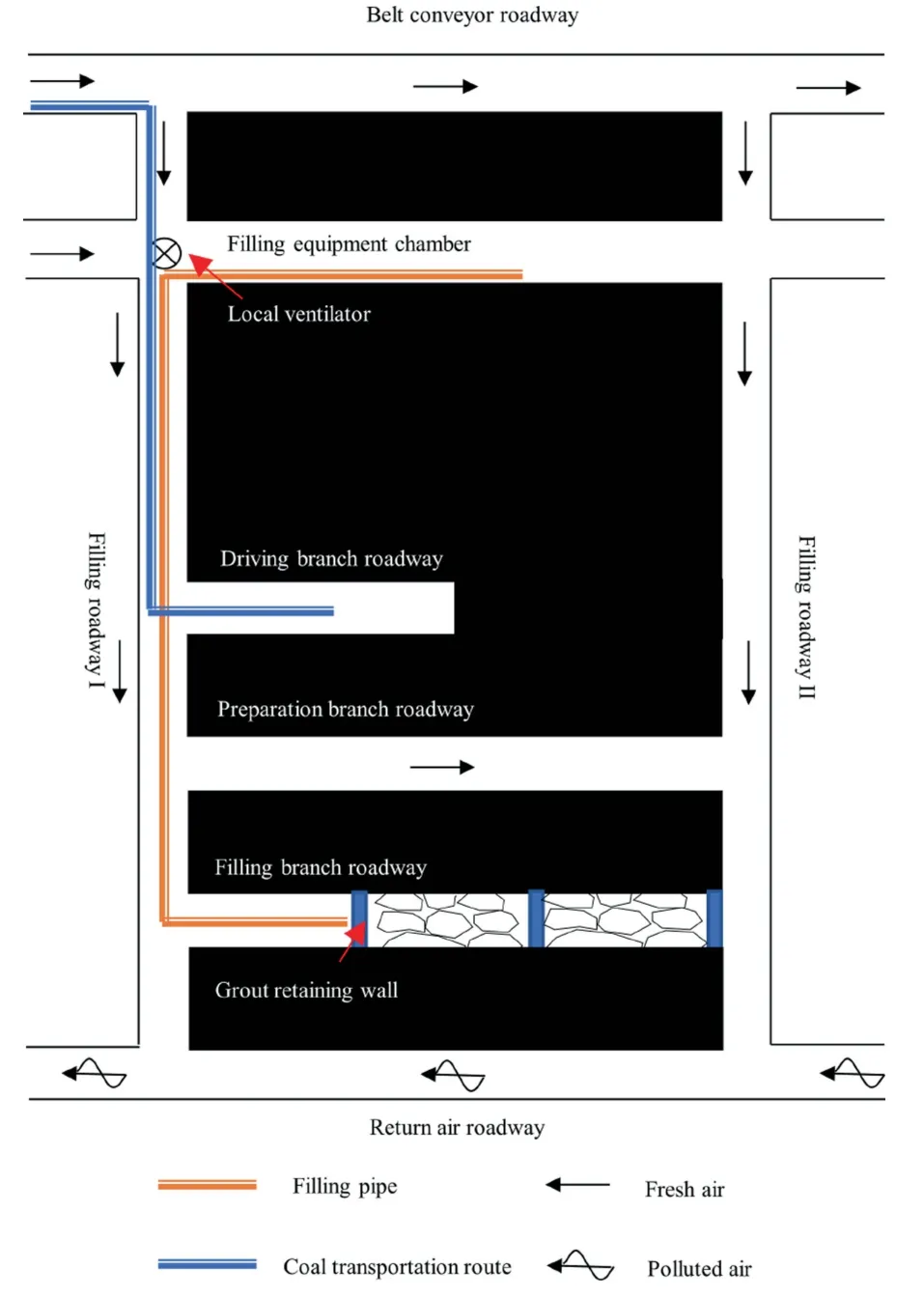
Fig.1.Layout of working face roadways.
2.2.Procedure of continuous driving
In order to improve the efficiency of driving and filling,two branch roadways are spaced apart according to the principle of‘‘driving,preparation and filling” (Fig.2).
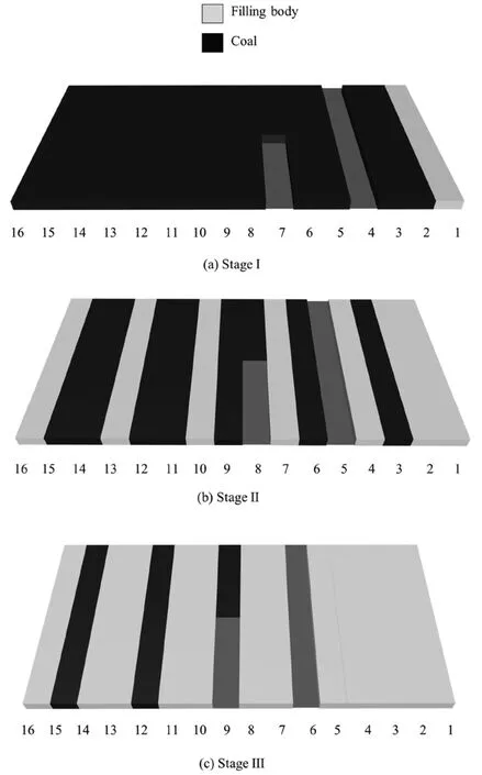
Fig.2.Operation mode of CDGC.
According to the nature of support bodies on both sides of branch roadways during continuous driving,the whole process of CDGB is divided into three stages.
In Stage I (Fig.2a),both sides of branch roadways are coal pillars.When coal falls in branch roadways,branch roadways Nos.1,4,7,10,13 and 16 are excavated in turn and two branch roadways are left between the driving roadways.In accordance with the principle of‘‘driving,preparation and filling”,after the excavation of the first branch roadway (No.1) completes,the second branch roadway(No.4)starts to be excavated.After its excavation finishes,it will be taken as a backup filling roadway.At this time,the excavation of the third branch roadway (No.7) and the filling of the branch roadway No.1 start.In the same manner,the excavation and filling of branch roadways Nos.1,4,7,10,13 and 16 are completed in turn.
In Stage II(Fig.2b),one side of the branch roadways is the initial solidified body and the other side is coal pillars.In this case,branch roadways Nos.2,5,8,11 and 14 are excavated in sequence and filled in time.During CDGB,it is always ensured that the protective coal pillar (or solidified body pillar) between the excavation and filling branch roadways is twice as wide as the branch roadway or the solidified body.
In Stage III (Fig.2c),both sides of the branch roadways are the solidified body.After the solidified body has reached support strength,the branch roadways Nos.3,6,9,12 and 15 are then excavated in turn and filled in time to complete the entire work of driving and filling in the filling area.
The filling roadway and the filling branch roadway may be connected in a variety of ways on site,resulting in different combinations of the solidified body and the reserved coal body at the joint.The bends between the filling roadways and the filling branch roadways are the stress concentration zones which are often the most susceptible to damage.Moreover,the solidified bodies and the coal pillars in these areas play different roles in maintaining the overall stability of overlying strata,forming a kind of S-C combination bearing structure(Fig.3).Thus,the deformation and damage characteristics of the S-C combination bearing structure need to be further investigated.
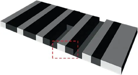
Fig.3.S-C combination bearing structure.
3.Preparation of different-shaped S-C combinations and test scheme
As illustrated in Fig.4,the S-C combination bearing structure in the practical continuous excavation and backfilling process has demonstrated an irregular shape as a result of on-site construction.Furthermore,the bearing structure is situated in a highly stressful region,specifically the turning point where the backfilling roadway and the backfilling support roadway meet.
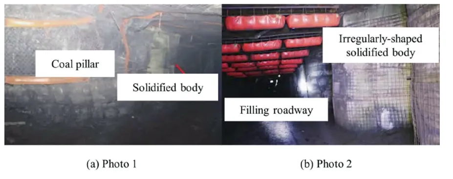
Fig.4.Photos of the S-C combination bearing structure [37].
Irregularly-shaped stones are located in the stress concentration zone on the CDGB site,and the reserved coal pillars are vulnerability to damage.In view of the above problems,three different shapes of S-C combinations were designed whose cross-sections were round,square and diamond respectively.Furthermore,given different combination modes of the solidified body and the reserved coal pillar,a set of square (diagonally cut) specimens were supplemented as a comparison.With the cross-sectional areas and heights of the specimens controlled the same,the effect of different shapes on the mechanical properties and damage characteristics of S-C combinations was explored.The indoor experimental models of the S-C combination bearing structure are illustrated in Fig.5.
3.1.Preparation of S-C combination specimens
The fabrication process of the solidified body part of the specimens is described.First,according to the crushing ratio of the double-rotor crusher on the CDGB site in Daning Coal Mine in Shanxi Province,China,the gangue was screened into 0-1,1-5 and 5-20 mm which accounted for 40%,40% and 20% of the total gangue content,respectively.Next,mix the crushed and screened coal gangue,sand,and ordinary Portland cement (OPC 42.5)according to a mass ratio of 6:4:1 to prepare a paste filling slurry,and stir evenly.Afterwards,the slurry was placed into a mold with the size of 400 mm × 300 mm× 140 mm.After 24 h of static settling,the mold was removed to obtain the formed specimen.According to the results of XRD,PSD and microscopic morphology tests conducted by Wu et al.[38] on ordinary Portland cement(OPC 42.5) and composite Portland cement (CPC 32.5),OPC 42.5 exhibits superior adhesive properties.It should be noted that the specimens made according to this composition and ratio were all paste specimens.
Subsequently,the specimens were cured in a curing room at a temperature of 20 °C and the relative humidity of 95% for 28 d[39],after which they were processed by an RCD-250 diamond machine,an RLS-100 stone sawing machine,an RSG-200 stone grinding machine and a wire cutter.The coal part of the specimens was taken from the CDGB site in Daning Coal Mine and processed with the same equipment above.Finally,the processed solidified body and coal were glued together with marble glue and left to stand for 24 h.The final specimens are displayed in Fig.6 and their dimensional parameters are listed in Table 1.
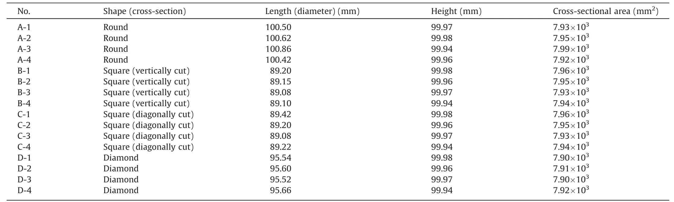
Table 1 Sizes of different-shaped specimens.
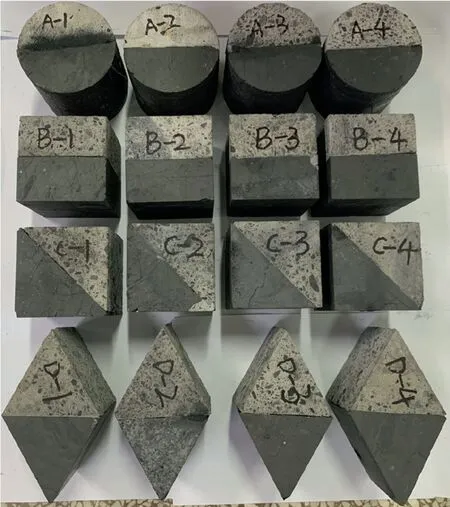
Fig.6.Finished products of different-shaped specimens.
3.2.Test equipment and scheme
The main test equipment comprised an RMT-150B loading system,an AE monitoring system and a non-contact full-field strain monitoring system (Fig.7).
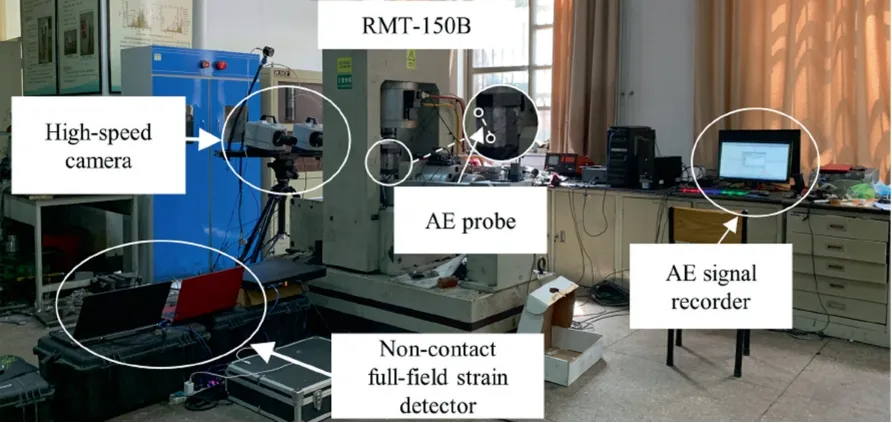
Fig.7.Uniaxial compression test equipment.
Test scheme: Prior to the test,black scatter spots on a white background were made on the surface of the specimens with a matt spray paint,and the lens of the high-speed camera was calibrated.Then,conventional uniaxial compression tests were carried out on S-C combination specimens of different shapes using the RMT-150B rock mechanics testing system.The test adopted displacement loading control with a loading speed of 0.002 mm/s.During the loading process,the non-contact full-field strain monitoring system and the AE monitoring system (Physical Acoustics,the USA) were used to capture AE signals and strain field changes on the specimen surface.In order to achieve good acoustic coupling,a thin layer of petroleum jelly was applied to the AE sensor as a coupling agent.
4.Analysis on test results of different-shaped S-C combinations
4.1.Concept of free area
To explore how shapes influence the mechanical characteristics and failure forms in the bearing process,a concept of ‘‘free area”was proposed to quantify the shape.In the uniaxial compression experiments,the free area is the side area of the specimen.
Table 2 shows the parameters of free areas and bonded areas of S-C combination specimens with four different shapes.
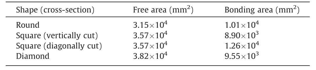
Table 2 Parameters of free areas and bonded areas of S-C combination specimens.
4.2.Influence of free area on mechanical properties of S-C combination
4.2.1.Stress-strain curves
The stress-strain curves of different-shaped S-C combination specimens are illustrated in Fig.8.Their loading processes can all be divided into four stages,which are the original pore compaction stage,the elastic extension stage,the plastic development stage and the post-peak damage stage.
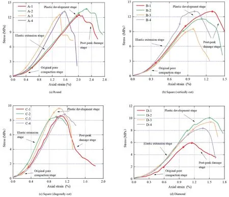
Fig.8.Stress-strain curves of different-shaped specimens.
In the original pore compaction stage,the original open structural plane and original pores of the specimen gradually close under the action of axial pressure,the curve grows nonlinearly.As the upper load gradually increases,the specimen deformation enters the elastic extension stage in which its stress-strain curve presents a first-order linear growth.In the plastic development stage,micro rupture accelerates within the specimen,resulting in the overall damage intensifies.Hence,the strain surges and the stress peaks.After reaching the peak,it enters the post-peak damage stage where fractures develop,converge,intersect and connect with each other rapidly.Hence,macroscopic damage occurs,and the bearing capacity of the specimen decreases with the intensification of deformation.
Different-shaped S-C combination specimens differ greatly in their yield characteristics of plastic development stage and their weakening characteristics of post-peak damage stage.Compared with specimens of other shapes,round specimens (Fig.8a) have no obvious yield platform at the peak strength.However,they exhibit obviously different characteristics in different stages during the weakening process,and their stress drops in a stepped manner.In the post-peak macro crack sliding process,the characteristics of climbing and gnawing teeth can be easily noted,displaying stronger brittleness.This demonstrates that the free area has a certain influence on the brittleness and plasticity.Specifically,the brittleness weakens and the plasticity strengthens with the increase in the free area.
4.2.2.Elastic modulus
By considering the free area of the cylindrical specimen as 1,the relationships between the elastic moduli and the free area ratios of different-shaped specimens are derived (Fig.9).As the free area ratio grows,the elastic modulus first increases and then decreases.Compared with the elastic modulus of the round specimen,those of the vertically cut and diagonally cut square specimens rise by 58.1% and 16.2%,while that of the diamond specimen falls by 17.6%.

Fig.9.Relationships between elastic moduli and free area ratios of differentshaped specimens.
It can be concluded that a certain degree of increase in free area can improve the stiffness of S-C combination,but the ability of the combination to resist deformation weakens after the free area ratio exceeds a critical value (kgreater than 1.13).For the two square specimens with the same free area,the elastic modulus of the vertically cut one is significantly greater than that of the diagonally cut one.It is inferred that the bonded area of the vertically cut one is comparatively smaller,their bonded area ratio being 1:1.4.Such a result suggests that the deformation resistance decreases with the increase in bonded area.
4.2.3.Peak strain
The relationships between peak strain and free area ratios for different-shaped specimens are presented in Fig.10.As the free area ratio grows,the peak strain decreases first and then increases.Compared to the round specimen,the peak strains of the vertically cut and diagonally cut square specimens and the diamond specimen drop by 42.6%,43.2% and 24%,respectively.However,compared with the diagonally cut square specimen (free area ratio 1.13),the peak strain of the diamond specimen (free area ratio 1.21) only increases by 33.7%,suggesting that the diamond specimen suffers more serious damage in the pre-peak stage.A comparison between the two specimens with the same free area ratio reveals that their peak strains barely differ,which shows that the bonded area has almost no effect on the peak strain.
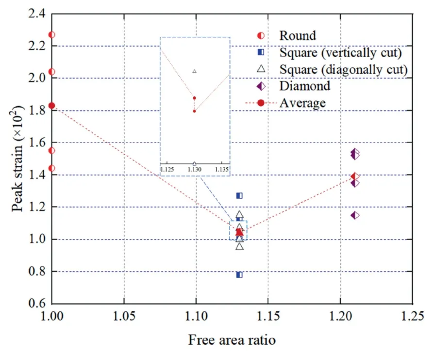
Fig.10.Relationships between peak strains and free area ratios of different-shaped specimens.
4.2.4.Weakening modulus
‘‘Weakening modulus” refers to the slope of the approximate linear segment in the post-peak failure stage.Different-shaped specimens display different characteristics in the post-peak damage stage.The weakening modulus in Fig.11 can reflect the degree of damage weakening for different-shaped specimens.The smaller the free area ratio,the greater the weakening modulus,illustrating faster stress drop and more pronounced brittle characteristics.According to the comparison between the two specimens with the same free area ratio,the weakening modulus of the diagonally cut square specimen is smaller,which means that the different combination modes between the solidified body and coal have an obvious effect on the post-peak load-bearing capacity of the specimen.The larger the bonded area,the stronger the plasticity.
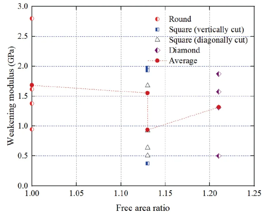
Fig.11.Relationships between weakening moduli and free area ratios of differentshaped specimens.
4.2.5.Peak strength
The relationships between peak strength and free area ratios of different-shaped specimens are given in Fig.12.
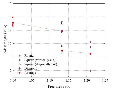
Fig.12.Relationships between peak strengths and free area ratios of differentshaped specimens.
From Fig.12,it is clear that an increase in free area reduces the load-bearing capacity of the S-C combination to some extent.By comparing the two specimens with the same free area,it is found that the peak strength of the vertically cut square specimen is notably higher than that of the diagonally cut one,implying that the compressive strength decreases with the increase in bonded area.
4.3.Damage characteristics
Some differences can be observed in the failure modes of different-shaped specimens (Fig.13).
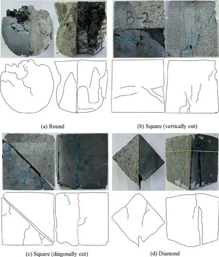
Fig.13.Failure modes of different-shaped specimens.
From Fig.13a,during loading of the round specimen,the damage of the main shear surface terminates from one end of the specimen to the other,penetrating the specimen from the left to the right.When the specimen loses stability,part of the stress concentration zone breaks into powder.Tension cracks are evident in the solidified body part(right side),which indicates the dominant role of tensile failure.The coal part(left side)also primarily experiences tensible failure,accompanied by local shear failure and significant ejection damage during loading.The specimen tends to form a combination conical residual zone.
The damage to the main shear face of the vertically cut square specimen (Fig.13b) is predominantly located in the coal part.The cracks in the coal part(left side)extend upwards from the bottom end face in tension and fail to penetrate the specimen,and those in the solidified body part (right side) extend from the end face downwards to the left,where tensile failure is dominant.
From Fig.13c,during loading,the damage to the diagonally cut square specimen is mainly tensile failure,and the two parts separate at the intersection.At the main shear plane,damage to the coal part is severer than that to the solidified body part,manifested by the fact that the coal part has more cracks which extend from one end of the specimen to the intersection.Tensile cracks are evident in the coal part and penetrate the specimen vertically,while no visible cracks occur in the solidified body part,with only spalling damage at the corners.
The diamond specimen (Fig.13d) mostly undergoes shear failure during loading,accompanied by local ejection damage and separation of the two parts at the intersection.At the main shear plane,the damage to the coal part is similar to that to the solidified body part.In both of them,cracks appear in the middle section of the specimen,extend towards the boundary,but fail to penetrate the specimen.The coal part mainly experiences ejection damage,while the solidified body part primarily presents shear failure with significant shear-slip cracking.
4.4.DIC-based load-bearing characteristics
The DIC technology is employed to monitor the surface strains in real time in the load-bearing process of S-C combination specimens with round,square (vertically cut) and diamond cross sections.To focus on the bearing characteristics from the plastic development stage to the post-peak damage stage,characteristic points of 80%,90%,and 100% peak strength before the peak stage and of 90% and 80% peak strength after the peak stage were selected for analysis (Fig.14).For accuracy of the data,the central rectangular area of the specimen is selected for analysis,with the coal part on the left and the solidified body part on the right.The strain field range is approximately 1/3 of the complete surface of the specimen.
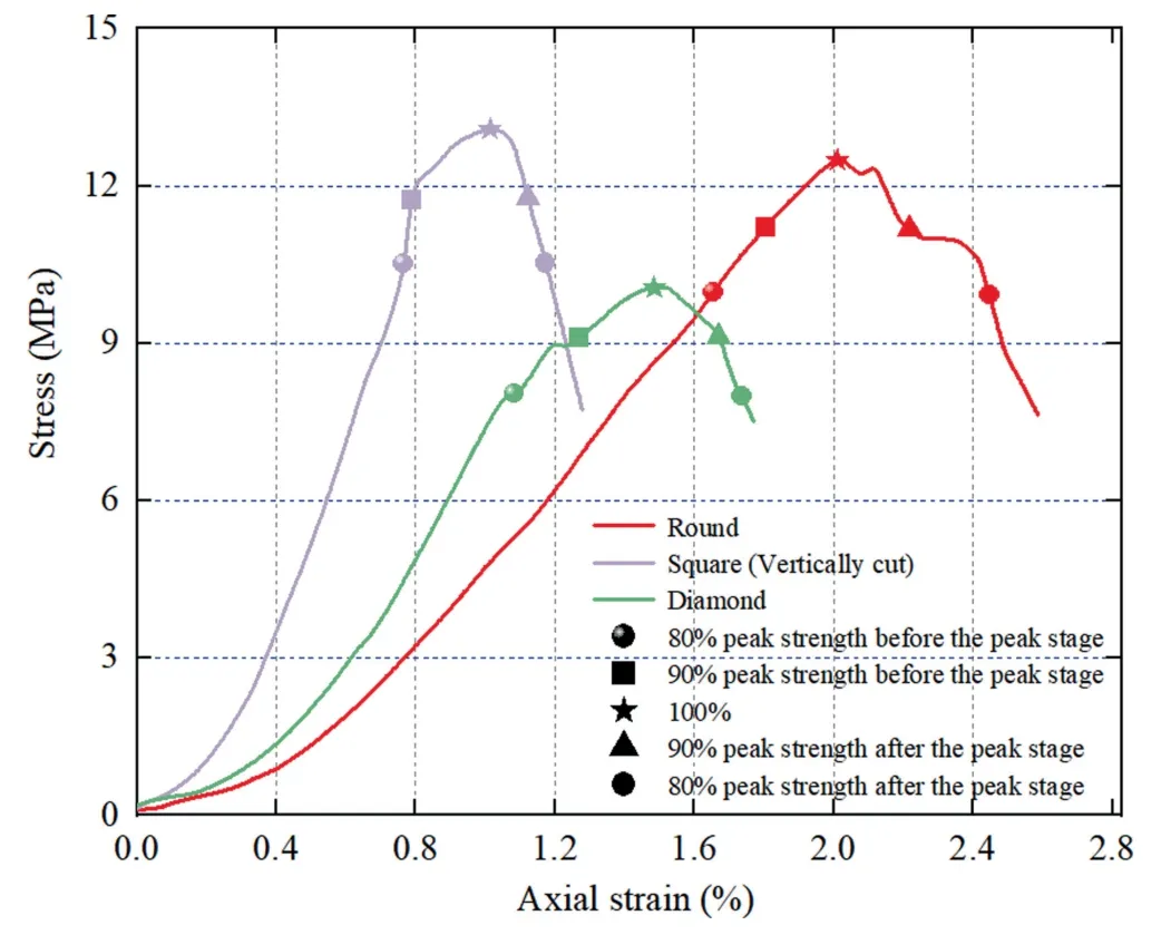
Fig.14.Stress-strain curves and characteristic points of different-shaped specimens.
As shown in Fig.15a,in the pre-peak stage,when the round specimen reaches 80% of its peak strength,its peak strain field is evenly distributed overall.Strain is concentrated in blocks in the coal part(left side),and no obvious strain bands are formed.When it reaches 90%of its peak strength,a strain band connecting on the left and right end faces appears in the middle of the specimen,and the high-strain area is concentrated in the solidified body part(right side).It indicates that the axial deformations of the solidified body part and the coal part are no longer synchronized,and that of the solidified body part accelerates.When the specimen reaches peak strength,the maximum value of axial strain appears at the lower right of the specimen.A large number of micro cracks are gathered and connected in this area,and macro cracks begin to appear.With the continuous application of the load,the specimen enters the post-peak damage stage where the peak strength drops to 90% and then to 80%.The axial deformation of the specimen accelerates,and an axial strain aggregation area appears in the lower right part of the specimen,which expands along the diagonal to the upper right.The cracks converge and connect here,resulting in the release of strain energy.The stress-strain curve shows two stepped decreases,and the overall strength of the specimen decreases,eventually leading to instability failure.
Next day, accordingly, the old woman went to the Tsar s splendid Palace and fell to walking up and down before the windows. The servants came to ask her her errand but she answered them nothing, and kept walking up and down. At length the Tsar opened his window, and asked: What dost thou want, old woman, that thou walkest here?
The strain field evolution of the vertically cut square specimen in the pre-peak stage (Fig.15b) is similar to that of the round one,both changing from uniform distribution to localized belt formation.When the specimen reaches 90% and 100% of the peak strength in the pre-peak stage,the axial strain changes dramatically in the solidified body (right side) and the maximum value of the axial strain appears at the upper right of the specimen.In the post-peak damage stage,the strain forms a localized belt in the solidified body part,and the strain concentration zone where the maximum value of the axial strain is located extends from the end face to the lower left side.In the loading process,tensile cracks generated in the upper stress concentration region extend downwards.Compared with round specimen,its rate of strain concentration area expansion during the post-peak damage stage.In other words,the speed of crack convergence and connection and the release of strain energy in the area significantly increase,leading to a cliff-like drop in its stress-strain curve.
From Fig.15c,the strains in the coal part (left side) of the diamond specimen gather mostly in blocks during the loading process,and ejection damage occurs.The strain localization zone in the solidified body part (right side) climbs to form a righttriangle-shaped strain concentration zone,resulting in a shearslip crack with the strain zone as the extension path.Unlike the round specimen,its main failure mode is shear failure.
4.5.AE characteristics
To investigate the development of internal cracks and the characteristics of energy accumulation and release during specimen loading,the relationship among load,AE count and displacement during loading is plotted (Fig.16).For the round specimen,the peak AE count is characterized by ‘‘double peaks” throughout the loading process,and the cumulative AE count develops steadily first,then jumps and finally soars.Only a small number of AE activities can be observed in the original pore compaction stage.When the specimen enters the elastic extension stage,the AE activities become more frequent.In the late elastic extension stage,the accumulated elastic energy inside the specimen is released to form the first peak,and numerous cracks are formed inside the specimen.In the plastic development stage,micro rupture within the specimen accelerates,and the elastic energy inside the specimen exceeds the energy required for stable expansion of cracks.Resultantly,the energy is suddenly released,and the specimen fails,generating a few AE signals.At this point,the peak AE count jumps suddenly to the second peak.Meanwhile,from the plastic development stage to the peak damage,the peak AE count presents two peaks,which means that tiny fractures are continuously generated in the plastic stage.As a result,energy is accumulated,and each time the accumulated energy is higher than the previous one.
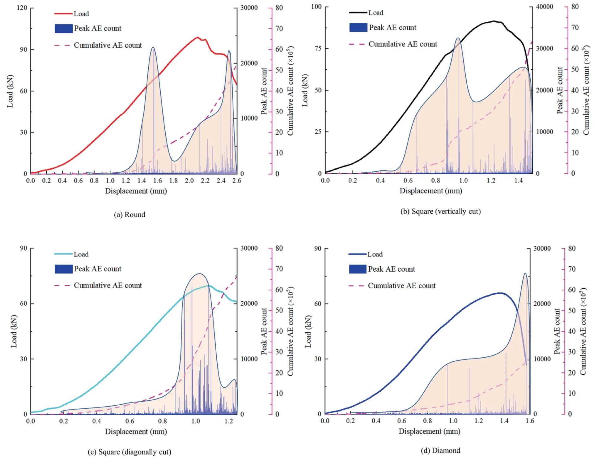
Fig.16.Relationships among AE counts,loads and displacements of different-shaped specimens.
The AE count of the square(vertically cut)specimen also shows‘‘double peaks”,but its characteristics differ from those of the round specimen.The first peak appears at the beginning of the plastic development stage due to the release of its elastic energy.However,it can be noted that in the elastic extension stage,unlike the direct jump of the AE count of the round specimen,the square(vertically cut) specimen experiences obvious sub-peak uplifting twice,indicating that its internal accumulated elastic energy has the characteristics of phased release.Compared with the second peak of the round specimen,that of the square (vertically cut)specimen also appears in the post-peak damage stage,but the AE activities on both sides of the peak are also active.Consequently,the ‘‘double peaks” are non-independent and tend to evolve into a ‘‘single peak”.
Different from the AE counts of round and square (vertically cut) specimens,the AE count of square (diagonally cut) specimen shows a ‘‘single peak”,and its ‘‘single peak” appears in the plastic development stage.Its energy release is relatively weak in the elastic extension stage,showing more obvious energy accumulation characteristics.The plastic development stage has three peaks of AE count and displays a slow increasing trend,showing a stronger internal reaction.The energy release stage is characterized by short accumulation time and high release intensity.
Similar to the AE count of the square(diagonally cut)specimen,that of the diamond specimen shows a ‘‘single peak” which appears in the post-peak damage stage.Before the appearance of the‘‘single peak”,the diamond specimen only experiences obvious sub-peak uplifting once and presents a‘‘pre-peak platform”.It indicates that the early loading stage witnesses a low energy release intensity,a gentle energy release process and obvious phased energy accumulation.
To sum up,the characteristic of AE count of the S-C combination specimens in the loading process is subject to the free area.As the free area expands,the AE count of the specimen gradually evolves from‘‘double peaks”to a‘‘single peak”.The expansion of free area shortens the energy accumulation and release time during loading.The micro cracks generated in the specimen change from a phased steep growth to a continuous increase,and the process in which micro cracks develop,converge,intersect and connect to form macro cracks accelerates.
5.Analysis on damage evolution of different-shaped S-C combinations in the load-bearing process
5.1.Analysis on damage evolution based on AE parameters
AE parameters can characterize changes in material properties[40].Here,cumulative AE count is chosen to investigate the damage characteristics of different-shaped specimens.The relationship between damage value and cumulative AE count is given by
whereKis the cumulative AE count at a given moment;andKathe cumulative AE count when the specimen loses stability.
Fig.17 illustrates the relationship between damage degree and time for different-shaped S-C combinations.Clearly,the damage curves are different for different-shaped specimens,i.e.,different free area ratios.
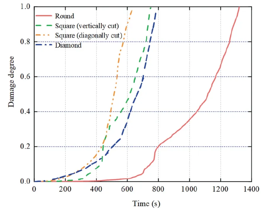
Fig.17.Relationships between damage degree and time.
Compared with other specimens,the round one has a greater axial displacement under the same damage degree (displacement loading).The damage degree curve develops gently first,then jumps and finally surges steeply,which suggests that its energy accumulation is more intense and crack generation requires greater energy in the early stage.The vertically cut square specimen also shares the same variation law of damage degree curve with the round one,but its energy accumulation and deformation resistance are weaker.The diagonally cut square and diamond specimens witness an approximately exponential increase in their damage degrees,demonstrating a weaker deformation resistance.
5.2.Analysis on damage evolution based on mechanical parameters
With the uniaxial compression damage of a specimen regarded as a continuously developing process,its stress-strain relationship conforms to the Weibull statistical distribution density function[41].Furthermore,by relating damage to defects contained in micro-elements,the damage degree of a specimen in the uniaxial compression process can be expressed as
whereDis the damage degree of the specimen;ε the axial strain;εpthe peak strain;andnthe shape parameter of Weibull distribution,can be expressed as
whereEdis the elastic modulus;and σpthe peak stress.
By substituting the test results of elastic modulus,peak stress and peak strain of different-shaped S-C combinations into Eq.(3),the damage model parameters and damage equations in the uniaxial compression process are derived (Table 3).The relationship between damage degree and axial strain is exhibited in Fig.18.It can be observed that the damage degree in the axial deformation process differs for different-shaped specimens.Similar to the damage curves based on AE parameters,the deformation resistances at a damage degree of larger than 0.2 follow the order:Square(diagonally cut),square (vertically cut),diamond and round.Such a result indicates that increasing the free area ratio to a certain extent(free area ratio smaller than 1.13)can improve the deformation resistance of S-C combination.In comparison to the round one,the other three specimens correspond to considerable damageaccumulation within small axial deformation and exhibit significant hardening characteristics.
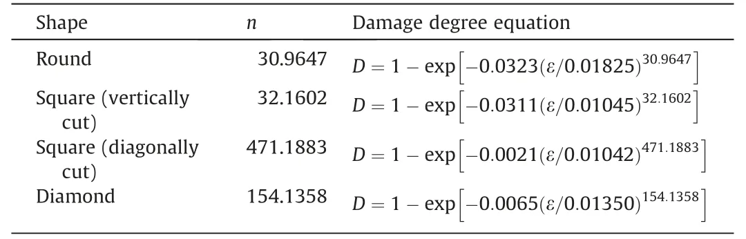
Table 3 Parameters and equations of damage degree model.
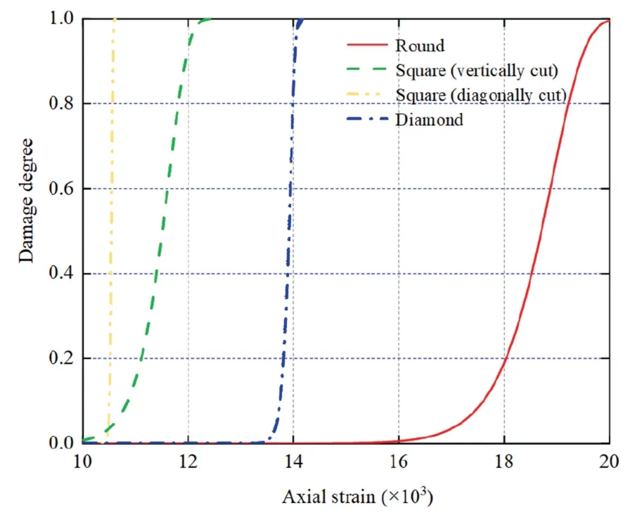
Fig.18.Relationships between damage degree and axial strain.
6.Conclusions
Based on the bearing structure of S-C combination in CDGB,four groups of different-shaped S-C combination specimens were produced.With this structure,the differences in mechanical characteristics and failure modes of S-C combinations with different free areas in the process of CDGB were explored,and the damage evolution model based on AE parameters and mechanical parameters was established.The main conclusions are as follows:
(1) The free area of S-C combination can be used as a quantitative index to evaluate the stability of the overburden control system.The compressive strength,peak axial strain and weakening modulus of combination specimens are negatively correlated with the free area.When the free area is the same,the increase in bonded area weakens the loadbearing capacity to some extent.
(2) The concept of the critical valuekfor the influence of free area on the deformation resistance of combination specimens was proposed and verified for the first time.Whenkis greater than 1.13,the deformation resistance of the specimen and the free area become negatively correlated,and the failure mode changes from tensile failure to shear failure.
(3) As the free area expands,the AE count gradually evolves from‘‘double peaks”to a‘‘single peak”.The expansion of free area shortens the energy accumulation and release time during loading;the micro cracks generated in the specimen change from a phased steep growth to a continuous increase,and the process in which micro cracks develop,converge,intersect and connect to form macro cracks accelerates.
(4) A damage evolution model was established according to AE evolution characteristics and mechanical parameters.With the aid of this model,the damage evolution processes of different-shaped S-C combination specimens were verified.
Acknowledgements
This work was financially supported by the National Natural Science Foundation of China (Nos.U21A20108,52322403,52174108,and 51974105),the Support Plan for Science&Technology Innovation Talents in Universities of Henan Province (No.21HASTIT024),the Scientific and technological innovation research team of Henan Polytechnic University (No.T2021-5),and the Henan Excellent Youth Science Foundation (No.222300420045).
- 矿业科学技术学报的其它文章
- Shear behaviours and roughness degeneration based on a quantified rock joint surface description
- Selective flotation of chalcopyrite from pyrite via seawater oxidation pretreatment
- Numerical modeling on strain energy evolution in rock system interaction with energy-absorbing prop and rock bolt
- Effect of particle gradation on pore structure and seepage law of solution in weathered crust elution-deposited rare earth ores
- Experimental study on instability mechanism and critical intensity of rainfall of high-steep rock slopes under unsaturated conditions
- Polysaccharides-based pyrite depressants for green flotation separation:An overview