A high-isolation coupled-fed building block for metal-rimmed 5G smartphones*
Aidi REN, Chengwei YU, Lixia YANG, Wei CUI, Zhixiang HUANG, Ying LIU
1Information Materials and Intelligent Sensing Laboratory of Anhui Province, Anhui University, Hefei 230601, China
2Aviation Key Laboratory of Science and Technology on Electromagnetic Environmental Effects, Shenyang 110000, China
3Science and Technology on Antenna and Microwave Laboratory, Xidian University, Xi’an 710071, China
†E-mail: renaidi@ahu.edu.cn
A dual-antenna building block with high isola‐tion is presented for metal-rimmed fifth-generation (5G)smartphones.A coupled-fed loop antenna and a coupledfed slot antenna based on a simple T-slot etched on the ground plane are meticulously designed to form a compact building block.Notably, although the coupledfed loop antenna and the coupled-fed slot antenna share the same aperture, a desirable isolation of >30 dB is exhibited.Afterward, an 8×8 multiple-input multipleoutput (MIMO) system is achieved by integrating four such dual-antenna building blocks.The measured mutual coupling and envelope correlation coefficients (ECCs)of the presented 8×8 MIMO system are <-18.5 dB and <0.02, respectively.
1 Introduction
Recently, MIMO technology has been extensively exploited in 5G terminals, as the channel capacity is proportional to the number of antennas (Hong, 2017).Nevertheless, due to the arrangement of many MIMO antennas operating in the same bands within a spacelimited smartphone, the interference between antennas is a fierce issue that suppresses the data rate.Further‐more, the more the elements placed, the more critical the interference.In consequence, alleviating mutual coupling and reducing the element size are crucial for a 5G MIMO system.
Various methods have been introduced to miti‐gate interference (Zhang XX et al., 2020).Amid these decoupling techniques, modifying ground planes, such as defected ground structure (DGS) (Hei et al., 2021)and etched slots (Jiang et al., 2019), have been used to mitigate mutual coupling.Besides, integrating addi‐tional structures, including a neutralization line (Guo et al., 2018), decoupling branches (Luo et al., 2022),and so on, can suppress interference effectively.Meta‐materials are also used to enhance isolation by reduc‐ing the coupling current (Sultan et al., 2020).To reduce the size of the decoupling structure, decoupling based on lumped elements has been investigated (Ye et al.,2022).The methods mentioned above need to intro‐duce external structures to enhance isolation, which takes up extra space.To simplify MIMO systems, anten‐nas with self-isolated characteristics have been stud‐ied (Ren ZY et al., 2019).Besides, polarization diver‐sity techniques (Li MY et al., 2016), characteristic mode theory (CMT) (Liu et al., 2019; Hu et al., 2022),stable null points (Zhao et al., 2018; Ren AD et al.,2019b), and elements with reduced grounding effect(Li YX et al., 2019) have been investigated.Further‐more, the requirement of further miniaturization has accelerated the investigation of multi-antenna pairs(Wong et al., 2017; Ren AD et al., 2019a; Sun et al.,2020; Chang et al., 2022; Hu et al., 2023).
The increased strength, durability, metallic luster,and stylish exterior have made the metal bezel attrac‐tive to customers.However, the existence of the metal bezel blocks the radiation of electromagnetic fields.Therefore, many researchers have been committed to the coexistence of MIMO systems with the metal bezel.Isolation of >13 dB is achieved by properly select‐ing the slot positions (Chen et al., 2019).An antenna pair composed of two tightly arranged open-slot anten‐nas has been presented, offering only an isolation of >10 dB by using a connecting line (Sun et al., 2021).The CMT has been used to find the desired modes and optimal feeding positions (Luomaniemi et al., 2021).As a result, a four-element MIMO system for 5G com‐munication with isolation >10 dB is obtained.The CMT is used to implement a MIMO system with a low specific absorption rate (SAR) and high isolation(>15.4 dB) for metal-rimmed smartphones (Zhang HH et al., 2022).However, only four elements are inte‐grated into a smartphone, which limits the improve‐ment of channel capacity.A dual-antenna building block based on a suspended metal strip is realized by selec‐tively exciting the half-wavelength and wavelength dipole-type mode, integrating only four elements (Qu and Piao, 2022).An eight-unit MIMO system was proposed for a full metal-framed tablet device.To mitigate mutual coupling, solution capacitance was used to suppress the traveling wave (12.94 dB) (Fang et al., 2022).
In this paper, a dual-antenna building block is designed, in which a coupled-fed loop antenna and a coupled-fed slot antenna occupy the same T-shaped slot.Note that the building block without integration of any external decoupling structure not only has a small size but also yields up to 30 dB of isolation.Then, a compact 8×8 MIMO system constructed by four dual-antenna building blocks for 5G metal bezel smartphone applications is designed and fabricated.Ultimately, measurement is conducted and the mea‐surement results are presented and discussed.
2 Compact MIMO array design
2.1 Coupled-fed dual-antenna module
2.1.1 Structure and performances of the proposed dual-antenna building block
Fig.1 is the structural diagram of the dual-antenna building block.As shown in Fig.1, the FR4 substrate with a relative dielectric constant of 4.4 is adopted as the system main board, and the specific size is 145 mm×75 mm×0.8 mm.The detailed structure of the dualantenna module is given in the dashed boxes in the figure.It can be observed that the structure is very simple, consisting of a T-shaped open slot engraved on the ground plane, a chip inductor (6.2 nH), and two L-shaped feed branches printed on the top surface of the system board.The inductor is placed at the open‐ing gap of the slot, and the thickness and height of the metal frame are 0.6 mm and 6.0 mm, respectively,with a 1-mm break at the opening gap.Clearances of 5 mm are retained on both sides of the system main board for placing components such as 2G, 3G, and 4G antennas.
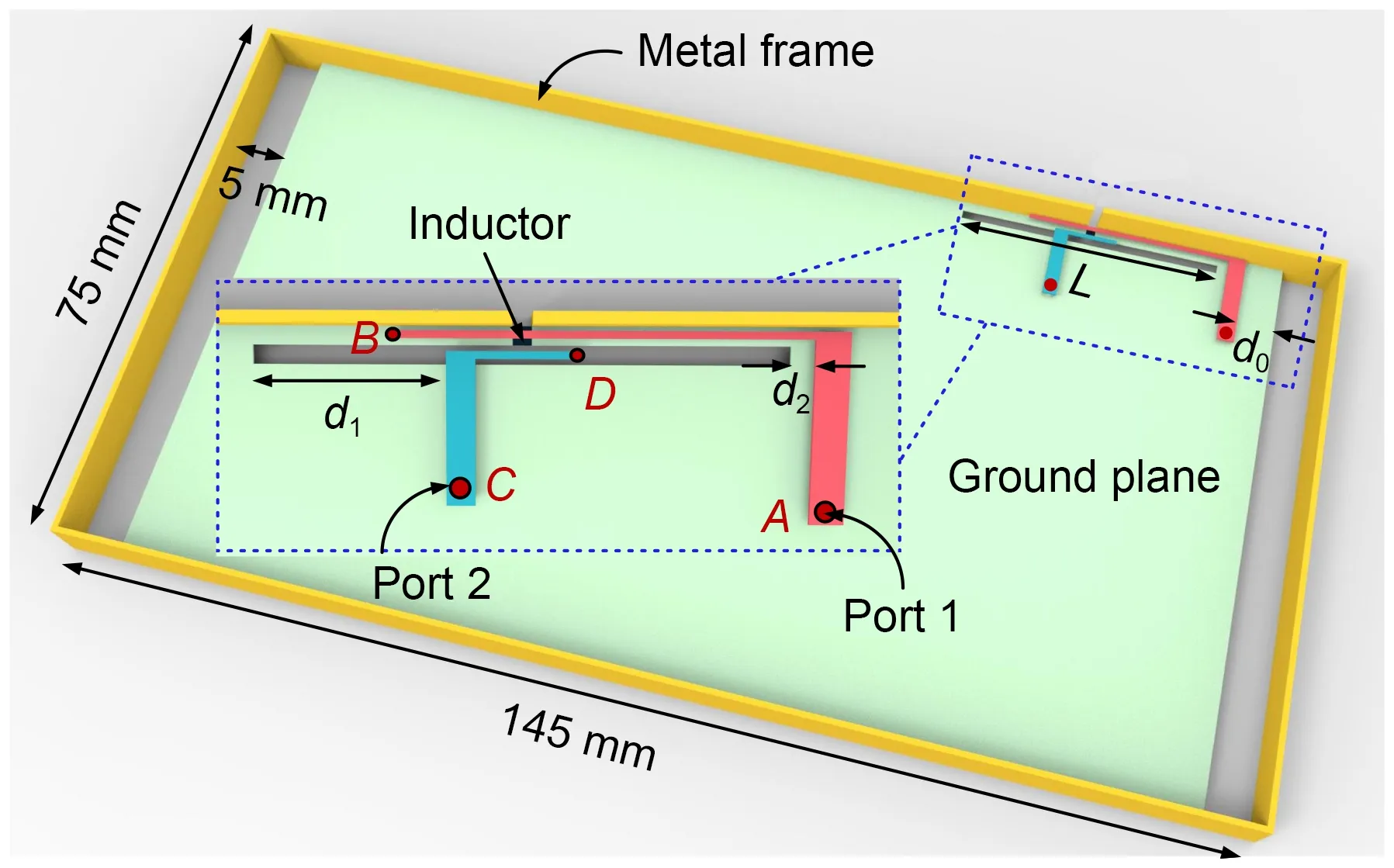
Fig.1 Structure of the compact building block (L=28.1 mm,d0=2.50 mm, d1=10.15 mm, d2=2.05 mm)
When the feed port of the coupled-fed loop an‐tenna (port 1) is fed, the surface current around the open slot is loop shaped, and the coupled-fed loop antenna (antenna 1) works at this time.The break on the metal frame can effectively improve the matching level of the coupled-fed loop antenna.The chip induc‐tor is also used to improve the impedance matching of the coupled-fed loop antenna.When the feed port of the coupled-fed slot antenna (port 2) is fed, the coupledfed slot antenna (antenna 2) works.The L-shaped coupled-fed branchABis composed of vertical and horizontal components; the size of the vertical part is 9.6 mm×1.8 mm, and the size of the horizontal part is 21.9 mm×0.4 mm.The L-shaped coupled-fed branchCDis composed of vertical and horizontal compo‐nents; the size of the vertical part is 7.6 mm×1.5 mm,and the size of the horizontal part is 5.25 mm×0.4 mm.The width of the designed compact building block is only 1 mm (0.012λat 3.50 GHz, withλbeing wave‐length), and the feeding structure is also very simple,which makes it easy to implement in engineering.
Fig.2 gives the simulatedS-parameter curves of the dual-antenna module.It can be seen from Fig.2 that the reflection coefficients of the two antennas in the 3.40–3.60 GHz frequency band are <-6 dB.It is noteworthy that the isolation between the two anten‐nas is >30 dB.Fig.3 gives the simulated ECC curve of the building block.It can be seen that the ECC of the two antennas is <0.02 in the entire working fre‐quency band.
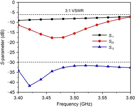
Fig.2 Simulated S-parameters for the dual-antenna module(VSWR: voltage standing wave ratio)
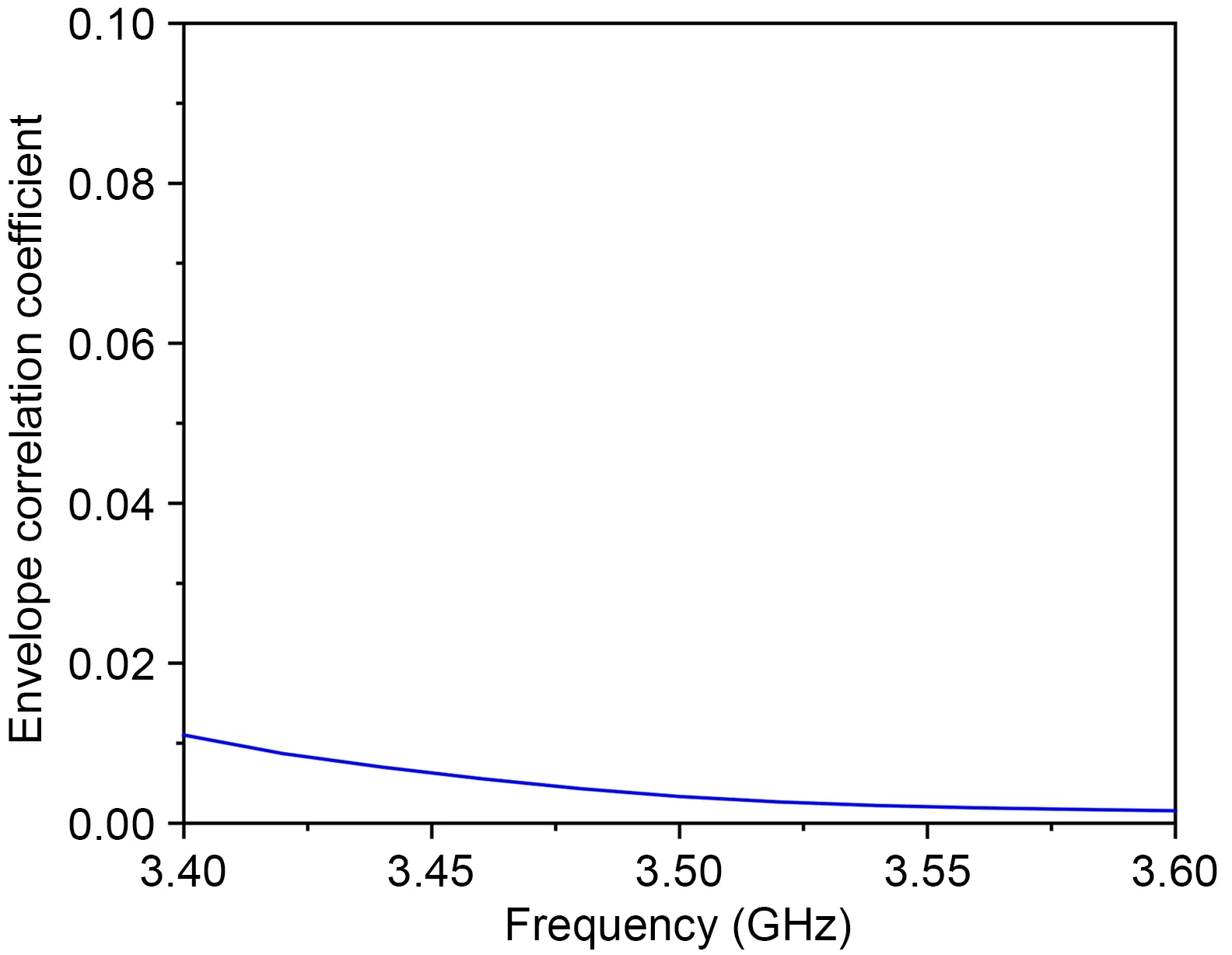
Fig.3 Simulated envelope correlation coefficient for the dual-antenna building block
2.1.2 Decoupling analysis
The decoupling mechanism of the proposed build‐ing block is investigated in Figs.4 and 5.The vector current distributions when the two antennas work sepa‐rately in the building block are shown in Fig.4.Accord‐ing to Fig.4a, when antenna 1 is working, the current on the ground plane flows mainly along the longer side of the ground, and the current distribution around the rectangular slot on the ground plane is a loop.According to Fig.4b, it can be seen that the current on the ground is mainly vertical to the longer side of the ground plane when antenna 2 is working.It can be concluded from Fig.4 that the ground currents induced by antennas 1 and 2 are almost orthogonal,reducing the coupling from the ground plane effec‐tively.The current distribution around the building block induced by the loop antenna and slot antenna is also orthogonal.
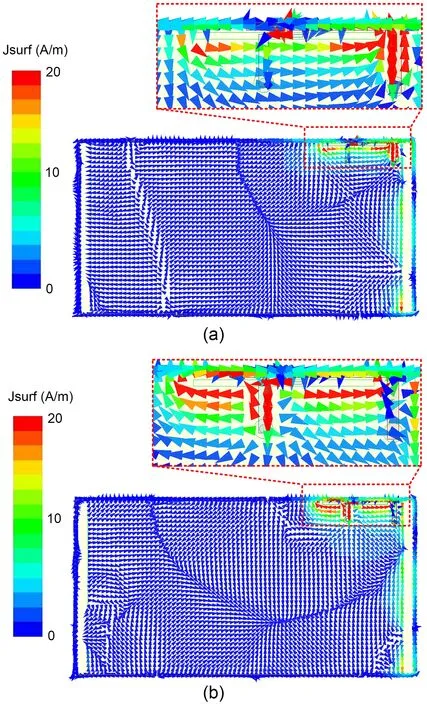
Fig.4 Simulated vector current distributions at 3.50 GHz when antenna 1 (a) or antenna 2 (b) is fed
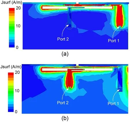
Fig.5 Simulated current amplitude distributions at 3.50 GHz when antenna 1 (a) or antenna 2 (b) is fed
Fig.5 gives the current amplitude distributions when antennas 1 and 2 work separately.As Fig.5a depicts, when antenna 1 works, port 1 is fed, and the current distribution around port 2 is very weak.From Fig.5b, it can be observed that during the operation of antenna 2, port 2 is excited, and the current distri‐bution at port 1 is very weak.Consequently, there are three reasons to explain the high isolation level for the proposed dual-antenna module:
1.Because ground currents induced by antennas 1 and 2 are orthogonal, the coupling from the ground plane is effectively mitigated.
2.The current distributions around the dualantenna module caused by antennas 1 and 2 are also orthogonal.
3.When the two antennas work separately, the current flowing into the other antenna feed port is very weak.
2.1.3 Parametric study
Since the two antennas in the designed dualantenna module occupy the same T-shaped open slot,the lengthLof the slot is a very important parameter,affecting the resonance frequencies of antennas 1 and 2 at the same time.
Fig.6 shows the simulatedS-parameter curves of the dual-antenna module whenLincreases from 27.9 to 28.3 mm with an interval of 0.2 mm.As shown in Fig.6a, asLincreases, the resonance frequency of antenna 1 shifts to a lower frequency.As observed from Fig.6b, whenLincreases from 27.9 to 28.3 mm,the resonance frequency of antenna 2 shifts to a lower frequency, from 3.50 to 3.45 GHz.Further observing Fig.6c, the isolation between the two units is the best whenLis 28.1 mm.Therefore, the final lengthLis selected to be 28.1 mm.
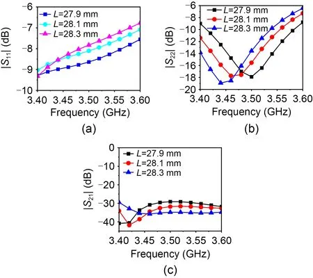
Fig.6 S-parameters of the building block with different lengths: (a) reflection coefficient of antenna 1; (b) reflection coefficient of antenna 2; (c) transmission coefficient (L:length of the slot)
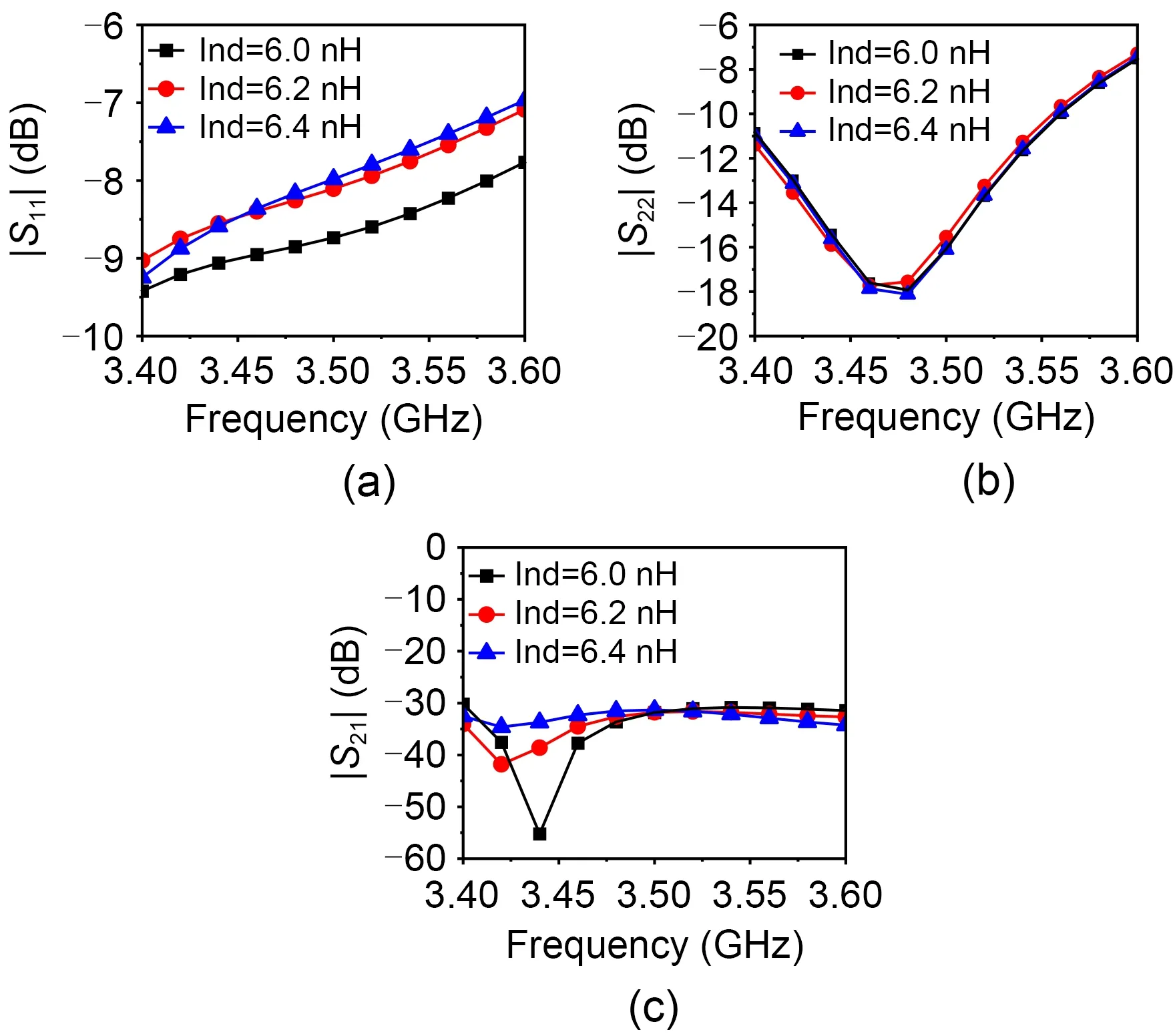
Fig.7 S-parameters of the building block with different inductance values: (a) reflection coefficient of antenna 1; (b)reflection coefficient of antenna 2; (c) transmission coeffi‐cient (Ind: inductance)
Fig.7 depicts the influence of inductance on the performance of the building block.Fig.7 shows that theS-parameter curves of the building block change when the inductance values are changed.As shown in Fig.7a, when the inductance value is increased from 6.0 to 6.4 nH, the resonance frequency of antenna 1 shifts toward a lower frequency.Observing Fig.7b,when the inductance value increases, the resonance frequency of antenna 2 almost remains unchanged.When the inductance value is 6.2 nH, the isolation between the two antennas is optimal, and the isola‐tion level is >30 dB.Therefore, the inductance value is finally selected as 6.2 nH.
2.2 Eight-element MIMO array antenna
2.2.1 Eight-element MIMO array structure and performances
An eight-element MIMO is implemented based on the coupled-fed dual-antenna building block.Fig.8 shows the detailed structure of the MIMO system.The 8×8 MIMO system has a symmetrical structure that is composed of four completely identical dualantenna modules.To improve the performance of the 8×8 MIMO array, the sizes of the two blocks are changed to some extent.
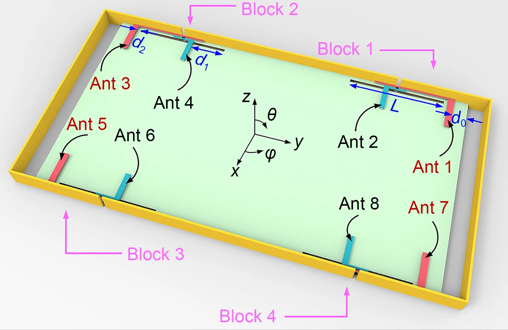
Fig.8 Configuration of the proposed eight-element MIMO system (L=28.1 mm, d0=5.10 mm, d1=9.55 mm, d2=1.65 mm)
The simulatedS-parameters of the proposed eightelement MIMO array are depicted in Fig.9.Due to the symmetry of the MIMO system, only part of the antenna performance is shown.According to Fig.9,the reflection coefficients of all elements are <-6 dB in the frequency band 3.40–3.60 GHz.Further observ‐ing Fig.9, due to the coupling between different mod‐ules and the changes in some parameters, the isolation of two antennas in the same building block is >29 dB,and the isolation of two elements between different modules (such as between antennas 1 and 7, between antennas 1 and 3, and so on) is >18.5 dB.The isola‐tions between antennas 1 and 7, and between antennas 1 and 3 in different modules are lower than the isolation in the same module.This phenomenon is reasonable because the polarizations of antennas 1 and 7 (anten‐nas 1 and 3, and so on) in different modules are the same.
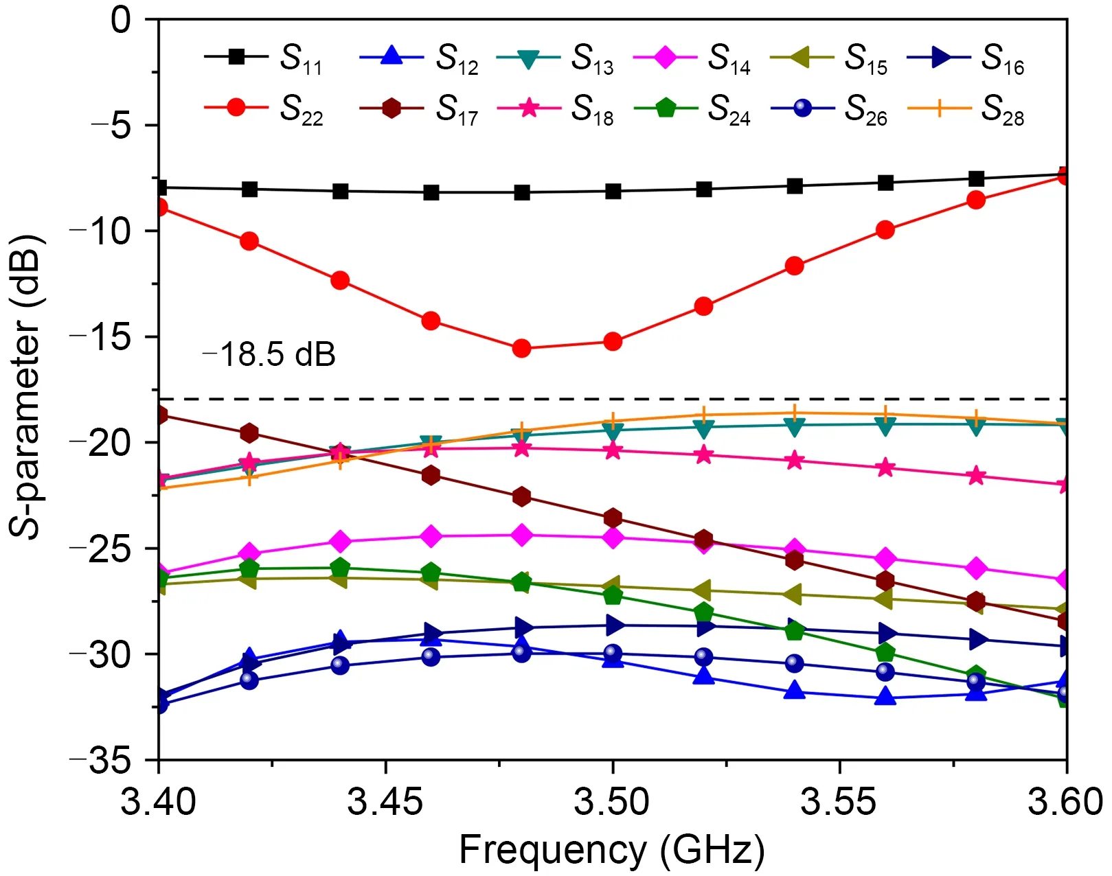
Fig.9 Simulated S-parameters of the eight-element MIMO system
2.2.2 Experimental results and discussion
To evaluate the performance of the designed eightelement MIMO system, we process and measure the MIMO array, and the physical diagram of the eightelement MIMO system is depicted in Fig.10.The top and bottom views of the physical eight-element MIMO array are presented in Figs.10a and 10b, respectively.
The measuredS-parameters of the eight-element MIMO array are presented in Fig.11.The reflection coef‐ficients for both antennas 1 and 2 are <-6 dB in the frequency band of 3.40–3.60 GHz, and the measured isolation of the whole MIMO system is >18.5 dB.Observing Figs.9 and 11, the simulatedS-parameters of the eight-element MIMO array agree very well with the measurement results.
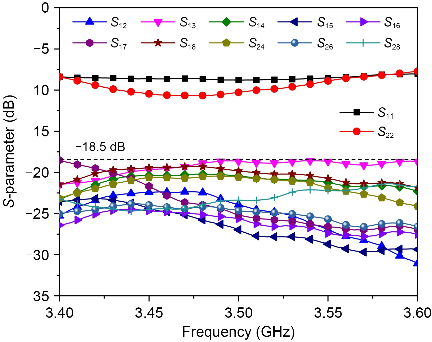
Fig.11 Measured S-parameters of the eight-element MIMO system
Fig.12 shows the measured efficiency of the MIMO system; the efficiency of the antenna varies from 43% to 54% over the entire frequency band, which fully meets the actual application requirements.
Fig.13 gives both the measured and simulated normalized radiation patterns for antennas 1 and 2 at 3.50 GHz.When one antenna is measured, the other ports match well to a 50-Ω matched load.It can be seen from Fig.13 that the measured patterns of the eight-element MIMO array are in good agreement with the simulated patterns.
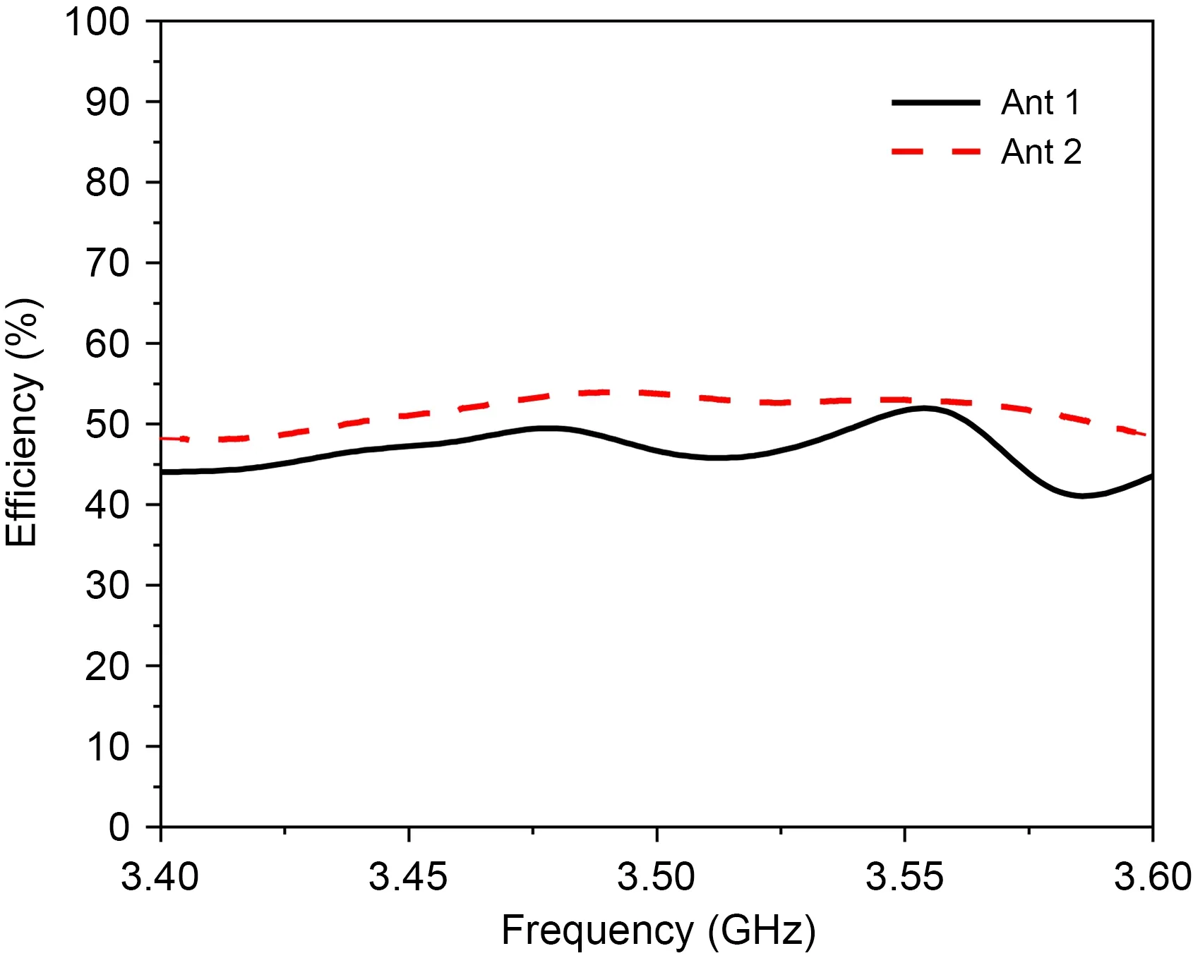
Fig.12 Measured radiation efficiencies
According to the measured three-dimensional (3D)radiation patterns, the ECCs are calculated and given in Fig.14.From Fig.14, the ECCs of the eight-element MIMO system are <0.02 in the entire working frequency band, which indicates that the designed eight-element MIMO array antenna has good MIMO performance.
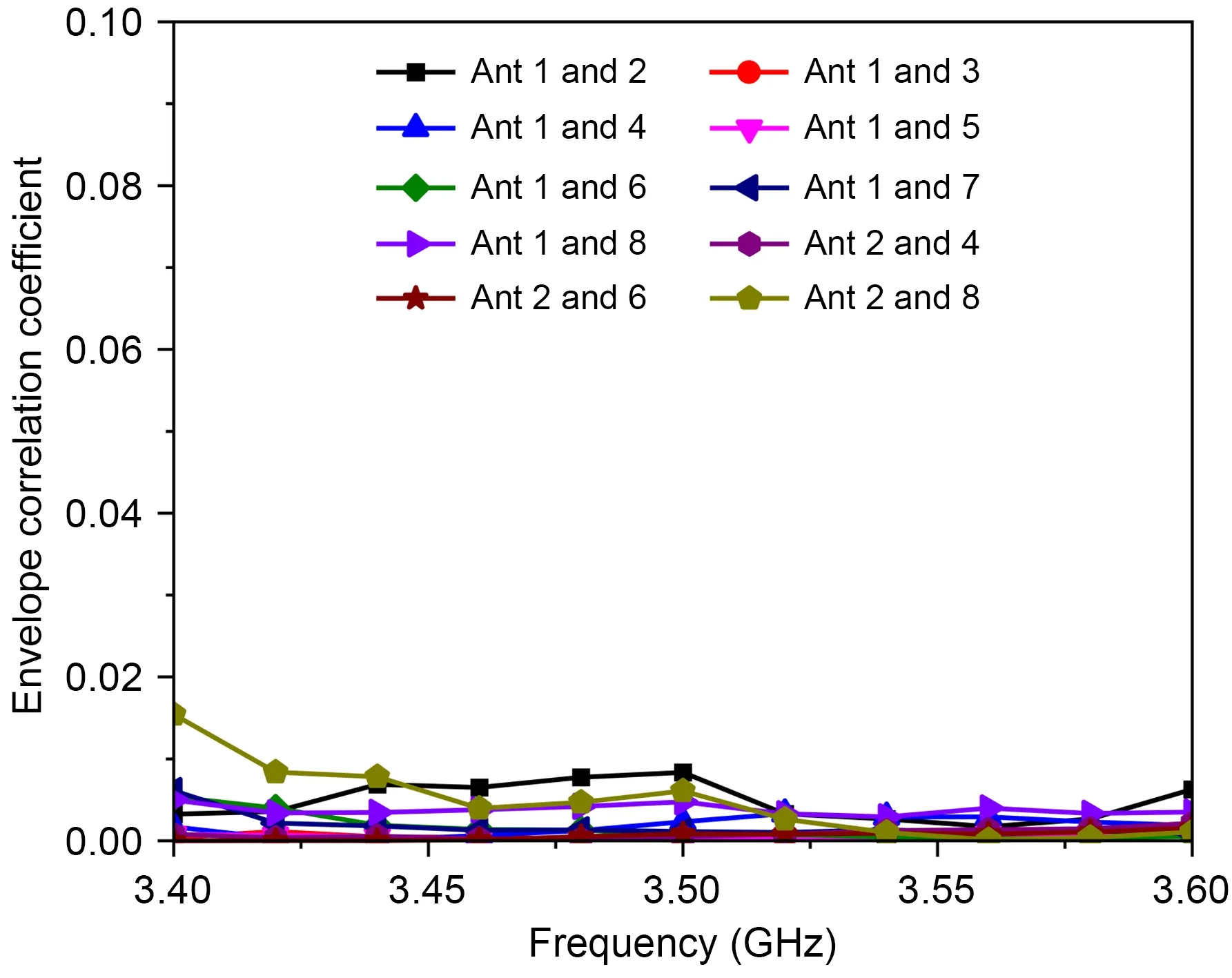
Fig.14 Measured envelope correlation coefficients for the eight-element MIMO system
The comparison between the referential designs and our study is presented in Table 1 to reveal the merits of our design.The size of the antenna pair provided by Hei et al.(2021) is far larger than that in this study.Moreover, these designs cannot be applied in smart‐phones with a metal frame (Hei et al., 2021; Ye et al.,2022).Ren AD et al.(2019a) proposed a MIMO sys‐tem with a metal frame.However, the isolation, ECC,and size of this study are better than those in the design presented by Ren AD et al.(2019a).Sun et al.(2021)provided a MIMO system with a wider band of 3.3–5.0 GHz.However, the isolation is only >10 dB, which is much lower than that (>18.5 dB) in this study.The elements in the MIMO systems proposed by Fang et al.(2022) and Zhang HH et al.(2022) are arranged sepa‐rately, which leads to a large size.Ultimately, the pres‐ent study provides good isolation, better ECC, and small size, simultaneously.
3 Conclusions
A compact coupled-fed dual-antenna building block has been constructed in this study.The build‐ing block is simple in structure and easy to process,and has a high degree of isolation.The dual-antenna building block is composed of a coupled-fed loop antenna and a coupled-fed slot antenna that completely overlap.Based on this dual-antenna module, an eightelement MIMO system is designed, and the fabricated eight-element MIMO array is measured.The measured isolation of the designed eight-element MIMO system is >18.5 dB without any decoupling element.In addi‐tion, the MIMO array has good measured efficiencies,with a measured efficiency variation range of 43%–54% in the entire working frequency band.The mea‐sured ECC of the MIMO system is <0.02.Therefore,the designed MIMO array has great potential in 5G metal-rimmed mobile phone applications.
Contributors
Aidi REN designed the research.Aidi REN and Chengwei YU processed the data.Chengwei YU drafted the paper.Lixia YANG, Wei CUI, and Zhixiang HUANG helped organize the paper.Aidi REN and Ying LIU revised and finalized the paper.
Compliance with ethics guidelines
Aidi REN, Chengwei YU, Lixia YANG, Wei CUI, Zhixiang HUANG, and Ying LIU declare that they have no conflict of interest.

Table 1 Comparison of the presented and referential antennas
Data availability
The data that support the findings of this study are available from the corresponding author upon reasonable request.
 Frontiers of Information Technology & Electronic Engineering2023年11期
- Frontiers of Information Technology & Electronic Engineering的其它文章
- Magnetically driven microrobots moving in a flow:a review*#
- Embedding expert demonstrations into clustering buffer for effective deep reinforcement learning*
- A hybrid-model optimization algorithm based on the Gaussian process and particle swarm optimization for mixed-variable CNN hyperparameter automatic search*
- Dynamic parameterized learning for unsupervised domain adaptation*
- High-emitter identification for heavy-duty vehicles by temporal optimization LSTM and an adaptive dynamic threshold*#
- Hybrid-driven Gaussian process online learning for highly maneuvering multi-target tracking*
