Preliminary estimation of rock-fall lateral dispersion by laboratory test
Louis Ngi Yuen Wong,Zhicheng Tng
a Department of Earth Sciences,The University of Hong Kong,Hong Kong,China
b Faculty of Engineering,China University of Geosciences,Wuhan,430074,China
Keywords:Rockfall Block shape Slope angle Oblique impact Lateral dispersion
ABSTRACT Lateral dispersion significantly directs the assessment of rockfall hazard and design of countermeasures.In the present study,the dependence of lateral dispersion on different controlling factors has been systematically evaluated by performing laboratory tests using three different rock block types,namely circular block,and two types of elliptical block.The three types of rock block are released onto an inclined surface with the identical initial status.Parallel,anti-parallel,and oblique impact tests set at slope angles of 22.5° and 45°are conducted to study the block-slope interaction of rockfall.Lateral dispersion of rockfall is less influenced by the block shape for the oblique impact,while the post-impact behaviors are greatly affected by the block shape.The key factors influencing the deviation of the post-impact trajectory direction are the slope angle (θ) and direction difference (Δφ).An empirical model is then developed to characterize the deviation distribution of lateral dispersion by 5th and 95th percentile values with the inclusion of the two key factors.Linear function can be used to describe the 5th percentile boundary,while hyperbolic function is good for the 95th percentile boundary,which need to be validated by field tests in the subsequent research.
1.Introduction
China is a country with frequent geological disasters(Huang and Li,2011;Yin,2011;Yin et al.,2016).Rockfall is a type of natural geohazard,which occurs rapidly and usually involves long travel distances.In Hong Kong and the western mountainous part of China,it is a recurring hazard and a number of rockfall incidents have been reported in recent years (Chau et al.,2003;Chai et al.,2015;Dong et al.,2019;He et al.,2019;Jiang et al.,2021;Zhang et al.,2021).Rockfall generally occurs on steep slopes such as coastal cliffs and rock walls in mountainous areas,which can be regarded as the fastest type of landslide driven by seismic or gravitational force,consisting of detachment,fall,rolling,sliding and bouncing of rock fragments(Ferrari et al.,2016).In many mountainous areas,rockfall has been a serious threat to human activities,infrastructures and transportation lines around the world due to the non-predictive trajectory with high kinetic/impact energy (Buzzi et al.,2013;Ferrero et al.,2016;Pappalardo,2018;Bostjančić and Pollak,2020;Nakajima et al.,2021).Rockfalls are also one of the hazards that may be associated with open pit mining,and the majority of rockfalls occur due to the unfavorable conditions of slopes,such as back break,fractures and joints (Oraee et al.,2016;Ruvin Wijesinghe and You,2016).For the motion of rockfall,the trajectory is dominated by the interaction of block-slope,which is mainly affected by the physical properties of rock block and slope,and the motion state of block(Labiouse and Heidenreich,2009;Li and Lan,2015;Pérez-Rey et al.,2019;Lanfranconi et al.,2020;Lu et al.,2021).Although a number of physical and numerical studies have been carried out in the past decades,mitigating rockfall hazard is still a challenging issue,owing to its complicated dynamics and of different nature from other types of landslides (Pei et al.,2019).
Modelling a falling rock block is extremely challenging because of the various possible modes of motion when the block travels down-slope,in addition to the irregular block shape.Most of the rockfall trajectory models use coefficient of restitution (CoR) for assessing the rebound of simulated block on the slope surface and a friction coefficient for rolling.A number of CoR definitions of rockfall are available in the literature,while no scientific consensus is reached about which one is the best to follow(Chau et al.,2002).The widely used definition in practice are the kinematic CoR,calculated by the ratio between magnitudes of bouncing and incoming velocities(Azzoni and de Freitas,1995;Chau et al.,2002;Asteriou and Tsiambaos,2016).In many cases,the kinematic CoR can be further decomposed into tangential and normal components with respect to the slope surface,which have been adopted in different studies(Evans and Hungr,1993;Budetta and Santo,1994;Chau et al.,2002;Asteriou and Tsiambaos,2016;Ji et al.,2019;Ye et al.,2019).Definitions associated with energies before and after impact are also available in the literature (Bozzolo and Pamini,1986;Evans and Hungr,1993;Chau et al.,2002;Bourrier et al.,2009;Asteriou and Tsiambaos,2016),in which both translational energy and total energy are used to determine the values of CoR,respectively.In addition,the relation between CoR and several physical quantities is developed by Asteriou and Tsiambaos(2018),including incident normal momentum,impact velocity,block mass and hardness.Normally,the CoRs distribute in the range between 0 and 1(Azzoni and de Freitas,1995;Chau et al.,2002;Labiouse and Heidenreich,2009;Spadari et al.,2012;Asteriou and Tsiambaos,2018;Ye et al.,2019).Based on the field/laboratory experiments,both normal and tangential restitution coefficients can be greater than one (Paronuzzi 2008;Spadari et al.,2012;Ji et al.,2019).On the basis of laboratory investigations,Buzzi et al.(2011)and Ji et al.(2019) further concluded that the mechanism leading to high values could be attributed to the combination of impacting angle,rotational energy and block angularity.Although there exist several limitations for the definitions of CoR(Ye et al.,2019),this parameter has been widely used in practice and academia.
Due to the difficulty in capturing the actual trajectory in threedimensional(3D)space,the lateral dispersion in 3D space is usually ignored.The lateral dispersion is initially defined by Azzoni and de Freitas (1995),calculated by the ratio between the distance (D)separating the two extreme fall paths and the length of the slope(L),as shown in Fig.1.Crosta and Agliardi(2004)further indicated that the slope geometry,the local roughness of slope and the material properties are the key factors influencing the lateral dispersion of rockfall.According to the field experiments by Azzoni and de Freitas (1995),the lateral dispersion of rockfall commonly distributes in the range of 10%-20%,regardless of slope length.Numerical simulations using geometrically complex slopes by Agliardi and Crosta (2003) illustrated that the lateral dispersion can be up to 34%.Dorren et al.(2005,2006) performed field tests on forested slopes and the deviation was assessed by direction and distance between subsequent impacts on the basis of traces.Bourrier et al.(2009) further established an empirical probabilistic model with the inclusion of lateral dispersion based on the data provided by Dorren et al.(2005),in which the lateral dispersion was defined by slope aspect and pre-impact trajectory.Recently,Asteriou and Tsiambaos (2016) reconsidered the lateral dispersion of cubic blocks as the dihedral angle between the pre-impact and postimpact planes that contain the trajectory in 3D space (labeled as deviation angle Δein the reference,as shown in Fig.2).One of limitations of the study is that the influence of block shape on the lateral dispersion is ignored.In the literature on the lateral dispersion of rockfall,there are few laboratory tests studying the effects of rock blocks of different geometrical shapes.The present study involves rockfall test using three different geometries of rock block (one circular and two elliptical blocks),which is mainly designed to study the effect of geometrical shape of rock block on the lateral dispersion after impact on the rock plane.An empirical lateral dispersion model is developed based on the experimental observations,which can be used to estimate the deviation of the post-impact trajectory as a function of direction difference(Δφ)and slope angle (θ).
2.Laboratory investigation
2.1.Experimental setup
The present experimental setup comprises different components,namely rock blocks with different geometries to represent falling blocks,an impact surface to represent the natural ground,a block release mechanism and a recording system.The three types of rock block are fabricated by water abrasive jet cutting,which can ensure that the geometrical shape of each type of rock block is identical to a great extent.The blocks are spray-painted on one side before testing to allow a clear identification of the target points at the centroid.Camera 1 is a typical digital camera to capture the deviation angle Δeafter impact.Camera 2 is a high-speed video camera to continuously capture the block motion before and after impact.The impact surface and blocks are made of Carrara marble.Detailed information about the high-speed video camera usage and the rock is provided by Wong and Einstein(2009).A simple release mechanism involving an inclined tube with adjustable height and inclination is designed(Fig.3),so as to control the incident velocity of the rock block.The real geometry of rock slope is irregular,and the slope is high,which can hardly be duplicated in the small-scale laboratory test.There is a suite of small-scale experimental investigations of rockfall in the literature.All these studies involved simplified geometry of slope and falling block.
The major-axis of the rock block was set to be perpendicular to the horizontal plane at the beginning (i.e.the two sides of the cylindrical rock blocks are parallel to the axis of the tube),which was allowed to move downslope along the tube under gravity.The right angle between major-axis of block and horizontal plane is controlled by combination square,and the centroid positions of blocks at the initial state are the same.A grid paper(1 mm square)is pasted on the vertical slab as the background for location reference to facilitate the subsequent calculation of velocity of the blocks before and after impact.One circular and two elliptical blocks of different dimensions are used(Fig.4).The diameter of the circular block (type I) is 40 mm.The semi-major axis for the elliptical blocks is 40 mm;while their semi-minor axes are 30 mm(type II)and 20 mm(type III),respectively.Using rock blocks with different shapes and dimensions make the study of the influence of oblateness possible,which is the ratio of difference between the major and the minor axes of elliptical block to its major axis.The micro-fractures induced by the repeated impact between block and plane,if any,are not assessed and considered in this study,which may cause bias to the analysis of experimental results to some extent.
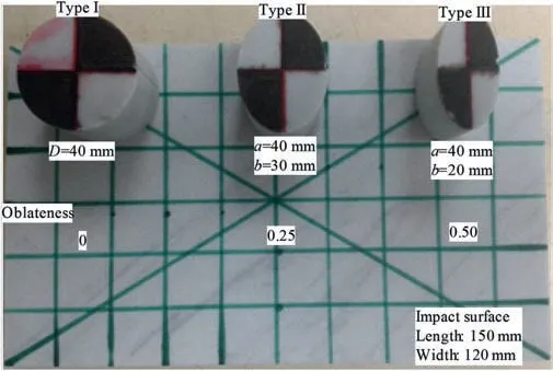
Fig.4.Block type and impact surface.

Fig.5.Impact type of rockfall.
2.2.Experimental method
Slope angle (θ) is set at 0°,22.5°or 45°,respectively.In field situation,oblique impact is common,which means that the travelling direction of the block may not be along the dip direction of the impact surface(Δφ≠0)and the post-impact direction usually deviates from the pre-impact direction(labeled as deviation angle,Δe),as shown in Figs.2 and 5.The direction difference is set at 0°,45°,90°,135°and 180°,respectively.For comparison,several coplanar impact tests are also conducted,which means that the travelling direction of the block is parallel to the dip direction of the impact surface (Δφ=0).Thirty-three sets of tests are performed,and each set of tests is repeated 20 times.Table 1 lists the sets of tests and summarizes the averaged test results.A MATLAB program is written for determining the position and speed of a series of target points,by analyzing the sequences of photographs.With a known photographic frame rate,the velocity can be determined from the distance covered by the centroid of the block over a given number of frames.In the present study,five frames before impact and ten frames after impact have been used for each velocity calculation.Image distortion has not been taken into account in the measurement,which may cause some errors.
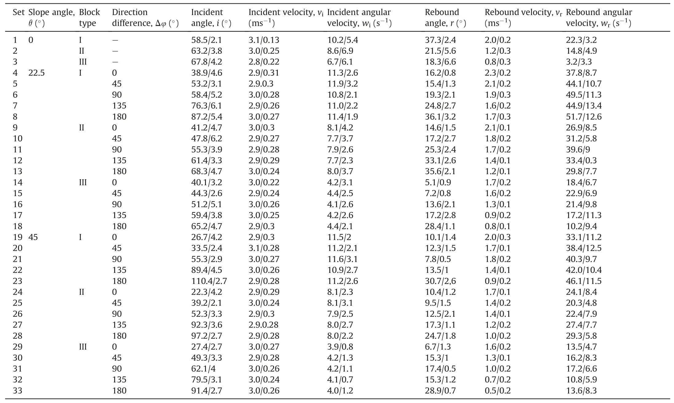
Table 1Experimental programme: incident and rebound characteristics (mean value/standard deviation).
3.Results and evaluation
3.1.Influences of block shape
Fig.6 presents the trend ofnCoRas a function of rebound angles,andnCoRis calculated by the ratio between rebound and incident velocities of its normal component,respectively.The mean values ofnCoRfor the three block types are also given in the figure to the right of the respective dashed lines.For type I,the values are concentrated over a relatively narrow range,while with the increase of oblateness,the change of rebound angle is more evident.It is clear that with the increase of rebound angle,nCoRincreases and the relationship of the two variables could be roughly fitted by a linear function.
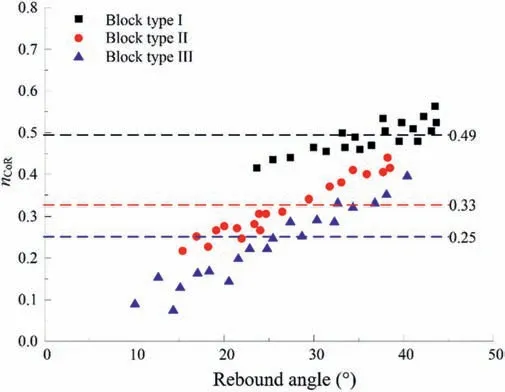
Fig.6.nCoR versus rebound angle for the three block types impacting a horizontal surface.
Fig.7 presents the effect of block shape on the deviation angle(Δe) of post-impact trajectory of the three block types on a horizontal plane.The radial axis represents the rebound angle and the circumferential axis represents the deviation angle (Δe).It is evident that with the increase of oblateness,the deviation angle(Δe) becomes greater.However,all the deviation angles are scattered in a certain range (type I exhibiting deviations from -13°to+18°,type II exhibiting deviations from-21°to+25°,and type III exhibiting deviations from-41°to +38°).
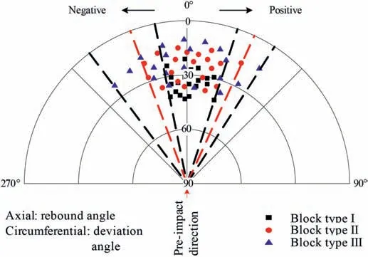
Fig.7.Polar plot of deviation angle versus rebound angle for the three block types impacting a horizontal surface.
A summary histogram of all measured deviation angle of postimpact trajectory of the three block types is shown in Fig.8.The above summary plots and statistical distributions could provide insights for a preliminary empirical evaluation of the potential hazard dimensions with respect to protective structure design associated with desired probability levels.The deviation of the block from its pre-impact trajectory at the contact point affects its subsequent trajectory.

Fig.8.Histograms of lateral dispersion for the three block types impacting a horizontal surface.
3.2.Influences of slope angle for parallel and anti-parallel impacts
In the present study,the slope angles of parallel and antiparallel impact surfaces were set at 22.5°and 45°to assess the influences of slope angle on the rockfall behaviors.In the case of antiparallel impact tests,the slope angle is negative (Fig.5),which resembles a rockfall protection embankment in practice.Slip and rotation around contact point were observed for block types II and III,especially for parallel tests with inclination of 45°,resulting in longer contact duration.The extended contact time leads to higher energy loss,which would be a plausible reason for the lower correspondingnCoR.
Fig.9 plots thenCoRagainst the rebound angles for parallel impact tests.The maximum rebound angle is about 25°for parallel impact tests with the slope angle of 22.5°,except type III (about 35°).However,the maximum rebound angle is about 20°for the case of the slope angle of 45°for the three block types.In addition,the average values ofnCoRof the three block types only differ slightly for the two slope angles.This phenomenon is different from the previous studies conducted by Chau et al.(2002),who concluded that the mean value ofnCoRincreases as the slope steepens.It is clear that rebound angles are concentrated over a narrow range for block type I.Zero rebound angle was also observed in the case of 45°slope angle for block type III,which means that the block slipped along the inclined surface.
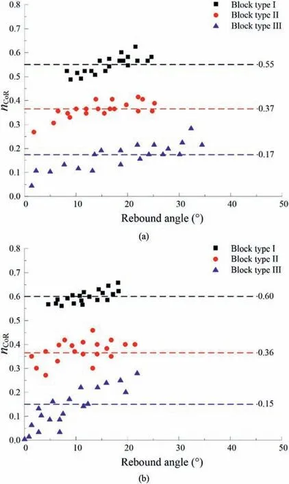
Fig.9.nCoR versus rebound angle for the three block types impacting an inclined surface with different slope angles: (a) 22.5° and (b) 45°.
Additionally,block shape affects the deviation of the postimpact trajectory,as shown in Fig.10.With the increase of oblateness,there is an increasing deviation(type III has the greatest deviation).However,all the deviations are scattered in a certain range.For type I,the deviations scatter from-6°to+6°for the two slope angles;for type II,they range from-16°to+11°for the two slope angles;for type III,the deviations scatter from-20°to+22°for the slope angle of 22.5°,and from -18°to +17°for the slope angle of 45°.The above distribution analysis reveals that the dispersion is a crucial parameter that should be considered in the design of mitigation measures.
In the case of anti-parallel impacts,the slope angle is“negative”,forming a barrier.The responses of the three type blocks impacting the two inclined surfaces observed in our experiments are presented in the rose diagrams in Fig.11.The pre-impact direction is pointing from 180°to 0°(as described in Fig.5,and also indicated by the red arrow in each rose diagram).Both the block shape and the slope angle significantly affect the post-impact trajectory.For the slope angle of -22.5°,the predominant post-impact direction was dictated by the pre-impact direction for type I (deflecting backwards only three times),whereas all blocks were deflected backwards for type III.However,it seems that the post-impact trajectories of the blocks are less consistent and any direction was possible for type II.For the slope angle of -45°,all the three type blocks were deflected backwards.The backwards deviation becomes greater with the increase of oblateness of the three block types.Thus,we can infer that with the increase of slope angle,the effect of block shape on the anti-parallel impact behavior decreases.
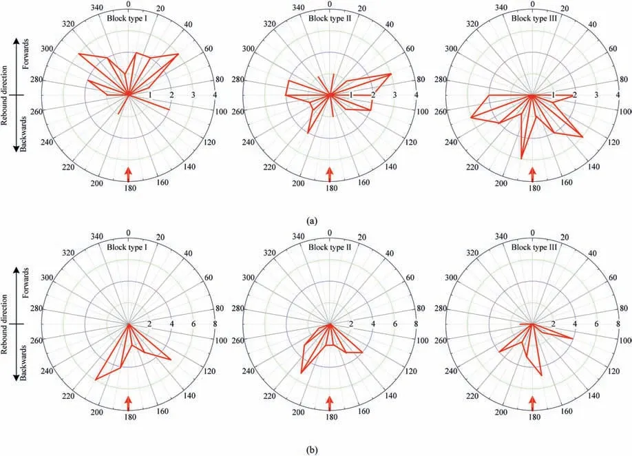
Fig.11.Rose diagrams of the post-impact trajectory direction for the three block types impacting an anti-parallel inclined surface (statistical interval is 20°) with different slope angles: (a) -22.5° and (b) -45°.
3.3.Influences of slope aspect and dip on oblique impacts
In reality,the angle between the strike of impact surface and the pre-impact direction of block trajectory is not orthogonal,leading to an oblique impact.Thus,the impact surface will guide the block in a specific direction.Due to the complex geometry of block and oblique impact,it is impossible to accurately predict the postimpact direction of block trajectory.To study the effect of slope aspect and dip on oblique impact,an experimental procedure was developed and implemented in the present study.The impact surface was set to two slope angles of either 22.5°or 45°and was then rotated clockwise 45°,90°and 135°with respect to the slope aspect (Δφ≈45°,90°or 135°,respectively).As such,several possible combinations between the pre-impact trajectory and the slope aspect were considered in the tests.For each test configuration,20 repeated tests were performed and the results were listed in Table 1.In the present study,the block pre-impact directions of individual test configurations are not the same due to the sliding of the released block on a relatively long distance along the tube,which results in slightly varied incident configurations.
Fig.12 presents all the results in terms of direction difference(Δφ) and deviation angle (Δe).It is apparent that the direction difference,the slope angle and the block shape affect the deviation.As the direction difference increases towards an anti-parallel impact,the deviation increases.The effect of block shape seems more obvious for the case of 45°inclination (as shown in a wider deviation) and both the lower and the upper bounds of deviation for the three type blocks are greater than those of the slope angle of 22.5°.For the same direction difference and slope angle,the deviation range increases with the decrease of oblateness,indicating that the post-impact behavior of block with lower oblateness is relatively more consistent and less random.However,the main factors influencing the deviation are the slope angle and the direction difference according to the present experimental results.
4.Lateral dispersion model
In this section,an empirical model considering block lateral dispersion for oblique impact is proposed based on the present extensive experimental results.As shown in Fig.12,it is unreasonable to simply adopt the mean values of deviation to describe the post-impact direction.Thus,percentiles,commonly used in statistical analysis,are adopted because the distribution of deviation amongst all the test sets cannot be described by the mean value or a general function.The 5th and 95th percentile values,denoted bye5%ande95%,respectively,are used.Several simple functions,such as linear,power,logarithmic,exponential and hyperbolic curve fitting approximations were used to fit the experimental results.Fig.13 shows that for the two slope angles,the 5th percentile boundary can be best represented by a linear function and the 95th percentile boundary by a hyperbolic function.To determine the specific form of the two models,the raw data set was subjected to least squares regression analysis.Another exercised principle was to minimize the number of fitting coefficients.Finally,two simple functions were selected with inclusion of the slope angle,leading to Eqs.(1) and (2) for the 5th percentile and 95th percentile boundaries,respectively:
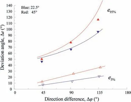
Fig.13.Percentile deviation model for lateral dispersion.
Although cubic rock block is used by Asteriou and Tsiambaos(2016),totally different from circular and elliptical blocks used in this study,the lateral dispersion after oblique impact is mainly affected by the same factors (i.e.slope angle,and direction difference).It should be noted that the block shape greatly affects the post-impact behavior,which can partly be illustrated by Figs.6-11,as also emphasized by Asteriou and Tsiambaos (2016).The empirically derived model could be used to estimate the deviation of impacts on rock slopes to some extent,while experimental data from real rockfall events and larger-scale tests are necessary for further validating of the developed empirical lateral dispersion model.
The authors believe that field tests are of crucial importance and practical value for the evaluation of the highly random rockfall phenomenon,such as the lateral dispersion investigated here.However,their high costs and complex logistic issues often do not allow their extensive use and,up to date,very few field test data are available for the statistical analysis.The present laboratory study can provide some key insights to further understand the behavior of rockfall and its lateral dispersion.The derived formulas would be useful in planning field scale rockfall tests and the associated threedimensional simulation modeling analysis.
5.Conclusions
The dynamics and trajectories of falling rock blocks are greatly influenced by the block shape and the slope geometry.The effect of block shape is first evaluated by performing tests on horizontal impact surface.With the increase of block oblateness,we observe that: (i) the averaged value ofnCoRdecreases;(ii) a linear function can be used to correlate the relationship betweennCoRand the rebound angle;and (iii) the deviation of post-impact trajectory of the three type blocks becomes greater,but scattered in a certain range.For parallel impact tests,deviation angles increase as the oblateness increases.For anti-parallel impact tests,both the block shape and the slope angle significantly affect the post-impact trajectory.With the increase of slope angle,the effect of block shape on the anti-parallel impact behavior decreases.For oblique impact tests,block with lower oblateness generally leads to a consistent post-impact behavior,and an empirical statistical model is proposed to evaluate the trajectory lateral dispersion direction.
Declaration of competing interest
The authors declare that they have no known competing financial interests or personal relationships that could have appeared to influence the work reported in this paper.
Acknowledgments
The first author acknowledges the support from the Start-up funding and Seed Funding Programme for Basic Research for New Staff at the University of Hong Kong.The second author acknowledges the support from the Natural Science Foundation of China(Grant Nos.42177165 and 41672302),and the Opening fund of State Key Laboratory of Geohazard Prevention and Geoenvironment Protection (Chengdu University of Technology) (Grant No.SKLGP2018K018).
 Journal of Rock Mechanics and Geotechnical Engineering2023年12期
- Journal of Rock Mechanics and Geotechnical Engineering的其它文章
- The formation of orthogonal joint systems and cuboidal blocks: New insights gained from flat-lying limestone beds in the region of Havre-Saint-Pierre (Quebec,Canada)
- Numerical analysis of the effects of vesicle distribution characteristics on the engineering properties of volcanic rocks
- A hybrid attention deep learning network for refined segmentation of cracks from shield tunnel lining images
- 3D limit analysis of rock slopes based on equivalent linear failure criterion with tension cut-off
- Mutual impact of true triaxial stress,borehole orientation and bedding inclination on laboratory hydraulic fracturing of Lushan shale
- Unloading-induced permeability recovery in rock fractures
