3D limit analysis of rock slopes based on equivalent linear failure criterion with tension cut-off
Zhibin Sun,Bowen Wng,Yongxin Li,Jingshu Xu,Jin Ji
a School of Automotive and Transportation Engineering,Hefei University of Technology,Hefei,230009,China
b Key Laboratory of Ministry of Education for Geomechanics and Embankment Engineering,Hohai University,Nanjing,210024,China
c College of Architecture and Civil Engineering,Beijing University of Technology,Beijing,100124,China
Keywords:Rock slope Hoek-Brown criterion Stability analysis Tensile strength Limit analysis
ABSTRACT Hoek-Brown (HB)failure criterion is widely used to predict the strength of intact or heavily jointed rock mass.For stability analysis of rock slopes governed by the HB failure criterion,the equivalent linearity to Mohr-Coulomb (MC) criterion is often adopted,leading to the well-known equivalent Mohr-Coulomb method (EMCM).Existing studies on EMCM analysis mainly consider the shear strength of rock material,while consideration of the tensile strength is rare.This contradicts the fact that the underlying tensile strength of rock mass has considerable impact on the rock slope stability in real world.In this regard,this paper proposes a limit analysis-based approach that can account for tension in the threedimensional (3D) stability analysis of HB rock slope.This approach is established on the equivalent linearity of the HB criterion with consideration of tensile strength,known as the equivalent tension cutoff MC method (ETMCM),and using a horn-like 3D mechanism of limit analysis.The safety factor solutions given by the proposed approach are validated by previous studies and numerical results.Parametric studies are conducted to investigate the effect of rock tensile strength on slope stability.Results show that the consideration of tension leads to a more conservative safety factor and a sharper curvature of the failure surface,and these impacts tend to be more obvious with the increases in slope inclination and slope width.Finally,the stability of the HB rock slope under seepage conditions is studied using the proposed approach.The results indicate that the effect of tensile strength is highly remarkable in seepage circumstances.
1.Introduction
Rock mass is usually considered as an anisotropic material since its strength characteristic is influenced by certain circumstances,such as faults,joints,fractures,and weak interlayers.However,rock mass can still be regarded as homogeneous and isotropic when it is intact or only contains uniformly distributed small joints.For these types of rock mass,it is generally accepted that the failure strength is highly nonlinear and cannot be accurately represented by the linear Mohr-Coulomb (MC) failure criterion.Correspondingly,the Hoek-Brown(HB)failure criterion gives a sound description of the strength of homogeneous rock mass,either intact or fractured types (Hoek,1983;Eberhard,2012).To date,the HB criterion has been widely used in various rock engineering,such as dams,slopes and tunnels.
Stability assessment is essential in safety evaluations or designs of rock slopes under the HB criterion.Many efforts have been contributed to the stability analysis of the HB rock slope.Yang et al.(2004)employed the generalized tangential technique to compute the rigorous upper bounds of stability factors of homogeneous rock slopes.Li et al.(2008)produced stability charts for rock slopes with limit analysis method using equivalent MC parameters.The effects of rock mass disturbance on HB rock slope stability were also discussed using finite element limit analyses(Li et al.,2011).The above stability analyses were mostly carried out under two-dimensional(2D) conditions.Recently,increasing attention has been paid to three-dimensional (3D) stability analysis of HB rock slopes.This is because the 2D analysis is not suitable for rock slopes that are mostly restrained in width,for instance,due to adjacent rigid formation or manual excavation.In that scenario,2D analysis produces an overly conservative stability solution and overestimates the true strength of rock mass when performing backanalysis from a known failure case.Yang and Long (2015) presented a 3D mechanism for the stability of rock slope under the HB criterion.With this mechanism,Xu and Yang (2018) further provided a series of stability charts of 3D HB slopes.Li and Yang(2018)analyzed the seismic displacement analysis of 3D rock slopes with the combination of the kinematic limit analysis and the Newmark method.Wang et al.(2021) conducted a 3D upper-bound analysis of rock slopes under steady state hydraulic conditions.
The aforementioned literature on 2D and 3D analyses of HB slope assumed that the slope failure is completely controlled by the shear strength of rock mass,while consideration of the tensile strength and tension cut-off was rare.This is contradictory to the fact that rock often has considerable limited tensile strength,varying from serval MPa to dozens MPa (Coviello et al.,2005;Li et al.,2020),as well as the experimental observation that both shear and tensile fractures appear when shear loads are applied on rock specimens(Cresswell and Barton,2003).In fact,there is little interest in considering rock tension in the early development of the HB criterion,because the stability of small rock slopes and shallow tunnels,which are often encountered at that time,is mainly controlled by shear strength/failure.However,with the emergence of complex rock geo-structure,there is a growing awareness to consider tensile strength when using the HB failure criterion.Guo et al.(2017) conducted a FLAC3D simulation to show that tensile failure has a relatively great effect on the stability of jointed rock slope.The latest 2018 edition of the HB criterion takes into account the tensile strength of rock mass (Hoek and Brown,2019).Alternatively,the elasto-perfect plastic constitutive model (J-Hoek model) was proposed by Ismael and Konietzky (2019) to account for the simplified flow rule for both tensile and compressive region.
The above-mentioned considerations of tensile strength associated with the HB criterion are in terms of criterion modifications and numerical simulations.However,it is still necessary to present a theoretical approach to capture the tensile strength in stability estimation of the HB rock slope.This is because numerical simulations suffer from a heavy computational burden in the primary design or reliability analysis of rock slopes due to the model construction,meshing and calculations,while analytical methods are preferable in these scenarios since the computational time is significantly reduced with the guarantee of the results accuracy.For the width-constrained slope,the necessity of a convenient theoretical approach is greater,as numerical simulations need more meshes and computational costs in 3D analysis.This motivates this paper to present a theoretical approach that can consider the tensile strength of rock mass in the 3D stability analysis of HB rock slopes.
There are two recommended approaches if the tensile stress is considered in slope analyses,i.e.the introduction of a tension crack or adjustment of the failure envelope to eliminate or reduce tension(tension cut-off) (Duncan and Wright,2005).Though the former approach is an earlier and more common strategy,the latter method will be implemented in this paper.The merits of doing this can be found in the literature (Baker,1981;Kaniraj and Abdullah,1993;Utili,2013;He et al.,2019) and summarized below.
(1) Tension cut-off is a consideration on the material model,rather than tension crack that assumes the geometry of failure mechanism.This is more useful to avoid a presumption of the value boundary of slope sliding.
(2) The location and depth of the presumed tension crack are independent of the true tensile strength of the geo-material.This means that the tension crack strategy does not realistically capture the effect of tensile strength.Yet tension cutoff can deal with the tensile strength value associated with the HB strength parameters,or that reported by tension test of the rock mass.
(3) Tension crack strategy uses a discontinuous sliding surface that combines a straight line and a curve,while tension cutoff ensures the continuity and smoothness of the whole sliding surface.Tension cut-off also allows a large separation velocity in the kinematic admissible mechanism,which is consistent with the observation in practice where a larger deformation occurs in the head region of a landslide (Park and Michalowski,2017;Ji et al.,2021).
With the tension cut-off strategy,an equivalent tension cut-off MC method (ETMCM) is proposed to account for the tensile strength using the HB criterion.The ETMCM is based on the tension adjustment of equivalent linear MC envelope of HB criterion,of which the details will be described in the following section.Apart from the strategy of considering tension,the adoption of proper stability analysis approach is of importance as well.The commonly used theoretical approaches of slope stability analysis include limit equilibrium analysis and limit analysis.The present study adopts limit analysis-based mechanism to describe the 3D failure of rock slope in the HB criterion (Drucker and Prager,1952;Michalowski and Drescher,2009).This mechanism is called one-block mechanism which assumes that the slope sliding block is treated as a whole.It is more efficient than multi-block mechanisms,such as the 3D limit equilibrium methods of slice,and can further improve the calculation efficiency (Li and Yang,2019;Pan et al.,2019;Du et al.,2021;Sun et al.,2022;Ji et al.,2023).
The present study provides an accurate and efficient theoretical approach to consider the tensile strength in 3D stability analysis of the HB rock slope.This work can be viewed as an extension of those studies accounting for tensile strength in soil slope analyses(Michalowski,2017;Park and Michalowski,2017;Chen et al.,2020),specifically,extending from slope analyses governed by a linear criterion to those subjected to a nonlinear criterion.Most previous studies were focused on estimating the stability numberSR=σci/(γH)(Li et al.,2008;Yang and Long,2015;Sun et al.,2018;Xu and Yang,2018),and failed to quantify the safety level of a certain slope.To be more general,this paper derives the analytical solution of safety factor in consideration of rock tensile strength.This is more attractive for practitioners who attempt to rapidly estimate the impact of tension on 3D stability of HB slopes.This paper gives a preliminary answer to the engineering question of how the tensile strength considered in HB failure criterion influence the calculated 3D safety factor,and when the effect of tensile strength should be particularly concerned in practice.
2.Methodology
2.1.Tension cut-off in MC criterion
In this paper,the tension cut-off strategy in the linear MC criterion is referred to consider the tension when using the HB criterion.Fig.1 illustrates the MC criterion in theσ1-σ3space with tension cut-off,whereσ1andσ3denote the maximum and minimum principal stresses,respectively.The intersection of MC yield surface with axisσ3represents the uniaxial tensile strengthft.This is an extrapolated value from the results of compression tests and in fact overestimates the true tensile strength of the soils.Most soils cannot afford so large tension stress,thus a tension cut-off lineAEin the tension stress regime is introduced by Paul(1961)to limit the tensile strength.The axisσ3coordinate of pointErepresents the reduced tensile strength of soil.
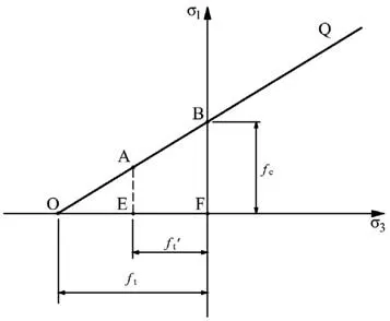
Fig.1.MC failure criterion with tension cut-off in the principal stress space.
To describe the degree of tensile strength reduction,the tensile strength coefficientξ=/ftis introduced.The reduced tensile strengthcan then be expressed as
wherecandφare the cohesion and internal friction angle of soil,respectively.
Michalowski(2017)and Park and Michalowski(2017)examined Paul’s alteration on the Mohr plane,because most stability approaches use the MC criterion in the form of normal stressesσnand shear stresses τ.Fig.2 illustrates the tension cut-off MC criterion inσn-τ space.Fig.2a represents an extreme situation where the tensile strength is reduced to 0 (ξ=0),Fig.2b represents a common case of partial tension cut-off(0 <ξ<1),and Fig.2c considers a‘full’tensile strength with no reduction(ξ=1).f3tandfcin Fig.2 denote the triaxial tensile strength and uniaxial compressive strength of soils,respectively.
Note that every single point(σ1,σ3)in principal stress space can be represented with a stress circle for the limit stress state in Mohr(σn,τ)space.For instance,pointAin Fig.1 corresponds to circleC3in Fig.2b,and pointEmaps onto circleC1.In this way,the cut-off lineAEis represented as a series of stress circles inσn-τ space.These circles all pass through an identical point (σn=-ft′,τ=0) with radius varying from/2 to ((1 -sinφ)/(ccosφ)-sinφ/(1 -sinφ)),since one point on lineAEis determined by the sameσ3=and a special maximum principal stressσ1.The envelope of the circlesC3,sectionSP,substitutes for the previous dashed line segment and continues to a segment of strength envelope in tensile stress regime.It is more convenient to use the smooth strength envelope for limit stress states than the non-smooth yield surface in the principal stress space.
2.2.HB criterion
The generalized HB criterion is written as follows:
whereσciis the uniaxial compressive strength;andmb,Sandαare the HB strength parameters given by
whereGSIis the geology strength index ranging from 5 to 100,miis a material constant that reflects the hardness of rock mass,andDdenotes the disturbance factor of the rock material and ranges from 0 (undisturbed in situ rock masses) to 1 (disturbed rock mass)(Hoek and Brown,2019).
HB criterion gives a sound description of the strength of intact or highly weathered rock mass.However,this criterion was rarely used in limit analysis or limit equilibrium directly,because its yield surface is nonlinear as well as the formulation is in principal stresses form.A common solution is linearizing its nonlinear yield surface inσn-τ space,to be more specifically,taking a MC yield surface inσnand τ space as an approximation to substitute the nonlinear HB surface.
The linearization of the HB failure criterion is mostly realized by two techniques: the generalized tangential method (GTM) (Yang et al.,2004;Sun et al.,2022) and the equivalent MC method(EMCM)(Li et al.,2011;Xu and Yang,2018).As shown in Fig.3,the GTM conducts a tangent of the HB yield surface as the approximate yield surface,while EMCM uses a linear fitting curve to the HB yield surface as the approximation.The corresponding cohesion (cG,cE)and internal friction angle(φG,φE)in MC criterion can be obtained respectively,where the subscript G denotes the GTM and the subscript E denotes the EMCM.However,GTM and EMCM do not considers the presence of tensile strength of rock mass,leading to the modification of GTM and EMCM being necessary.
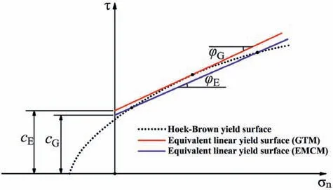
Fig.3.HB criterion and its equivalent linear yield surfaces given by GTM and EMCM.
2.3.Tension cut-off in HB criterion
The proposed method considering tensile strength cut-off in the HB criterion is based on the strategy of EMCM instead of GTM,this is because EMCM has a better performance than GTM at largeGSIand it is needless to search the optimal friction angle(Xu and Yang,2018).The modification of EMCM with tension cut-off is shown in Fig.4,which is named ETMCM.The proposed ETMCM takes an equivalent MC yield surface modified equivalent MC method(EMCM)that is truncated with the tensile strength of rock massσt,to substitute the nonlinear HB yield surface.The intersection of the cut-off line and the linear portion of equivalent MC yield surface is pointK,where the direction of strain rate vector ˙ε rotates fromKStoKP.

Fig.4.Equivalent linear yield surface of HB criterion with tension cut-off (in the principal stress space).
The tensile strength of rock massσtis denoted by the intersection of the HB envelope and theσ3axis,which can be approximately taken as follows:
The determination of the linear portion of the equivalent MC envelope follows the principle of classical EMCM,i.e.balancing the upper and lower areas surrounded by the fitting curve and HB yield surface.The expression of equivalent friction angleφand equivalent cohesioncare given as follows (Hoek et al.,2002):
whereγdenotes the rock mass unit weight,Hdenotes the height of the rock slope,andσ′cmdenotes the compressive strength of the rock mass that can be calculated as follows (Hoek et al.,2002):
In real slopes,the distribution ofis much more complicated,and its accurate solution must be determined by the numerical simulation.But the above equation still provides an effective approach of solving.
Fig.5 shows the equivalent envelope of the proposed ETMCM in the Mohr plane.This is the combination of the linear MC envelope and the nonlinear portion governed by the tensile strength of rock mass.The two portions represent different features of rock mass failure.The linear envelope means that the deformation of materials intends to be a continual shear strain,while in sectionSP,the deformation process can be described as rupture and separation,just like a fracture.The stress vectorT→and velocity vector v→represent the traction and discontinuity of points on the failure surface,respectively.A change ofσ1fromStoPat pointKin Fig.4 corresponds to the rotation of the strain rate vector in Fig.5,in the process of which the dilatancy angleδvaries fromφat pointSto π/2 at pointP.The dilatancy angleδon sectionSPis due to a traction failure behavior,which is different from that in literature (Davis,1968;Mollon and Soubra,2010) where dilatancy angle is associated with a non-associated flow rule.
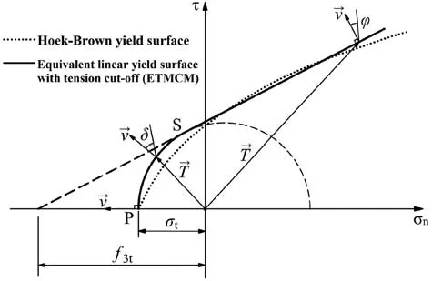
Fig.5.Equivalent linear yield surface given by ETMCM in σn -τ space.
3.Formulation of the problem
3.1.Problem definition and solution method
The 3D rock slope has a simple geometry defined by the heightH,the widthB,and the inclination angleβ.The rock mass is homogeneous intact or isotropic heavily jointed and follows the HB criterion.Due to the absence of large control joints,the failure of slopes can be described by a rotation sliding with the failure surface passing through the slope toe.This failure feature agrees with most observations in practice.The associated flow rule should be satisfied along the failure surface,implying the following relationship:
where vnand vtrepresent the normal and tangential components of the velocity on the sliding surface,respectively.The slope stability is characterized by the safety factorFs,the most common index of the safety margin of a given slope.
3.2.Extended horn-like rotational failure mechanism
Building a suitable failure mechanism is primary in the procedure of kinematic analysis of rock slope.In this work,a one-block failure mechanism with a horn-like contour is adopted.The mechanism proposed by Michalowski and Drescher (2009) is computationally efficient with no need to consider admissible kinematics within the sliding block.Recently,the mechanism was modified by Park and Michalowski(2017)to allow consideration of tension cut-off in the MC criterion.Fig.6 depicts the original and developed mechanism with a cross-section in a vertical symmetrical plane.Every point within the failure mechanism rotates along with the rotating centerO,with the velocity v expressed as
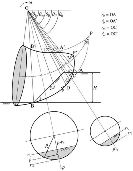
Fig.6.Extended 3D horn-like failure mechanism for HB rock slope.
whereωis the angular velocity rotating around the axis passing through pointO,andρis the rotating radius.The log-spiral contourPBandPB′given by Michalowski and Drescher (2009) can be expressed as
whereθ0is the initial angular coordinate;andr0andr0′denote the radii atθ=θ0,respectively.Since it only applies to the case where the failure of the slope is completely governed by shear strength,the log-spiral contour needs to be modified to consider tensile stress.The modification includes the moving of apexPtoP′and the corresponding deformation of the curves ofP′DandP′D′,as represented by the solid line.The upper part of the mechanism (sectionsP′DandP′D′) is governed by nonlinear segmentSPof the envelope in Fig.5 that represents the tension cut-off,while the remaining partsB′D′andBDare still governed by the linear MC portion of the envelope.
An infinitival element along the surface in section P′D is shown in Fig.7,with the following differential equation:
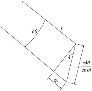
Fig.7.Infinitesimal element of failure surface for rock slopes with tensile strength cutoff.
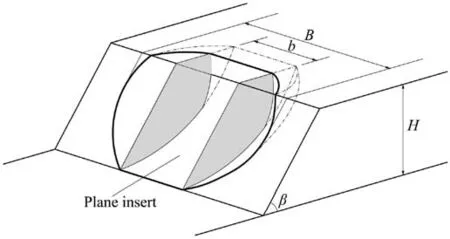
Fig.8.3D horn-like failure mechanism with a block inserted in the symmetrical plane.
whereθis the angle between the sliding surface and the velocity vector.Then the radiusrcorresponding to the curve CD can be obtained:
where(θm,rm)is the angular coordinate and radius of pointC,θmis an unspecified angle that needs to be clarified by searching,andrmcan be expressed as
To give a specific geometry of the sliding surface,the functionδ(θ)needs to be determined.Previous research indicated that a linear variation ofδalong with the rotation angleδgives the best estimation of the slope stability (Michalowski,2017).Thus,the function ofδ(θ)is expressed as follows:
whereδmis the maximum dilatancy angle at pointC,andθtcis the angular coordinate of pointD.
In addition,as the dilatancy angle varies,the corresponding cohesion can be given as
wherertis the radius of the non-linear portion of the strength envelope in ETMCM,and can be expressed as
PointDconnects the upper and lower parts of the mechanism.Thus,the radius at pointDcan be determined as follows:
The above equation can be simplified to obtainδm,as follows:
Similar to the curveCD,the curveC′D′can be expressed as
where(θm,rm′) is the coordinates of pointC′.
Considering pointD′is the common point of sectionsC′D′andB′D′,the equation of its radius is obtained as follows:
Then,we have
Thus,the upper and lower limit curves in the symmetry plane can be described as
The radial cross-section of this mechanism is shaped as a circle,of which the radiusRand the enter racerccan be determined as follows:
The failure characteristics change from 3D to 2D gradually with the increase of the slope width.To reflect this tendency a block with widthbis inserted into the symmetry plane of the horn-like mechanism,as shown in Fig.8.This inserted block comes from the stretching of a 2D failure surface taking into account the tension cut-off (Michalowski,2017).The widthbcan be written as
3.3.Work rate balance equation
The upper bound solution of slope stability can be sought from the energy balance equation:
whereW3DandWbare the external work rates of horn mechanism and inserted block,respectively;andD3DandDbare the corresponding parts of energy dissipation.
In the present mechanism,the external work rate is due to gravity,while the internal dissipation occurs only along the sliding surface.The value of the external work rate can be calculated by volume integral as follows:
whereVis the volume of the intersection of the mechanism and slope body,γis the weight of the material,and v cosθdenotes the vertical component of the velocity vector.Infinitesimal element dVhere can be expressed as
More specifically,the external work rate can be expressed as
It is easy to give the upper and lower bounds of the integralr1andr2according to the geometric relationship:
Energy dissipation can be calculated by area integral as follows(Park and Michalowski,2017):
whereSis the area of the failure surface.When the element belongs to the log-spirals partDBgoverned by the linear envelope,the internal dissipation equation reduces to:
where infinitesimal area element dScan be expressed as
Consequently,energy dissipation of this mechanism can be specifically expressed as
The calculation ofWbandDbof the inserted block can be found in Michalowski (2017).
3.4.Safety factor and solution
The strength reduction technique is taken to calculate the safety factor of the slope,whereFsis the reduction factor ofcand tanφthat renders the limit state of slope failure:
wherecandφare the MC strength parameters of geomaterials,andcdandφdare those to provide a limit equilibrium state.
In addition,it has been verified that with a givenGSI,miandβ,the safety factorFsof rock slopes is only related toSR=σci/(γH)(Xu and Yang,2018).Similarly,the expression ofFscan be transformed to be the following optimal problem:
whereθ0,θtc,θm,θhand/r0are optimized under the following restrictive condition:
A procedure based on the dichotomy strategy is introduced to numerically determineFs.The steps are detailed as follows:
(1) Input the basic parameters of slopeSR=σci/(γH),GSI,mi,Bandβ,and then the upper and lower bounds of the safety factorsFs1andFs2can be sought.The parametersc,φandξof the modified equivalent MC envelope method can be determined from the given HB parameters.
(2) Assign safety factorFs=(Fs1+Fs2)/2 and reduce the strength parameter tanφandcby the present value ofFs.
(3) Search for a set of variablesθ0,θtc,θm,θhandr0′/r0that can render an upper bound mechanism with the reduced strength.For simplicity,the exhaustive strategy is used with the interval of 0.05 rad forθ0,θtc,θmandθh,and 0.02 forr0′/r0.
(4) SetFs2=Fsif an upper bounder mechanism can be determined,otherwise makeFs1=Fs.
(5) Repeat Step 2 to Step 4 untilFs1-Fs2is less than a presumed valueδFs=0.005.The value of(Fs1+Fs2)/2 is the final solution ofFs.
4.Comparison and validation
The proposed ETMCM is validated by theoretical studies and numerical simulations.Firstly,the present solutions are compared with the previous results without consideration of the tensile strength,as there were no published solutions of 3D HB slope with tension cut-off.Xu and Yang (2018) used the classical EMCM to analyze the stability of the 3D HB slope.A comparison is conducted between their findings and the present solutions from ETMCM,whereξis set to 1 to exclude the effect of tension cut-off.As shown in Table 1,the comparison indicates that these two solutions are close with the maximum error of 5%.The good agreement indicates the validity of ETMCM and the calculation procedure.
Besides,the present solutions are verified by comparison with the numerical simulation using FLAC3D.The numerical model has the parameters as follows:H=50 m,B/H=3,GSI=50,mi=25,σci=10 MPa,Poisson’s ratioυ=0.3,Young’s modulusE=10 GPa,andβranging from 70°to 90°.The model boundary conditions are as follows:the displacement fixed at the front and back surfaces iny-direction,the displacement is fixed at the side surfaces inx-direction,and displacement is fixed at the base surface inx-,yandz-direction.It is noted that the MC criterion is adopted in FLAC3D with the MC strength parametersc=137.4 kPa,φ=56.5°andξ=0.11,which are derived from the HB parameters using the proposed ETMCM.The reason to do this is that FLAC3D handles the nonlinearity of the HB criterion in a quite different way than ETMCM.Using the HB criterion in FLAC3D will lead to less authenticity in the validation.The geometry of the FLAC3D model is plotted in Fig.9.The numerical results of the slope withβ=80°are given in Fig.10.
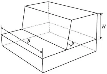
Fig.9.Geometry of 3D HB rock slopes in the numerical model.
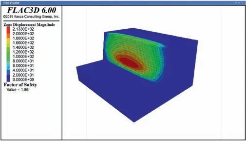
Fig.10.Numerical simulation results of a slope example given by FLAC3D with tension cut-off(β=80°).
Table 2 summarizes these results of FLAC3D and the proposed ETMCM with and without tensile strength cut-off.As listed in the last column,the impacts of tension cut-off on safety factors given by the two methods are similar.This implies that the EMCM properly reflects the effect of the tensile strength in the 3D stability of the HB slope.It is also observed that this effect grows with increasing slope inclination,which will be discussed in detail in the next section.
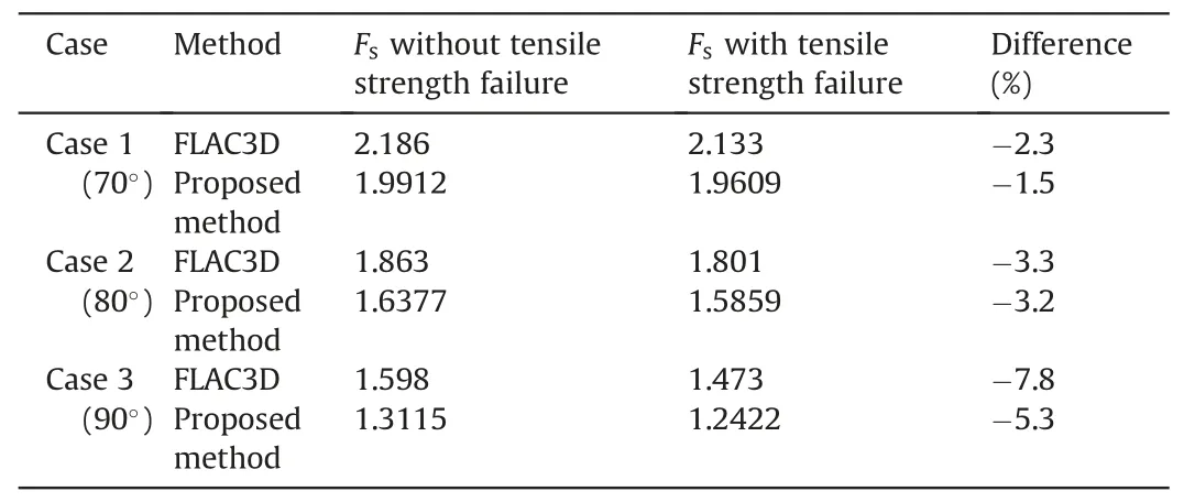
Table 2Comparisons of safety factors given by the proposed limit analysis-based method and FLAC3D.
5.Results and discussion
The tensile strength influence on 3D rock slope stability is rarely considered in existing studies.It is interesting to find out the impacts of tensile strength on safety factors and its variation with other factors.A set of safety factor solutions with/without tension cut-off (EMCM and ETMCM) is sought from the proposed method and given in the graphs.These graphical results offer great convenience to geotechnical engineers in the design process of HB rock slopes.
5.1.Influence of slope geometric parameters
The results with the variation of slope inclination from 50°to 90°are given in Fig.11,where the basic parameters areGSI=30,mi=10,andSR=10 for case 1 in Fig.11a;andGSI=70,mi=25,andSR=1 for case 2 in Fig.11b.It is found that the curves with and without a tension cut-off are overlapped at small slope inclination,and tend to diverge with the increase ofβ.It emerges that the steep shape can significantly increase the effect of tension cutoff,particularly for inclinations larger than 60°.This observation is described more in detail in Fig.12a,where the relative decrement caused by the tension cut-off for case 1 is plotted along with slope inclination.It can be found that tensile strength cut-off has an obvious influence asβincreases.This indicates that more attention should be paid to the influence of rock tensile strength in the design of steep rock slopes.In addition,Fig.11 also illustrates that the increase ofB/Hleads to an increase in the effect of rock tensile strength.As depicted in Fig.12b,the relative reduction of safety factors grows sharply whenB/H<2,and its increasing velocity becomes smoother whenB/His larger than 5.This means that the effect of tensile strength cut-off should not be neglected,especially for rock slopes with relatively large widths.
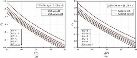
Fig.11.Safety factors versus β considering the variation of B/H: (a) GSI=30,mi=10,SR=10;and (b) GSI=70,mi=25,SR=1.
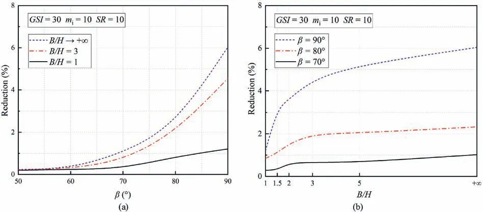
Fig.12.Relative reduction of safety factor with tension cut-off: (a) Reduction versus β with different B/H values,and (b) Reduction versus B/H with different β values.
5.2.Influence of HB parameters
In the present method,strength parameters in the HB criterion not only decide the linear portion of the equivalent MC envelope but also impacts the nonlinear portion governed by the tensile strength.The effects of geology strength indexGSI,HB constantmi,and dimensionless parameterSRon safety factors are investigated,to give a comprehensive description that how HB parameters influence the solution with a tension cut-off.Figs.13-15 give the solutions with and without considering the tension cut-off with the variations ofGSI,miandSR,respectively,for two slope inclinations of 75°and 90°.
Figs.13 and 14 indicate that the effects of considering tensile strength is only weakly related to the changes ofGSIandSR.For example,in Fig.13b withGSI=50,mi=15,β=90°andB/H=5,reduction of safety factor only changes 0.01 by arising theSRfrom 1 to 5.It is manifested from Fig.15 that the influence of tensile strength cut-off on slope stability becomes more significant with the increase ofmi.Asmichanges from 5 to 35 in Fig.15b,such a difference induced by tensile cut-off increases 3 or 4 times.Hence,it can be speculated that the influence of tensile strength is more prominent for hard rock masses.Besides,Figs.13-15 indicate that both slope inclination and slope width have a positive effect on the effects of tension cut-off.This is a good agreement with the discussions above.
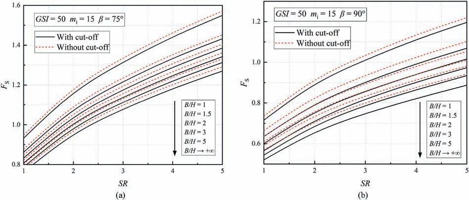
Fig.13.Safety factors versus SR considering the variation of B/H: (a) GSI=50,mi=15,β=75°;and (b) GSI=50,mi=15,β=90°.
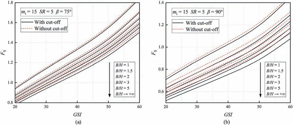
Fig.14.Safety factors versus GSI considering the variation of B/H: (a) mi=15,SR=5,β=75°;and (b) mi=15,SR=5,β=90°.
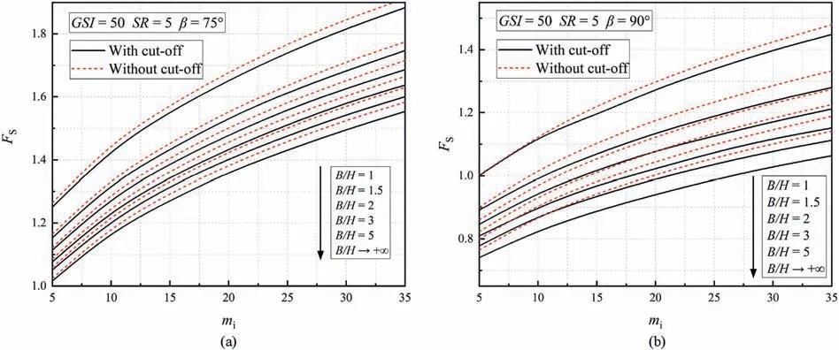
Fig.15.Safety factors versus mi considering the variation of B/H (a) GSI=50,SR=5,β=75°;and (b) GSI=50,SR=5,β=90°.
5.3.Failure surfaces change due to tension cut-off
In practice,our concern about the effect of tension cut-off is not only on safety factors of slopes but also with respect to the failure surfaces.Fig.16 shows the profiles of slope failure surface obtained from EMCM and ETMCM,whereβ=75°or 90°,andB/H=2 or approaches +∞.The dashed line represents those obtained by the classical method (EMCM),while the solid lineDCBindicates those considering tension cut-off (ETMCM).SectionBCis dominated by the tension failure,and sectionCDis governed by the linear portion of the strength envelope.The extension of the log-spiral surface is denoted by the grey line.It is found that the change of failure block is affected by slope inclination.The area of the failure block subjected to tensile stress is enlarged withβincreasing from 75°to 90°.This can explain the observation in Figs.11-15 that tension cut-off causes a more significant variation of safety factors at a larger slope inclination.From Fig.16,we also find that the variation ofB/Hhas a considerable effect on the tensile portion of the failure surface.With the increase ofB/H,the surface portion governed by the tensile strength has a trend to decrease.However,B/Hhas less contribution to the enlargement of the tensile failure regime than slope inclination.It is believed that the proposed method provides a more accurate sliding surface description than the classical method,because its equivalent strength envelope realistically covers the compression and tension regions of the rock mass.

Fig.16.Failure surfaces of 3D HB rock slopes with/without tension cut-off:(a)β=90°,B/H→+∞;(b)β=75°,B/H→+∞;(c)β=90°,B/H=2;and(d)β=75°,B/H=2.
5.4.Influence of seepage on slopes
It is practically meaningful to investigate the effect of tension cut-off on slopes under seepage since the presence of seepage is a common trigger of the failure of rock slopes.However,it is difficult to determine the distribution of pore water pressure associated with seepage,as it varies with the hydraulic boundary for a specific slope.For simplicity,a presumed distribution of pore water pressureusuggested by Bishop and Morgenstern (1960) is used here.It assumes that the pore water pressure within a slope is directly related to its vertical distance to the ground surface:
wherehis a vertical distance from a point where the pressure is to be determined to the ground surface,γis an average bulk unit weight alongh,andruis a coefficient loosely related to the presumed phreatic surface.
The external work rates by pore water pressure can be expressed as
The solutions considering seepage are plotted in Fig.17 for two cases.In case 1,GSI=70,mi=25,SR=20,andru=0.3,while in case 2,GSI=40,mi=15,SR=10,andru=0.15.It can be found that tension cut-off provides a conservative safety factor as well in seepage scenarios.For instance,the safety factor of slopes with seepage is 1.96 (β=75°) without considering tension cut-off and drops down to 1.46 when tensile strength is considered.More notably,the presence of seepage enlarges the effects of tensile strength on factor safety.In Fig.18,whenβ=70°andB/H=5,the relative reduction of safety factor increases from 5%to 20%withrufrom 0.2 to 0.3.The results show that the tensile strength cut-off should be carefully considered when seepage is encountered in practice.
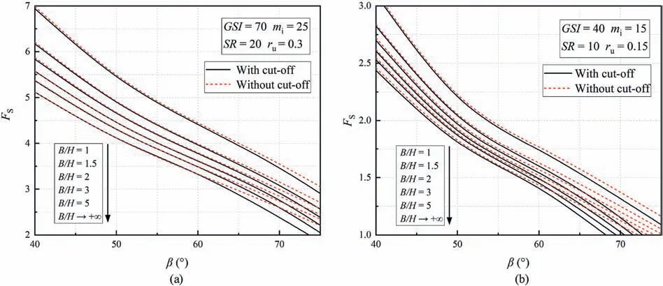
Fig.17.Safety factors under seepage versus β considering the variation of B/H: (a) GSI=70,mi=25,SR=20,ru=0.3;and (b) GSI=40,mi=15,SR=10,ru=0.15.

Fig.18.Relative reduction of safety factor under seepage:(a)Reduction versus ru with different β values,(b)Reduction versus B/H with different β values,and(c)Reduction versus β with different B/H values.
6.Conclusions
Typical stability analysis of intact and/or severely jointed rock slope subjected to the HB criterion rarely considers the tensile strength of rock mass.The motivation of the present work is to propose a theoretical approach that can efficiently produce the safety factor solution of 3D HB slope with limited rock tension strength.This is particularly favorable for the primary stability evaluation or reliability analysis of rock slopes.Using the proposed approach,the influence of tensile strength on the slope stability outcomes are also investigated.
ETMCM is proposed to carry out the HB linearity.ETMCM is established by introducing a tension cut-off strategy to the classical equivalent MC method.In the Mohr plane,the proposed ETMCM yield surface is combined by the linear portion governed by the classical MC criterion and the nonlinear portion dominated by the tensile strength of rock mass.The kinematic limit analysis takes a modified horn-like mechanism that satisfies the admissible kinematic associated with the nonlinearity of the ETMCM yield surface.The outcomes given by the present approach indicate that the safety factor considering tension cut-off is less than those with the conventional approach,and the corresponding failure surface of the slope is affected by tensile strength as well.
Solutions given by ETMCM show that the tension cut-off consideration is negligible for the gentle slope,whereas its effect is increased significantly when slope inclination is larger than 60°.The difference between solutions with/without tension cut-off can exceed 10% for vertical slope.The slope width also impacts the effect of tensile strength.Increasing the ratio of width to height enlarges the safety factor drop caused by tension cut-off.Calculations also indicate that the failure governed by the tensile strength occurs near the slope crest,which leads to a steeper slip surface in the head region.The presence of seepage greatly enriches the effect of tension cut-off.Results reveal that the drop in safety factor due to tensile strength atru=0.3 can be four times larger than that under weak seepage conditions (ru=0.1).
In general,the effect of tensile strength should be examined in the 3D HB rock slope stability analysis,particularly for the cases with large slope inclination,slope width and more severe seepage conditions.The variation of failure surface due to tension cut-off also needs to be paid attention to when considering reinforcement associated with failure surface depth,such as anchor and anti-sliding pile.The proposed method offers a useful tool to investigate the effect of rock tensile strength under common conditions;however,the impact of tension cut-off under severe scenarios (e.g.earthquake and seepage) deserves a systematic study.These can be achieved with the given failure mechanism by adding the corresponding external work rate.
Declaration of competing interest
The authors declare that they have no known competing financial interests or personal relationships that could have appeared to influence the work reported in this paper.
Acknowledgments
This work is supported by the National Natural Science Foundation of China (Grant Nos.U22A20594 and 52108312).
 Journal of Rock Mechanics and Geotechnical Engineering2023年12期
- Journal of Rock Mechanics and Geotechnical Engineering的其它文章
- The formation of orthogonal joint systems and cuboidal blocks: New insights gained from flat-lying limestone beds in the region of Havre-Saint-Pierre (Quebec,Canada)
- Numerical analysis of the effects of vesicle distribution characteristics on the engineering properties of volcanic rocks
- A hybrid attention deep learning network for refined segmentation of cracks from shield tunnel lining images
- Mutual impact of true triaxial stress,borehole orientation and bedding inclination on laboratory hydraulic fracturing of Lushan shale
- Unloading-induced permeability recovery in rock fractures
- An open-end high-power microwave-induced fracturing system for hard rock
