Mutual impact of true triaxial stress,borehole orientation and bedding inclination on laboratory hydraulic fracturing of Lushan shale
Yongf Zhng,Anf Long,Yu Zho,*,Arno Zng,Cholin Wng
a College of Civil Engineering,Guizhou University,Guiyang,550025,China
b Helmholtz Centre Potsdam,GFZ German Research Centre for Geosciences,Potsdam,14473,Germany
Keywords:True triaxial hydraulic fracturing experiment In situ stress state Bedding planes Natural fractures Wellbore orientation Shale reservoirs
ABSTRACT Unconventional resources like shale gas has been the focus of intense research and development for two decades.Apart from intrinsic geologic factors that control the gas shale productivity(e.g.organic matter content,bedding planes,natural fractures,porosity and stress regime among others),external factors like wellbore orientation and stimulation design play a role.In this study,we present a series of true triaxial hydraulic fracturing experiments conducted on Lushan shale to investigate the interplay of internal factors (bedding,natural fractures and in situ stress) and external factors (wellbore orientation) on the growth process of fracture networks in cubic specimens of 200 mm in length.We observe relatively low breakdown pressure and fracture propagation pressure as the wellbore orientation and/or the maximum in situ stress is subparallel to the shale bedding plane.The wellbore orientation has a more prominent effect on the breakdown pressure,but its effect is tapered with increasing angle of bedding inclination.The shale breakdown is followed by an abrupt response in sample displacement,which reflects the stimulated fracture volume.Based on fluid tracer analysis,the morphology of hydraulic fractures(HF) is divided into four categories.Among the categories,activation of bedding planes(bedding failure,BF)and natural fractures (NF) significantly increase bifurcation and fractured areas.Under the same stress regime,a horizontal wellbore is more favorable to enhance the complexity of hydraulic fracture networks.This is attributed to the relatively large surface area in contact with the bedding plane for the horizontal borehole compared to the case with a vertical wellbore.These findings provide important references for hydraulic fracturing design in shale reservoirs.
1.Introduction
As a typical unconventional resource,tight shale formations are characterized by ultra-low porosity (4%-6%) and permeability(<10-21m2) (Ahmed and Meehan,2016),which impedes the efficient extraction of hydrocarbons using conventional extraction methods.Hydraulic fracturing has been widely implemented in the stimulation of shale gas reservoirs (Hunter,2016;Belyadi et al.,2019;Li et al.,2022,2023).During the hydrofracturing process,high-pressure fluid is injected into shale reservoirs,and massive artificial fractures are created,which greatly enhances shale permeability and gas migration (Bennour et al.,2015;Li et al.,2016a).According to Guo et al.(2021),the key to commercial exploitation of shale gas reservoirs is to create complex fracture networks with a large stimulated reservoir volume(SRV).However,due to the geological complexity and bedding anisotropy,unfavorable hydraulic fracture initiation and propagation may occur,resulting in short and compact fractures.To create long persistence with multiple branches in anisotropic shale reservoirs,it is crucial to elucidate the formation mechanism of complex fracture networks.It is well established that shale anisotropy,in situ stress,and borehole orientation are key factors that control the nucleation and propagation of hydraulic fractures.Current research efforts usually focus on the individual investigation of these factors,while their mutual impact remains unclear.We see further systematic studies necessary to reveal the interrelation of these factors controlling hydraulic fracture growth.
At first,shales are intrinsically anisotropic and heterogeneous sedimentary rocks.The discontinuities induced by bedding planes and natural fractures significantly affect the shale’s mechanical properties and fracture characteristics (He et al.,2020;Zuo et al.,2020;Bi et al.,2020,2023).Heng et al.(2015,2020) studied the effect of bedding inclination on the shear strength and failure mechanism of shales.They concluded that the shear strength,cohesion and internal friction angle reached the minimum and maximum values when the bedding inclination was 0°and 60°,respectively.Jin et al.(2018) measured the tensile strength of Marcellus shale at different bedding inclinations,indicating that the direct tensile strength increased while the Brazilian tensile strength decreased with increasing bedding angle.Yang et al.(2019,2020a) analyzed the deformation and failure characteristics of anisotropic shale samples and reported that the bedding inclination greatly affected the elastic modulus,tensile strength and failure modes.Herrmann et al.(2018,2020) argued that the mechanical properties and creep behaviors of shales were strongly influenced by sample composition.The structural characteristics of shale gas reservoirs determine whether economic and effective hydraulic fracture networks can be easily designed.Therefore,the anisotropy of shale has a significant impact on the initiation and propagation of hydraulic fractures.
Several studies (Li et al.,2018a,b;Zhang et al.,2021) explored the effects of bedding planes on dynamic hydraulic fracture propagation.The results show that arrest,dilation,offset,branching and crossing may occur when a hydraulic fracture approaches a bedding plane(Thiercelin et al.,1987;Zhao et al.,2021,2022a,b,c).Zou et al.(2017) explored the effects of bedding planes’ permeability and density,which indicated that bedding planes with high permeability and small spacing were prone to impede the growth of hydraulic fractures.In terms of bedding inclination,Lin et al.(2017),Chong et al.(2019) and Zhao et al.(2021) reached a consensus that the breakdown pressure showed an initial increase and then decrease with the increase of bedding inclinations.Heng et al.(2020) confirmed the relatively low strength of bedding planes in comparison to the rock matrix and reported that a favorable complex fracture geometry was obtained if the main hydraulic fracture evolved normal to the bedding planes.Analyzing hydraulic fracture propagation in shale with horizontal bedding,Tan et al.(2020)classified the fracture morphology into four types:simple horizontal hydraulic fracture,transverse hydraulic fracture,step-shaped hydraulic fracture with fissure opening and multilateral fishbone-like hydraulic fracture networks.In shale cores with different bedding inclinations,Wang et al.(2021) observed three failure patterns,which are splitting,split-bending and splitting along the bedding plane,respectively.In general,previous studies mostly focused on the propagation of hydraulic fractures in horizontal bedding conditions,but little work has been done on the variation of bedding inclination under a true triaxial in situ stress state which is the actual case in anisotropic shale formations(Zhao et al.,2021,2022a).
Besides bedding anisotropy,in situ stress is a controlling factor in the formation of hydraulic fracture networks in shale reservoirs(Zou et al.,2016).Current research focuses on the effect of differences in situ stress magnitudes on the hydraulic fracture networks(Guo et al.,2014;Zhang et al.,2019a,b).In the case of high differential stress,hydraulic fractures are likely to propagate aligned with the maximum principal stress,which leads to limited height growth and simple fracture morphology.Out of the three Andersonian stress regimes,normal faulting(σv>σH>σh)and strike-slip(σH>σv>σh) are common in shale plays (Hossain et al.,2000;Amini and Eberhardt,2019).Few studies have focused on the formation mechanism of fracture networks under anisotropic stress states.When simulating deviatoric stresses in the laboratory,either the normal faulting stress state(Li et al.,2018a,b;Jiang et al.,2019;Yang et al.,2020b) or the strike-slip stress state (Tan et al.,2017;Zhang et al.,2019b) has been investigated.Zhou et al.(2008)compared the fracture propagation behavior under the normal faulting and strike-slip stress regimes.They pointed out that in the normal faulting regime,the hydraulic fractures propagated vertically without reorientation,while in the strike-slip state,the hydraulic fractures were tortuous and non-planar.Guo et al.(2014)performed shale hydrofracturing experiments and reported that more horizontal bedding planes were activated in the strike-slip stress state.However,both Zhou et al.(2008) and Guo et al.(2014) were unable to maintain the same stress magnitudes in both regimes during laboratory testing.In this study,we overcome this problem,and further evaluate the impact of true triaxial constant stresses with respect to bedding plane orientation.
Third,the wellbore orientation (external factor) plays a pivotal role in forming fracture networks(Lin et al.,2017;Guo et al.,2021).Current hydraulic fracturing experiments were performed either using horizontal boreholes (Guo et al.,2014;Jiang et al.,2019;Zhang et al.,2019b) or vertical boreholes (Heng et al.,2014).Recently,Guo et al.(2021) compared the fracturing characteristics of horizontal and vertical boreholes and found that the breakdown pressure of horizontal borehole hydraulic fracturing was lower than that of the vertical borehole.They concluded that the horizontal borehole produced horizontal transverse fractures,while the vertical borehole mainly induced vertical transverse fractures.However,Guo et al.(2021)’s experiments lacked a true triaxial stress state(i.e.σ2=σ3),and the sample size changed from the case of horizontal to the case of a vertical borehole.
A systematic study on the combined effect of in situ stress,bedding inclination and wellbore orientation on the formation of shale fracture networks is still missing.Closing this knowledge gap is the major motivation and aim of this study.Two stress states(normal faulting and strike-slip) with constant stress magnitudes,two cases of bedding plane inclinations (0°and 45°),and two wellbore orientations (horizontal and vertical) and their combinations are considered.Six true triaxial tests on cubes of Lushan shale are performed,and resulting hydraulic fracture morphology is quantified using a fluorescent tracer under ultra-violet light.The number and inclination of fractures,as well as the stimulated rock volume,are characterized.Results are discussed in the framework of shale gas field applications.
2.Experimental materials and methods
2.1.Test apparatus and sample preparation
To simulate the ambient in situ stress conditions in shale formations,a true triaxial hydraulic fracturing system is used,as shown in Fig.1.The experimental setup consists of a true triaxial loading frame (Fig.1a),pressure control system (Fig.1b),displacement monitoring system(Fig.1c)and fluid injection system(Fig.1d).The loading frame consists of a pressure vessel with a cubic skeleton and six pistons that apply compressive load in three orthogonal directions to the cubic sample(Fig.1a).The true triaxial stress state of rock samples is maintained by the pressure control system (Fig.1b) with maximum loading capacity and minimum measurement accuracy of 50 MPa and ±0.1% of full scale,respectively.The deformation of rock samples is measured in real-time by contact-type displacement sensors integrated in the loading plates(Fig.1c),blue solid rectangles).The measurement accuracy of the displacement sensors ranges from 0.001 mm to 30 mm.The fluid injection is controlled by a TC-100 D dual syringe pump (Fig.1d)with a maximum pumping pressure of 70 MPa.This pump can be operated in either constant pressure or constant flow rate control mode.In this study,a 20 mL/min constant injection rate is maintained in all hydraulic fracturing tests.
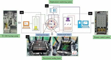
Fig.1.True triaxial hydraulic fracturing test system consisting of (a) steel loading frame,(b) pressure control system,(c) displacement monitoring system,and (d) fluid injection system.
The shale blocks used for hydraulic fracturing experiments are sourced from the Upper Sinian shale formation outcrops with the weathered surface removed in Jiurui Basin,Lushan,China(Fig.2a),hereafter called Lushan shale.After cutting and polishing,the shale blocks are processed into cubic samples with a side length of 200 mm and different bedding orientations(0°,45°and 90°)with respect to the borehole orientation (Fig.2a).As shown in Fig.2b,clear bedding planes are identified on the shale surface,which cause anisotropic behavior(Choi et al.,2015;Cao et al.,2020;Wang et al.,2022).Microscopic inspection reveals that there are natural fractures (20-500 μm in length) and isolated pores in the shale samples.The permeability and porosity measured at room temperature are (1.04 ± 0.11) × 10-3mD and 4.24% ± 0.24%,respectively.The mineral composition of Lushan shale analyzed by X-ray diffraction includes illite (40.7%),quartz (25.4%),clinochlore(15.1%),albite low (8.7%),muscovite (6.6%),calcite (2.5%),and kaolinite (1%).
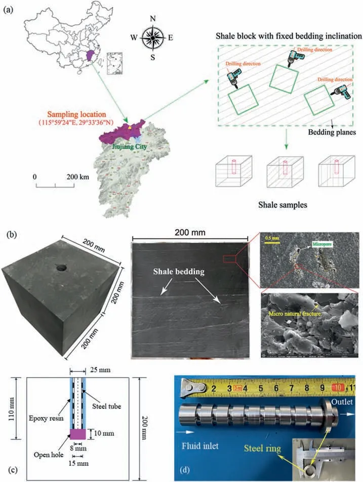
Fig.2.(a)Sample location and processing of Lushan shale schematically,(b)Cubic shale sample with microscopic details of the bedding planes,(c)Geometry and inner structure of the fluid-injection borehole and the packer system,and (d) Steel injection tube used for hydraulic fracturing tests.
As shown in Fig.2c,an injection hole (24 mm in diameter and 110 mm in length)is drilled from the top surface of the specimen to mimic the wellbore.A high-strength 42CrMo steel pipe (Fig.2d)with an outer diameter of 15 mm and an inner diameter of 8 mm is fixed to the eyehole,leaving a 10 mm open hole section for fluid injection.An epoxy adhesive is used to seal the casing and the prefabricated wellbore.To prevent the adhesive from blocking the fluid outlet and flowing into the open hole section,a steel ring is welded to the bottom of the steel tube(Fig.2d).Before the test,the sample is placed into an oven for 48 h with a constant temperature of 30°C to achieve optimum sealing.
2.2.Experimental procedure
2.2.1.Test configuration and systematics
We investigate three cases of bedding inclination with respect to well orientation(Fig.3).Cases 1 and 2 are the schematic diagrams of wells that are vertical and horizontal to shale bedding,respectively,and Case 3 indicates an inclined well with respect to the shale bedding planes.We follow the approach of Beugelsdijk et al.(2000) to avoid the pre-fracturing of Lushan shale when applying initial stress conditions.This allows us to simulate normal and strike-slip stress regimes with a constant deviator stress(σmax-σmed=σmed-σmin)of 3 MPa and a minimum in situ stress magnitude of 6 MPa.
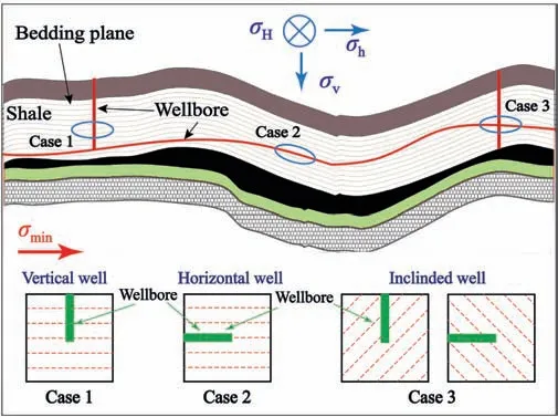
Fig.3.Schematic diagram of the relationship between the borehole and the shale bedding plane orientation.Case 1:a vertical well perpendicular to bedding plane,Case 2:a horizontal well parallel to bedding plane,and Case 3:an inclined well with respect to bedding planes.
In total,six samples are prepared for hydraulic fracturing tests with different bedding inclinations,in situ stress states and borehole orientations,as summarized in Table 1.The impact of bedding planes is considered in samples#1 and#2(Case 1,90°with respect to the borehole),samples#3 and#4(Case 3,45°with respect to the borehole),and samples #5 and #6 (Case 2,0°with respect to borehole).The effect of stress field is investigated by comparing results from samples #1,#3 and #5 under the normal faulting stress regime and results from samples #2,#4 and #6 under the strike-slip stress regime.The influence of borehole orientation is covered by testing samples #1-#3 (vertical well fracturing perpendicular to the direction ofσmin) and samples #4-#6 (horizontal well fracturing parallel to the direction ofσmin).It is assumed that the maximum stressσmaxis a principal stress.Comparing results from different pairs of tests allows to investigate the mutual impact of different factors controlling hydraulic fracture growth.
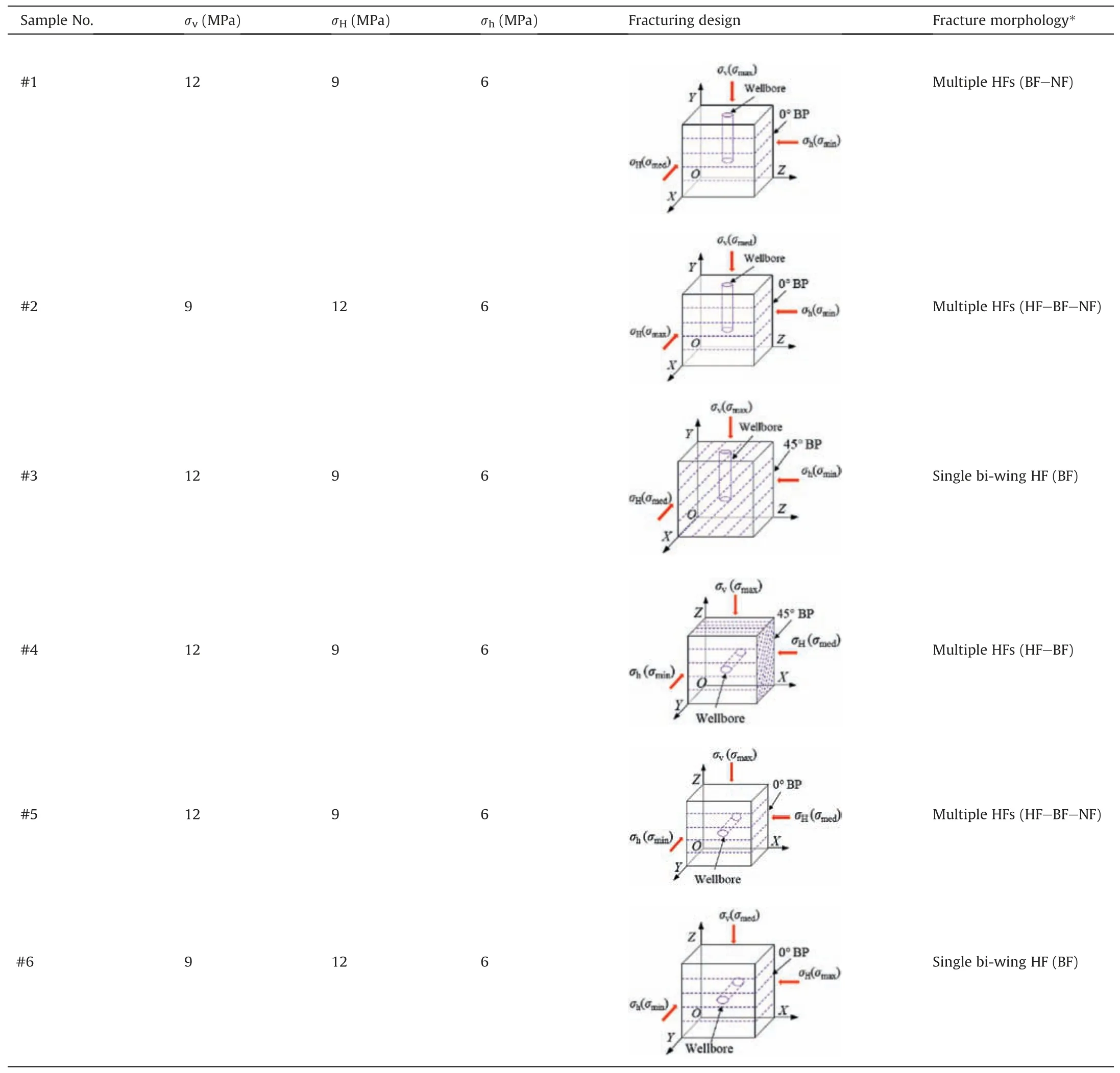
Table 1Hydraulic fracturing test conditions and observed fracture morphology.
The hydraulic test procedure is as follows.First,the sample is emplaced into the true triaxial vessel(Fig.1a).Second,the three in situ stress magnitudes(σv,σHandσh)are simultaneously applied to the sample surfaces at a constant loading rate of 0.5 MPa/min.Once the in situ stress in one direction reaches the preset value,this stress will remain constant,while the stresses in other directions will continue to increase at the same rate.When all stress magnitudes reach predetermined values (Table 1),a 30-min holding period is maintained to allow steady stress state conditions.Third,fluid injection starts at a constant flow rate of 20 mL/min until the sample is hydraulically fractured.During the test,the in situ stresses are recorded in real time.Rock deformation caused by fluid injection is recorded via displacement sensors.The fluid pressure system monitors the evolution of fluid pressure versus time.As soon as fracturing fluid leaks out of the triaxial chamber,the hydraulic fracturing pump is stopped manually.In the fourth step,triaxial stresses are unloaded,and the fractured sample is removed from the chamber for further analysis.
2.2.2.Fracture inspection viafluorescent tracer
To observe the fracture propagation trajectory,a water-based fluorescent reagent (LUYOR-6200) easily dissolving in water is added to the fracturing fluid before the experiment.The fluorescent reagent is strictly controlled in a small amount (~1 mL),not to change the viscosity value of the fracturing fluid.The mixed fluid emits visible fluorescence after exposure to ultra-violet light.Once a hydraulic fracture is initiated and propagated,the mixed fluid leaks out of the shale.The hydraulic fracture morphology is quantified via a digital camera.All digital photos obtained are analyzed to obtain the total number of fractures and their orientations.
3.Experimental results and analysis
3.1.Evolution of pressure and displacement in shale cubes
Fig.4 shows the fluid pressure and displacement curves versus time during the hydraulic fracturing process for all six cases indicated in Table 1.Note thatX,YandZin this figure refer to the rock displacement components in directions ofX-,Y-andZ-axis.Positive deformation represents lateral expansion of the sample (crack opening),and negative deformation indicates contraction of the sample (crack closure).
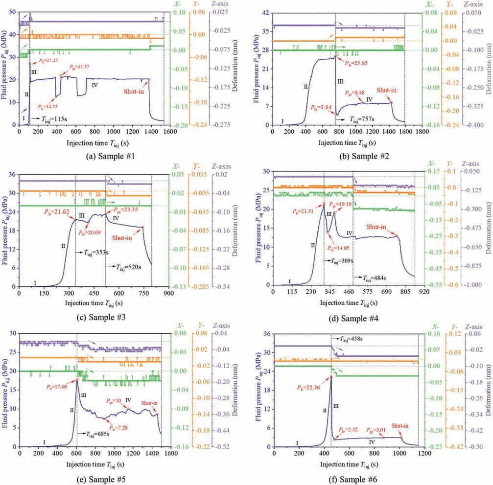
Fig.4.Fluid pressure and sample deformation versus time of six hydraulic fracturing experiments on Lushan shale with test conditions indicated in Table 1.
3.1.1.Fluid pressure response
As seen in Fig.4,the fluid pressure curves follow four typical stages,which are the slow pressurization stage (Fig.4,I),rapid pressurization stage(Fig.4,II),pressure releasing stage(Fig.4,III),and pressure stabilization stage (Fig.4,IV),respectively.The fluid pressure increases slowly after the syringe pump is started(stage I).With the continuous injection of fracturing fluid,the fluid pressure starts to increase and finally reaches the peak pressure (stage II)Then,the fluid pressure drops (stage III) to the lowest value (Ple).This pressure drop is attributed to fluid loss in the wellbore associated with the opening of fractures and the increasing permeability,which release the accumulated fluid pressure.Afterwards,the fluid pressure enters stage IV and stabilizes gradually.The shutin shown in Fig.4 indicates the manual termination point of the syringe pump,which is manifested in zero injection rate and subsequent decline in fluid pressure.
Comparing the fluid pressure curves of all samples,notable differences can be found in stages II and IV.As the wellbore is perpendicular to the bedding plane and aligned with the maximum in situ stress (i.e.sample #1),two significant pressure drops are observed in stage IV (Fig.4a,Tinj=382 s and 612 s).This may be related to the re-initiation and subsequent arrest behavior of the hydraulic fractures,which alternatively reduce and increase the fluid pressure(Zhao et al.,2022a).By contrast,the increase rate of the fluid pressure of samples #2 and #3 both decrease before the peak pressure in stage II,which might be attributed to local leak-off associated with different fracture growth rates and behaviors (e.g.fracture initiation,opening and slippage) caused by the rock/bedding heterogeneity during fluid pressurization(Hou et al.,2016;Hu et al.,2020).In sample#4 with a 45°bedding plane with respect to the borehole and the maximum in situ stress(Table 1),another pressure peak appears after the breakdown (Fig.4d,Tinj=371 s),which may correspond to fracture re-initiation in stage IV.In the case of the bedding plane subparallel to the horizontal borehole,the fluid pressure curves of samples #5 and #6 follow the same four-stage-characteristics as previous samples,but the amplitude of pressure fluctuation in stage IV is larger in sample #5 with multiple fractures compared with sample #6 (Table 1).These pressure differences can be seen as indicators of different initiation,propagation,and arrest states of the hydraulic fractures generated in Lushan shale.
In pressure-time charts,the peak fluid pressure is named breakdown pressure (Pb),and the corresponding time is called breakdown time(Tb).The maximum pressure in stage IV is defined as the fracture propagation pressure (Ppr) in line with Valko and Economides (1995) and Yan et al.(2011).The effective injection time (Te) refers to the time at the end of pumping (Yang et al.,2020b).The propagation time (Tpr) of a hydraulic fracture is computed fromTe-Tb.In Table 2,the different pressures and corresponding times are seen for the six true-triaxial tests listed in Table 1.The atypical fracture propagation pressure higher than the breakdown value in Sample #3 can be explained by the viscous blocking caused by the penetration of fracturing fluid into the bedding planes,which blocks the plane of weakness,makes the partly opened fracture tight and increases pore pressure (Farkas et al.,2019).

Table 2Summary of fluid pressures and corresponding times during the hydrofracturing process in Lushan shale.
In Fig.5,the different fluid pressures(Fig.5a)and times(Fig.5b)are plotted versus the bedding inclination with respect to maximum principal stress orientation(i.e.α,BP vs.σmax)and with respect to borehole orientation (i.e.γ,BP vs.wellbore).In Fig.5a,the breakdown pressure remains at an approximately stable level with increasing angle between the bedding plane and the maximum in situ stress,but increases continuously with increasing angle between the bedding plane and the wellbore orientation.This indicates that the wellbore orientation has a more significant effect on the breakdown pressure compared to the maximum in situ stress in Lushan shale.With the increase of the two angles (αandγ,Fig.5a),the lowest pressure and fracture propagation pressure first show an overall increase,and then decrease.In addition,the lowest pressure and the fracture propagation pressure in case of the shale bedding perpendicular to the maximum in situ stress are larger than those when it is parallel to the maximum in situ stress.This is because the maximum in situ stress is normal to shale bedding,which would suppress the activation and opening of bedding plane fractures and crack the shale matrix at a higher pressure (Cao and Liu,2022).In this respect,having a subhorizontal borehole in line with bedding planes reduces the breakdown pressure and fracture propagation pressure,which makes fracture initiation and propagation in Lushan shale easier.According to the relatively high fracture propagation pressure for a bedding plane with 45°inclining to the maximum in situ stress or wellbore,we can additionally infer that this oblique interaction will increase the fracture propagation pressure and thus restrain the propagation of hydraulic fractures.
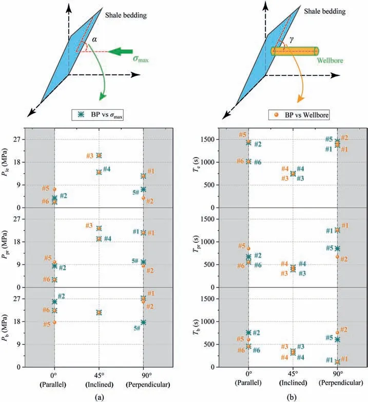
Fig.5.Different pressure levels(a)and corresponding times(b)in hydraulic fracturing tests of Lushan shale versus the angle of shale bedding with respect to the maximum in situ stress (α,BP vs.σmax) and the wellbore orientation (γ,BP vs.wellbore).
As for the times during hydrofracturing process (Fig.5b),the breakdown time decreases monotonically with the increase of the anglesα(BP vs.σmax) andγ(BP vs.wellbore),while the fracture propagation time and effective injection time both display a first decrease and then increase and reach their minimum values as the maximum in situ stress (or wellbore orientation) is applied at 45°oblique to the shale bedding plane.
Note that the investigated pressure and time (exceptTe) values are significantly different even if the angle(αorγ)is the same.For instance,the two breakdown pressures atγ=90°are very close(~27 MPa,Fig.5a),but significant contrasts are recorded in the fracture propagation pressure,lowest pressure,and breakdown time.A possible explanation for this phenomenon may result from the pre-existing natural fractures,which will drastically lower the pressure resistance for fracture initiation and propagation(Zoback et al.,1997;Tan et al.,2020).
3.1.2.Displacement response
As previously shown in Fig.4,an apparent variation in displacement is primarily observed upon sample breakdown.This is attributed to the initiation or closure of the induced fractures,which causes the sample to expand or contract in certain directions(Zhao et al.,2022b).In addition,the variation in displacement is generally concentrated near the drop of fluid pressure,indicating a consistent response between the fluid pressure and sample displacement for new fracture initiation.In sample#4(Fig.4d),an abnormal phenomenon is observed;the displacement attenuation lags behind the pressure drop by 175 s after two pressure peaks.This is presumably related to the incomplete failure of sample#4 in stages I-III,where fracture initiation,opening,closing and slippage can still occur after the breakdown.This may maintain the sample deformation within a certain fluctuation range.But after the sample is completely fractured,the fluid injected continuously can directly flow into induced fractures and leak out of the sample.Afterwards,closure of induced fractures by ambient stress will allow the compaction of rock,thereby resulting in the reduction of the displacement in sample #4.
3.2.Hydraulic fracture morphology
3.2.1.Qualitative analysis based on observed fracture path
As indicated in Table 1,the morphology of hydraulic fractures has been divided into a single bi-wing hydraulic fracture and multiple hydraulic fractures.Fig.6 further displays the corresponding fracture reconstitution sketches,trajectory unfolded in theX-Zplane and propagation modes,in which red planes represent BF (bedding failure),blue planes represent NF (natural fracture),and green planes represent HF(hydraulic fracture).Similar to previous studies(Zhou et al.,2008;Zhang et al.,2019b),three types of fracture interactions (penetration,deflection and termination)between the HF and the natural discontinuities(e.g.NF and BP)are observed in Lushan shale.For the convenience of analysis,some symbols are introduced to distinguish the type of fractures on the unfolded sample surfaces.Fractures formed by cracking the shale matrix are named main hydraulic fractures MFi,andirefers to the fracture number.The hydraulic fractures (HF) are represented by HFi,and the natural fractures (NF) activated by fluid injection are denoted as NFi.With this terminology,the potential dynamics of the four types of fractures can be characterized as follows (Fig.6,sketches on the right).
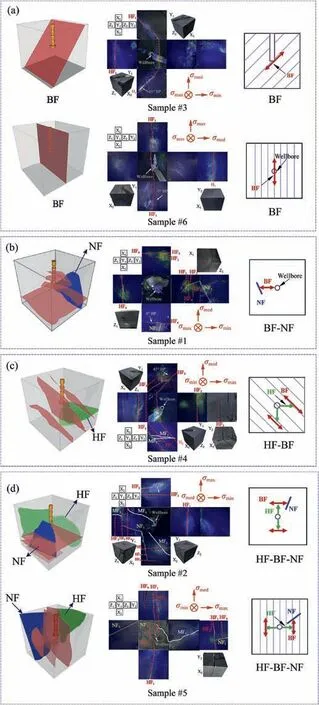
Fig.6.Fracture reconstruction sketches (left,rock cube with color planes),the trajectory unfolded in the X-Z plane(middle,six cube faces)and synoptic figures showing potential propagation modes (right,squares with red arrows) of the four types of fractures: (a) Bedding fracture (BF),(b) Bedding fracture interacting with natural fracture(BF-NF),(c)Hydraulic fracture interacting with bedding fracture(HF-BF),and(d) Hydraulic fracture first interacting with bedding fracture and subsequent with natural fracture (HF-BF-NF).
(1) Type 1 fracture: BF,single fracture created by opening a bedding plane (Fig.6a,BF).In both samples #3 and #6,the hydraulic fracture nucleates and propagates along a bedding plane.Although the hydraulic fracture is slightly curved near the laminar surface (probably due to the contrasts in the bonding properties between adjacent bedding planes),the main direction of fracture remains constant,and no other fractures are visible on the analyzed surfaces.The main cause of BF-type fractures can be attributed to the orientation of maximum principal stress subparallel to the shale bedding.This facilitates the activation of BF.
(2) Type 2 fractures: BF-NF,multiple activated bedding planes coalescing with natural fractures (Fig.6b).Bedding planes have a weak cementing strength compared to the shale matrix.Therefore,multiple fractures can initiate at the borehole wall once the fluid pressure is increased (Fig.6b),bedding fractures HF1,HF2,HF3and HF4).During the propagation of BF(Fig.6b),unfold surfaces of sample#1,a natural fracture (NF1) adjacent to the wellbore will arrest (HF3and HF4),or will alter the initial fracture propagation direction(HF1and HF2).
(3) Type 3 fracture: HF-BF,multiple hydraulic fractures coalescing with bedding planes(Fig.6c).Following the direction of maximum in situ stress,first,two hydraulic main fractures(MF1and MF2) initiate.The main fractures deflect into bedding planes,forming multi-parallel fractures HF1,HF2and HF3.Different cracking degrees of the activated bedding plane result from the highly developed microcracks near the open hole section,the inclination of the maximum in situ stress relative to the bedding plane,and the local heterogeneous cohesion strength of the bedding planes.
(4) Type 4 fractures: HF-BF-NF,multiple matrix fractures first,coalescing with the bedding planes and subsequently,activating natural fractures (Fig.6d).With the increase of fluid pressure,main fractures first initiate near the wellbore wall(samples #2 and #5).During this process,the main HF may encounter bedding planes and natural fractures,which cause the propagation to deflect into BP and NF directions.Compared with the type-3 fractures (HF-BF),when the HF propagates along the BP,randomly distributed NFs (NF1in samples #2 and #5) are encountered,and some parallel secondary fractures can be induced in different BPs,thus forming a complex,nonplanar and interconnected fracture network.
From Fig.6,we see that fracture morphology is predominantly affected by the maximum principal stress and bedding direction.A natural fracture can either arrest(obstacle)or branch the hydraulic fracture (bifurcation),thereby impacting the final geometry and morphology of fracture networks.When both bedding planes (BF)and natural fractures (NF) are involved,the resulting fracture networks created an increase in complexity compared to the case of only one factor involved.
3.2.2.Fracture orientation distribution and stimulated rock area
A polar diagram with origin in the wellbore centre (Fig.7) is used to display fracture orientations.We follow the method suggested by Taleghani and Olson (2014) and Ezati et al.(2020) to display our data from tracer analysis of Lushan shale.The distribution angle between the induced fracture and maximum principal in situ stress (σmax) is defined asβ.The sign ofβis assumed to be positive in the clockwise direction.
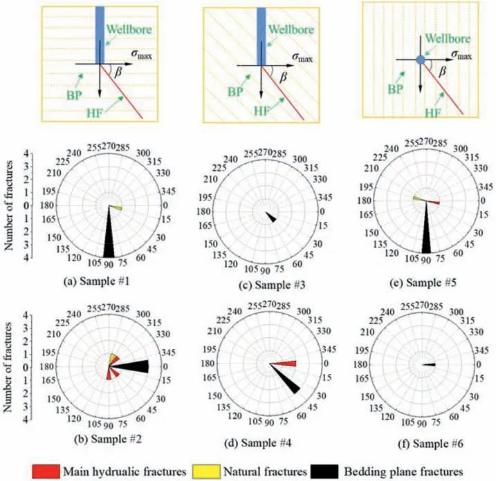
Fig.7.Rose diagram of induced fractures in the corresponding samples.The unit for the numbers around the circle is in degree.
Several conclusions can be drawn from Fig.7.First,the simple bedding plane fracture (BF) only occurs in the case of the bedding plane non-orthogonal to theσmax.Orthogonal stress conditions with respect to bedding planes are conducive to the formation of multiple fractures (e.g.BF-NF in sample #1 and HF-BF-NF in sample #5).Second,the main hydraulic fractures are not strictly consistent with the direction ofσmax,especially when they encounter the natural fracture and bedding planes.The main fractures act as a secondary factor in forming multiple hydraulic fractures.Third,the activation of bedding planes and natural fractures both help to increase the number of fractures and fracture branching.
We follow the approach of Hou et al.(2014) to analyze the stimulated rock area(SRA)in our shale samples after the fracturing experiment.As shown in Fig.8,there is an overall good correlation between the SRA value and the number of hydraulic fractures.Samples with a single bi-wing fracture(BF)have the lowest number of fractures and smallest fracture area.Relatively greater number of fractures and SRA are obtained when an HF growing normal to the BP or a natural fracture is activated during the hydrofracturing process.As the interaction of bedding planes and natural fractures both contribute to the fracture formation process(i.e.fracture type HF-BF-NF),larger number of fractures and stimulated areas are observed,which further confirms that the preexisting bedding planes and natural fractures are conducive to increasing the fracture area(Fig.8,samples #2 and #5).
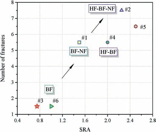
Fig.8.Number of fractures versus stimulated rock area (SRA) in tested Lushan shale samples.Large fracture numbers and large SRA values indicate favorable fracture network conditions in shale gas fracturing operations.Samples#2 and#5 develop the most suitable networks for efficient shale gas extraction.
Fig.9 shows the number of fractures and the SRA for different angles of the BP relative to theσmaxand the wellbore orientation.The largest contrasts,both in the number of fractures and SRA,are observed in the case when the maximum in situ stress and the wellbore are horizontal to the bedding plane.The alignment ofσmaxand BP direction is usually beneficial to form BF with simple fracture morphology.However,our results demonstrate that multiple HF-BF-NF fractures can also be observed in the situation where the BP direction is parallel with theσmax-direction.In the case of BP perpendicular to theσmaxand/or the wellbore orientation,the contrasts become smaller,and more fractures and larger SRA are observed,which illustrates the advantage of the orthogonal intersection case in creating complex fracture networks.
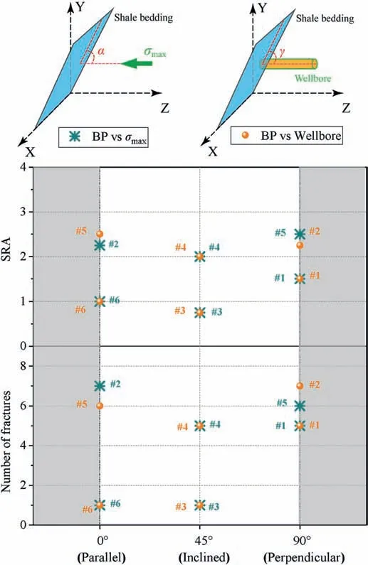
Fig.9.Number of fractures and SRA versus the angle of shale bedding with respect to the maximum in situ stress (α,BP vs.σmax) and the wellbore orientation (γ,BP vs.wellbore).
4.Discussion
4.1.Impact of bedding planes
Cylindrical specimens are frequently used in previous triaxial hydraulic fracturing tests (σ2=σ3),and their breakdown pressure changes considerably with increasing bedding plane angle(i.e.the angle between theσmaxand the direction normal to the bedding plane in line with Lin et al.,2017).As shown in Fig.10,Lin et al.(2017) and Guo et al.(2021) show that the breakdown pressure of the cylindrical sample decreases with the increase of the bedding plane angle.Using cubic specimens of larger size(200 mm×200 mm×200 mm)and true triaxial stress conditions,this study indicates that the breakdown pressures in the case with the angle of 45°are on average close to the case with 0°.Chen et al.(2021)observed a similar phenomenon between the 0°angle case(Pb=15.77 MPa)and the 90°angle case(Pb=16.41 MPa)in shale samples with an identical size and similar stress conditions like in our study.Thus,lower breakdown pressures are observed in larger cubic samples as compared to the cylindrical specimens.A reason for this may be that bedding planes and/or natural fractures are more abundant in a relatively larger volume of a rock sample compared with a smaller rock volume.Higher density of weakness planes results in a lower breakdown strength value of the shale specimens.Moreover,higher breakdown pressures are both obtained in the case of horizontal bedding and inclined(45°)bedding,especially when the wellbore axis and maximum stress align.The misalignment of maximum stress and borehole orientation leads to higher breakdown pressure in terms of an identical sample size.

Fig.10.Comparison of sample geometry effects on breakdown pressure versus bedding plane angle and wellbore orientation under the normal faulting stress regime.
Different orientations of bedding planes change the stress distribution around an approaching hydraulic fracture (Zhang et al.,2020).Fracture propagation normal to the bedding typically causes activation of the bedding plane close to the fracture tip.This creates a more tortuous fracture path by branching fractures deflected into bedding planes (samples #1 and #5,Fig.6).The opening of the bedding planes is restrained in the direction perpendicular to the maximum stress.Taking sample #1 as an example,we find four hydraulic fractures of varying lengths(H1,H2,H3and H4) nucleating from the open hole section of the wellbore.Increasing bedding plane angle results in lower normal stress components within the horizontal bedding planes (Table 1 and Fig.10),which causes a hydraulic fracture easy to arrest and difficult to cross the bedding plane.In Fig.8,the number of fractures and SRA of samples(#1,#2 and#5)with 0°BP are generally larger than those of 45°BP (#3 and #4),which indicates that a more complex fracture network is created in formations with horizontal bedding planes compared with the case of inclined bedding planes.The experiments conducted by Anderson (1981),Li et al.(2016b) and Guo et al.(2021) support this conclusion.
4.2.Effect of in situ stress
During the hydrofracturing process,the initiation and propagation of hydraulic fractures gradually deviate from the maximum in situ stress (Fig.6c and d,samples #2,#4 and #5).Compared to the fractures in the normal faulting stress regime (Fig.6b,sample#1),more branches and larger fracture areas are generated in the strike-slip stress regime (sample #2,Fig.6d),which is in line with the observation of Zhou et al.(2008) in homogenous material.In the case of horizontal well fracturing,more complex fracture networks(HF-BF-NF)are formed in the normal faulting stress regime(sample #5,Fig.6d),while a relatively simple BF geometry is observed in the strike-slip stress regime (sample #6,Fig.6a).This observation contradicts the findings of Zhou et al.(2008) who reported that hydraulic fractures could easily become tortuous in a strike-slip stress regime.This is because the rock and pre-existing fractures in Zhou et al.(2008) are simulated by analog rock material made from cement mortar blocks and different thicknesses of paper,respectively,which could not reflect the layered structure and bedding anisotropy of shale reservoirs.In addition,the different mechanical properties of the fabricated fractures in Zhou et al.(2008) as compared to the natural bedding planes in current study might also contribute to this inconsistency.As the wellbore is oriented horizontally,the stress state around the open-hole section may change significantly (compared to the case of the vertical wellbore),which may be the cause of different fracture geometries.
Moreover,the stress difference also plays an important role in affecting the bifurcation and tortuosity of hydraulic fractures(Huang and Liu,2017;Osiptsov,2017).Relatively low horizontal stress difference (Δσ=3 MPa) can increase the instability of bedding planes and create a simple fracture under strike-slip conditions.In the true triaxial hydraulic fracturing tests conducted by Guo et al.(2014),a similar strike-slip stress regime(i.e.σv:σH:σh=3:4:2)was applied.The results indicate that the BFs are easy to form during hydraulic fracturing as the stress difference between the overburden pressure (σv) and the minimum horizontal in situ stress(σh) is 3 MPa.Therefore,when the vertical in situ stress difference is low and the bedding plane is fully developed,the influence of the strike-slip stress regime could be shielded,resulting in simple BF morphology.
4.3.Influence of wellbore orientation
The breakdown pressures of vertical well hydraulic fracturing(27.27 MPa,25.85 MPa and 21.62 MPa for samples #1-#3) are generally higher than those of the horizontal well (21.51 MPa,17.69 MPa and 22.36 MPa for samples #4-#6).These results confirm the speculation of Guo et al.(2021) who compared the breakdown pressures of horizontal and vertical well fracturing under the premise of ignoring sample size.
Moreover,the number of fractures and SRA of the vertical wellbore (sample #1) are 1.5 and 5,respectively,which are lower than those (2.5 and 6) of the horizontal well (sample #5).Thus,horizontal wellbores are more conducive to creating complex fracture networks with more branches and larger fracture areas.A similar phenomenon can also be identified in samples #3 and #4,which further demonstrates the advantages of the horizontal wellbore in inducing complex fracture networks over the vertical wellbore under the normal faulting stress state.A reason for more complex fracture networks caused by horizontal boreholes is given in the next section.
4.4.Combined effects of stress,bedding plane and wellbore orientation
During field hydraulic fracturing,if the direction of the principal stresses deflects or the fracturing operation is deployed by vertical or horizontal boreholes,the impact of bedding inclination will be largely disturbed.This is a result of stress redistribution due to the existence of the wellbore and alternation of the principal stress direction (Fallahzadeh et al.,2015).Thus,focusing merely on the bedding inclination relative to the horizontal direction cannot guarantee a reliable estimation of shale breakdown pressure and fracture morphology.More attention should be paid to the inclination of bedding planes with respect toσmaxand wellbore orientation.
4.4.1.Mutual impact of bedding inclination relative to the effects ofstress regime and wellbore orientation on reducing breakdown pressure
The bedding inclination parallel toσmaxand wellbore orientation both help reduce the breakdown pressure(Fig.5a).By contrast,the wellbore orientation has a more significant effect on the breakdown pressure than the maximum in situ stress.To further verify these inferences,we compared our results to previously published data on shale in Fig.11.The breakdown pressures present an overall increasing trend with the increase of bedding inclination with respect to the maximum stress and the wellbore orientation,regardless of stress states and properties of the fracturing fluid.It should be noted that the properties of hydraulic fracturing fluid also play a crucial role in reducing shale breakdown strength.Both SC-CO2fracturing and LN2fracturing result in lower breakdown pressure and more productive fracture network than that of waterbased fracturing (Bennour et al.,2018;Kalam et al.,2021),which are attributed to the deterioration of rock strength caused by fluid diffusivity of SC-CO2or thermal shock of cryogenic LN2.Nevertheless,the similar build-up trend of breakdown pressure under identical fracturing fluid still illustrates the feasibility of achieving low breakdown pressure by adjusting the bedding inclination parallel toσmaxand/or wellbore orientation.The individual fracturing mechanism for different injection fluids,which is not discussed in the present study,will be considered as a focus in future studies.
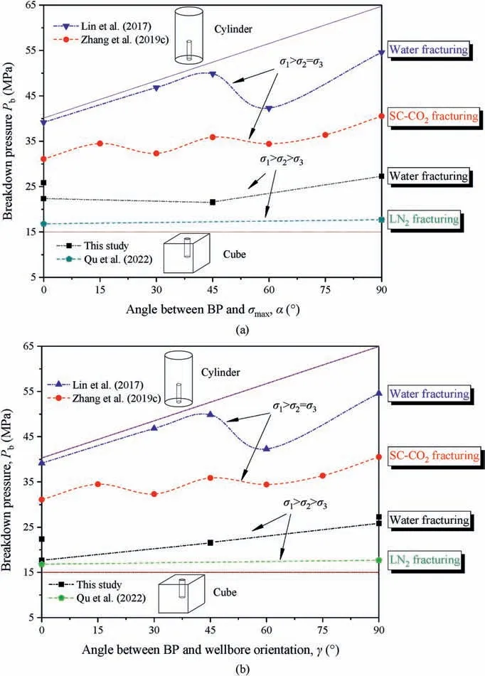
Fig.11.Comparison of breakdown pressures from this study and previous work(Lin et al.,2017;Zhang et al.,2019c;Qu et al.,2022).BP with respect to(a)stress direction,and(b)wellbore orientation.SC-CO2 and LN2 are the abbreviations of supercritical carbon dioxide and liquid nitrogen,respectively.
Moreover,under the normal faulting stress state,as a wellbore is arranged horizontally (aligned with bedding inclination),the breakdown pressure of the sample with 0°bedding will decrease from 27.27 MPa to 17.69 MPa (decreased by 35.1%),while the breakdown pressure of the sample with 45°bedding will decrease from 21.62 MPa to 21.51 MPa (decreased by 0.5%).A similar tendency has also been observed in cylindrical samples with a size ofϕ50 mm×100 mm as previously shown in Fig.10 according to Guo et al.(2021).Therefore,the effects of wellbore orientation on breakdown pressure decrease with the increase of bedding inclination under the normal faulting stress state.
4.4.2.BPs altering the mechanically preferable pathway of HF
As the mechanically preferable direction of HF (alongσmax) coincides with the bedding orientation,it is usually expected to produce a typical planar bedding fracture (Tan et al.,2020;Guo et al.,2021),as schematically shown in Fig.12a.The simple biwing bedding fracture in sample #6 (Fig.6a) further confirms this conclusion.On the other hand,the misalignment of the maximum stress with the bedding inclination could alter the mechanically preferable pathway of hydraulic fractures (Fig.12b).Typically,the shale bedding plane has a smaller tensile strength than that of the rock matrix,which is more likely to facilitate the nucleation and initiation of hydraulic fractures near the wellbore(Tan et al.,2017).Upon fracture initiation,the fluid pressure gradient needed to extend along the bedding plane is relatively low compared to that for new fracture initiation along theσmax.In turn,the bedding inclination becomes the preferential fracture pathway and will dictate subsequent fracture growth,which makes the main fracture to deviate from the principal stress direction (e.g.sample #3 in Fig.6a).A similar characteristic of HF activating a single bi-wing BF not aligned with the principal direction was observed in the largescale true triaxial fracturing tests of Longmaxi shale samples (Tan et al.,2020).The experimental work reported by Huang and Liu(2017) also demonstrated that the bedding plane effect prevented the hydraulic fractures from extending along the principal direction and prompted the hydraulic fractures to extend along the bedding plane.
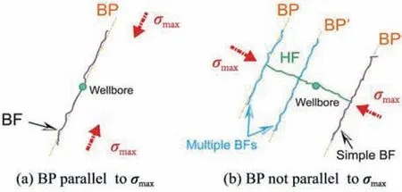
Fig.12.Schematic diagram showing fracture growth under the case of (a) bedding plane parallel to σmax,and (b) bedding plane perpendicular to σmax.
Our results indicate that the hydraulic fractures will deflect from the principal stress direction by forming multiple bedding fractures near the borehole wall(Fig.6d,sample#2).Manchanda et al.(2019)numerically simulate the creation of a multi-stranded fracture network on the reservoir scale.They revealed that multi-stranded fracture growth can be created in the reservoir as long as material properties are heterogeneous.On this basis,we can infer that the formation of multiple bedding planes in sample #2 is likely to be associated with the bedding heterogeneity in the vicinity of a wellbore that may facilitate multiple bedding planes to be simultaneously opened during the fracturing process.
Therefore,the activation of bedding planes in shale is the main cause of HF propagating in a direction deviating from the principal stresses.Multiple activations of bedding fractures can be created under the combined effects of bedding heterogeneity and maximum principal stress.
4.4.3.Dominating effects of relative orientations of wellbore,bedding and stress on the complexity of fracture networks
Adjusting theσmaxnormal to the bedding plane (i.e.normal faulting stress regime) facilitates the formation of complex fractures with a large stimulated area(Fig.9).Under a normal faulting stress regime,the SRA of the fracture network decreases by 50%when the bedding orientation increases from 0°to 45°(samples#1 and #3).However,as the wellbore is deployed horizontal to shale bedding (samples #4 and #5),only a 20% reduction in SRA under the same normal faulting stress regime.This illustrates that the horizontal wellbore can enhance the effects of the bedding orientation on inducing complex fracture networks.
Fig.13 compares the variation of the fracture complexity versus wellbore orientation with respect to bedding inclinations.For convenience,the fracture complexity index is rescaled into a range of [0,1] following
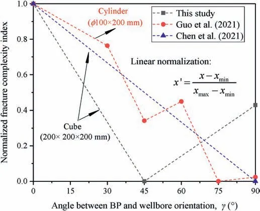
Fig.13.Comparison of fracture complexity data from this study with previous work in case of wellbore orientation perpendicular to the maximum principal stress.
wherex′is the linearly-normalized index,xis the measured index,xmaxis the maximum index,andxminis the minimum index.The results further demonstrate that deploying the wellbore axis subparallel to BP is beneficial to the formation of complex hydraulic fractures.
The relatively low breakdown pressure mentioned in Section 4.3 and the complex fracture morphology in the case of the wellbore parallel to BP result from the different effective areas projecting on the bedding plane,as observed in Fig.14.The horizontal wellbore has a larger surface area in contact with the target formation.This means less area of the bedding plane is available to sustain the fluid pressure,and as a consequence,bedding planes are easier to activate during the hydraulic fracturing process.Field-scale fracturing of the Marcellus Shale reservoir also demonstrates the advantage of horizontal drilling and its potential for a greater reservoir volume and increased flow of hydrocarbons into the well (Arthur et al.,2008).These explanations qualitatively illustrate why lower breakdown pressure and more complex fracture networks are created during horizontal well fracturing.Quantitative evaluation of this effect is out of the analytic scope of this study but is recommended to be investigated in further research.
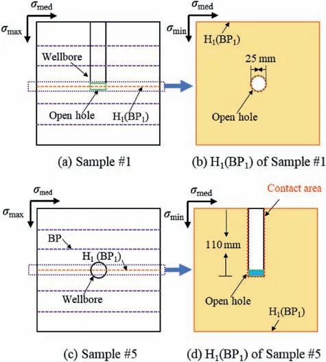
Fig.14.Comparison of the influence of wellbore orientation on hydraulic fracturing process.
4.5.Field implications
Laboratory experiments provide evidence for understanding shale failure mechanism during the hydraulic fracturing process.Natural shale samples represent the complexity of reservoir rock such as bedding planes and joints.However,laboratory testing also faces limitations.First,this is the upscaling of results from small laboratory samples to field operations,and second,this is the limited number of test cases involved,and associated uncertainties.On one hand,a laboratory specimen is usually too small to reflect the overall physical breakdown process,i.e.fracture nucleation,propagation and arrest.On the other hand,increasing sample size will result in difficulties in preparing and machine-testing samples.We admit that more test sequences with different bedding inclinations are required to build confidence on the hydraulic fracture results obtained on Lushan shale in this study.An in-depth analysis of hydraulic fracture dynamics can be further supported by using indirect in situ methods to characterize fracture growth and fracture source analyses like quantitative acoustic emission measurements.
Assuming the 200 mm rock cubes as representative volume elements for Lushan shale formations,we can obtain several field implications.First,when designing hydraulic fracturing in the deep shale formation,it is vital to fracture the laminated reservoir with low breakdown pressure.Based on the findings above,it is suggested that the wellbore deployed in the direction of bedding planes is beneficial to achieving low fracture pressures(Pb,PleandPpr).However,a bedding plane near the wellbore and low-stress difference (Δσ<3 MPa) can largely simplify the geometry of fracture networks,especially in the strike-slip stress regime(i.e.the direction of maximum principal stress aligns with bedding planes).When implementing the effects of wellbore orientation to stimulate shale reservoirs,we see it beneficial to determine the stress regime and bedding plane distribution,in particular,in the nearfield of the wellbore.Second,to avoid the formation of simple BF,an adjustment of the maximum principal stress normal to bedding planes may be required before the fluid injection starts.In summary,we recommend to quantify the spatial geometry of the wellbore,bedding plane and in situ stress,and to incorporate this near-wellbore geometry into the geological model of Lushan shale reservoirs.This certainly will improve hydraulic fracture initiation and propagation geometry,and the productivity of shale gas reservoirs.
5.Conclusions
Previous study mainly focuses on the independent effect of in situ stress,borehole orientation and bedding inclination.In this paper,we conducted true triaxial hydraulic fracturing experiments to investigate the mutual effects of the three factors on fracturing effectiveness under different stress states,bedding inclinations and wellbore orientations.The evolution of fluid pressure and displacement during the hydraulic fracturing process was analyzed and interpreted.Reconstruction of induced fractures from fluid tracer analysis allows to obtain information on fracture network morphology like orientation distribution and stimulated rock area.The combined effects of the three factors on breakdown pressure and fracture morphology were discussed.The main conclusions are drawn as follows:
(1) The fluid pressure curves of Lushan shale follow four stages.Notable pressure changes are observed in the second rapid pressurization stage(II)and the fourth pressure stabilization stage(IV)due to the initiation,propagation,and arrest phase of hydraulic fractures,while significant changes in sample displacement are generally observed in the breakdown process.The pressure drop after breakdown indicates a fluid loss associated with the opening of fractures and the increase in permeability.
(2) The fracture morphology of Lushan shale is divided into four types: bedding plane fractures (type 1,BF),bedding planes coalescing with natural fractures (type 2,BF-NF),hydraulic fractures coalescing with bedding planes (type 3,HF-BF),and matrix fractures first,coalescing with the bedding planes and subsequent,activating natural fractures(type 4,HF-BFNF).Bedding plane fractures have the simplest geometry,whereas activation of bedding planes and natural fractures will greatly increase fracture bifurcation and fractured area.
(3) If the wellbore and/or the maximum in situ stress is oriented parallel to the bedding plane,the breakdown pressure is reduced.Compared to the in situ stress,the wellbore orientation has a more significant effect on the breakdown pressure reduction.The reduction effect is tapered with steeper inclination of bedding planes.
(4) Bedding planes can alter the otherwise stress-driven preferential pathway of hydraulic fractures,and form a relatively simple fracture morphology due to its low strength.Multistrand bedding fractures can be observed due to the combined impact of bedding heterogeneity and maximum principal stress.The wellbore axis subparallel to BP is beneficial to enhance the effects of the bedding orientation on inducing complex fracture networks.This is attributed to the relatively larger surface area in contact with the bedding plane in the case of horizontal wellbores compared to the case of vertical wellbores.
(5) When performing hydraulic fracturing in deep shale formations,it is suggested to drill wellbores in the direction of bedding planes to achieve lower breakdown pressures.To produce massive volumetric fractures,it is beneficial to adjust the maximum in situ stress normal to or the wellbore parallel to bedding inclination.Local activation of bedding planes,however,should be avoided,for example,by geological structure detection techniques before fluid injection starts.
Declaration of competing interest
The authors declare that they have no known competing financial interests or personal relationships that could have appeared to influence the work reported in this paper.
Acknowledgments
This research was supported by the National Natural Science Foundation of China (Grant Nos.52064006 and 52004072).It was also supported by the program(Grant No.202006050112)of China Scholarship Council (CSC) for the first author’s visit at the Helmholtz Centre Potsdam,GFZ German Research Centre for Geosciences.
List of symbols
σvVertical in situ stress
σHMaximum horizontal in situ stress
σhMinimum horizontal in situ stress
ΔσStress contrast
Ax0Displacement components inX-axis direction at the beginning of the fracturing tests
Ay0Displacement components inY-axis direction at the beginning of the fracturing tests
Az0Displacement components inZ-axis direction at the beginning of the fracturing tests
AxiDisplacement components inX-axis direction at a certain time during fluid injection
AyiDisplacement components inY-axis direction at a certain time during fluid injection
AziDisplacement components inZ-axis direction at a certain time during fluid injection
AxRelative displacements inX-axis direction during fluid injection
AyRelative displacements inY-axis direction during fluid injection
AzRelative displacements inZ-axis direction during fluid injection
PbBreakdown pressure
PlowestLowest fluid pressure
PpFracture propagation pressure
TbBreakdown time
TeEffective injection time
TpPropagation time
βAngle between the induced fracture and the horizontal plane
 Journal of Rock Mechanics and Geotechnical Engineering2023年12期
- Journal of Rock Mechanics and Geotechnical Engineering的其它文章
- The formation of orthogonal joint systems and cuboidal blocks: New insights gained from flat-lying limestone beds in the region of Havre-Saint-Pierre (Quebec,Canada)
- Numerical analysis of the effects of vesicle distribution characteristics on the engineering properties of volcanic rocks
- A hybrid attention deep learning network for refined segmentation of cracks from shield tunnel lining images
- 3D limit analysis of rock slopes based on equivalent linear failure criterion with tension cut-off
- Unloading-induced permeability recovery in rock fractures
- An open-end high-power microwave-induced fracturing system for hard rock
