Triaxial tension and compression tests on saturated lime-treated plastic clay upon consolidated undrained conditions
Kuchvichea Kan,Bertrand François
a Department of Civil Engineering,Institute of Technology of Cambodia,Phnom Penh,Cambodia
b BATir Department,Université Libre de Bruxelles,Brussels,Belgium
c ArGEnCo Departement,Université de Liège,Liège,Belgium
Keywords:Tensile strength Consolidated undrained (CU) triaxial test Lime-treated soils Failure criterion
ABSTRACT Lime-treatment of clayey soil significantly increases its shear and tensile strengths.Consequently,the tensile strength of lime-treated soils deserves careful investigation because it may provide an appreciable benefit for the stability of earth structures.This study investigates the tensile and shear strengths of an untreated and lime-treated(3%of lime)plastic clay at different curing times(7 d,56 d and 300 d),through triaxial tension and compression tests.Triaxial tension tests are performed using “diaboloshaped” soil samples with reduced central section,such that the central part of the specimen can be under axial tension while both end-sections remain in axial compression.Consolidated undrained (CU)conditions with measurement of pore water pressure allow analyzing the failure conditions through effective stress and total stress approaches.The results of triaxial tension tests reveal that the failure occurs under tensile mode at low confining pressure while extensional shear failure mode is observed under higher confining pressure.Consequently,a classical Mohr-Coulomb shear failure criterion must be combined with a cut-off tensile strength criterion that is not affected by the confining pressure.When comparing shear failure under compression and tension,a slight anisotropy is observed.
1.Introduction
In geotechnical constructions,the tensile strength of soils is very connected with the different tensile cracks that can be developed in earth structure such as retaining wall,slopes or embankment(Tang et al.,2019).Often a tensile crack can be observed at the top surface of earth structures as a sign of instability (Vaníček,2013).Tensile cracks may also occur due to tensile stresses induced by strainconstrained soil desiccation leading to significant reductions of the hydro-mechanical engineering properties of the soil (Morris et al.,1992;Konrad and Ayad,1997;Albrecht and Benson,2001;Peron et al.,2009;Tang et al.,2011).However,in practice,the tensile strength is neglected in most geotechnical stability analysis,leading to limited test data on the behaviors of soils in the negative effective stress range.Geotechnical engineers commonly adopt conventional triaxial compression tests data in design practices of earth structures,but ignore the tensile characteristics of the ground.
The tensile strength can be measured by direct,indirect(such as Brazilian test,also called splitting test)or bending method (threeor four-points bending test) (Al Houri et al.,2020).It is observed that those methods provide different values of tensile strengths for the same material under the same conditions.Namikawa and Koseki (2007) numerically demonstrated that the splitting tests underestimate the tensile strength because,under splitting conditions,shear failure may occur before tensile failure.Also,the bending tests overestimate the tensile strength because of stress redistribution around the tensile failure zone.Finally,they concluded that the direct tensile tests provide the most reliable value of actual tensile strength.Those under-and over-estimations of the tensile strength by splitting and four-point bending tests,respectively,were also observed experimentally by Araki et al.(2016).
Recently,most of the developed direct methods to measure tensile strength of soil are usually focused on uniaxial tensile test(e.g.Tang and Graham,2000;Nahlawi et al.,2004;Tamrakar et al.,2005;Lu et al.,2007;Lakshmikantha et al.,2012;Li et al.,2014;Tang et al.,2015;Wong et al.,2020;Salimi et al.,2021).This method is carried out by controlling the tensile loading or displacement without any confining pressure.However,those direct methods may appear complex in practice due to problems of specimen preparation and specimen clamping during tensile loading.Alternatively,the triaxial extension tests consist in reducing the axial load while keeping the radial confining stress as a constant,as conducted by Balasubramaniam and Waheed-Uddin (1977),Parry(1960) and Ignat et al.(2019).However,conventional triaxial extension tests with cylindrical specimen do not investigate the tensile strength because axial stress should be in the compressive range or be subjected to the detachment of the end caps from the specimen.Namikawa et al.(2017)reached axial tensile stress under triaxial conditions but had to use Gypsum as a filling material for the gap between the specimen and the holders to transfer tensile force during the loading process.
Bishop and Garga (1969) developed an original method to measure the tensile strength of the blue London clay by triaxial tension test.This method uses a sample with a reduced center section.The test takes place in a standard triaxial cell.After consolidation,the axial stress is decreased while maintaining a constant confining pressure,thus following a reduced triaxial extension path.Due to the geometries of specimen,a tensile effective stress develops in the center section while the end sections remain in compression.Both ends of the specimen are in compression,and thus it does not require any clamping system to attach the ends of the specimen to the loading system.By applying low confining pressure,the mode of failure is typical brittle fracture in tensile mode.It is also observed that upon increasing confining pressure,the failure mode passes from a tensile failure to an extensional shear failure.
Triaxial tension tests allow to measure the tensile strength in addition to the change in volume or pore pressure for consolidated drained (CD) or consolidated undrained (CU) tests,respectively.In addition,the tensile strength can also be measured at different confining pressures.This combination thus makes it possible to obtain a continuous failure criterion with a failure mode changing from pure tension to shear by extension.These failure modes depend on the confining pressure and the cohesion of the material.
Lime-treated soil is an efficient way to improve the mechanical characteristics of fine-grained soils with applications in road subgrades (Selvi,2015),hydraulic works (Makki-Szymkiewicz et al.,2015) or road and railway embankments (Celauro et al.,2012).Pozzolanic reactions between aluminates and silicates of the soil with lime form binding minerals that confer relevant soil mechanical properties such as a higher cohesion level (Makki-Szymkiewicz et al.,2015),reduction in swelling potential(Mrabent et al.,2016) or compressive and tensile strength (Bell,1996).With regards to tensile strength,Baldovino et al.(2018)demonstrated,through splitting tests,that lime-treatment may increase the tensile strength of a sandy clay by a factor of 3-8,depending on the lime content(from 3%to 9%)and the curing time(from 15 to 90 d).Consoli et al.(2012) observed similar trends on polypropylene-fibre-reinforced silt-lime mixtures.For limetreated soil,a proper measurement of tensile strength is thus of paramount importance in order to consider all the benefits of the lime-treatment in the geotechnical design of reinforced soils.
Lime-treatment provides valuable tensile properties to clayey soils but this benefit is weakly investigated experimentally,poorlydocumented and not considered in the design methods of geotechnical structures.Therefore,this paper provides an experimental investigation of tensile and compressive behaviors of a lime-treated clayey soil and integrates the tensile strength criterion into the conventional shear failure criterion.We combine triaxial compression and tension tests,conducted on a saturated untreated and lime-treated (3% of lime) clayey soil at different curing times(7 d,56 d and 300 d) in CU conditions,in order to evaluate the benefit of lime-treatment in terms of improvement of tensile and shear strengths.Firstly,the conventional properties of tested soils are presented,including grain size distribution,modified proctor curves and direct shear test results.Secondly,the specificities of triaxial tension tests are introduced,with a detail on the adaptation of a conventional triaxial compression apparatus to perform triaxial tension tests.Then,the stress-strain behavior and failure criterion,upon triaxial compression and tension tests,are presented successively.Finally,those failure criteria are compared to highlight the effect of lime treatment and the difference between shear strengths upon compression and extension.
2.Material properties
2.1.Quicklime
In this study,a quicklime CL 90-Q (EN 459-1,2015) from the Lhoist group was used.It has the following characteristics: (i)Particle sizes:99.98%<2 mm and 83%<80 μm;(ii)Available lime content:91.2%;and (iii) Reactivity:t60=4-6 min.
2.2.Unified soil classification system (USCS)
Fig.1 shows the grain size distribution curve of the studied soil.The soil counts 3%,67% and 30% of sand (>74 μm),silt (>2 μm,<74 μm) and clay (<2 μm) particles,respectively.The liquid limit and plasticity index are 55.3% and 29.5%,respectively.From USCS classification,this soil is of a highly-plastic clay(CH).
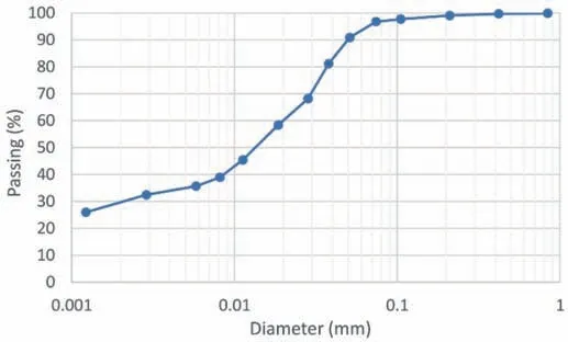
Fig.1.The grain size distribution curve of the studied soil.
2.3.Specimen preparation
The soil preparation consists in drying the wet soil at a temperature of 60°C and powdering it.The residual water content(of the soil dried at 60°C) is measured by heating a small sacrificial specimen at 105°C.This residual water content is considered in the subsequent addition of water to reach the target water content.This water addition is made by mixing the dry powdered soil in the mixing pan until the color appears uniform,and then is kept in moisture-proof re-sealable plastic bag for 24 h for a good homogenization of water content in the soil.For the lime-treated soil,the wet soil is finally mixed with required lime content (3%) and compacted after 1 h by an in-mold dynamic compaction under optimum modified proctor conditions.The lime-treated soil specimens are then covered with plastic wrap,aluminum foil and paraffin in order to isolate them from the atmospheric conditions(to avoid water evaporation) and then stored in a temperaturecontrolled chamber at 30°C during the different curing times(7 d,56 d or 300 d).
2.4.Modified proctor conditions
Fig.2 and Table 1 show the dry densities obtained after compaction through the modified Proctor test for untreated and lime-treated soils with 3% of lime.Lime-treatment reduces the maximum dry density(MDD)and increases the optimum moisture content (OMC),as classically observed by many authors (e.g.Hussain and Dash,2015;Negawo et al.,2019).

Table 1OMD and MDD.

Fig.2.Modified Proctor curves for untreated soil and soil treated with 3% of lime.
2.5.Direct shear tests
Shear box tests were carried out to obtain the shear strength parameters of the compacted soils,under untreated and limetreated conditions at curing time of 28 d.The cylindrical soil specimens (diameter of 60 mm and thickness of 20 mm) are prepared at the modified Proctor conditions.After preparation and installation in the shear box,the specimens are saturated (submerged during 48 h in water) and consolidated through the application of the vertical load (masses of 20 kg,40 kg and 60 kg,corresponding to vertical stresses of 69 kPa,139 kPa and 208 kPa)under drained conditions.CD strengths are established by simple shear testing at slow shear displacement rates of 0.1 mm/min,to guarantee drained conditions as recommended in ASTM D3080-04(2012) guidelines.
Fig.3 shows the variation of shear stress with shear displacement and highlights the peak failure for each shearing.Shear strength is significantly influenced by the lime-treatment.Results indicate that the shear stress increases with the increasing shear displacement and reaches a peak at around 2-3 mm of shear displacement in almost all the cases irrespective of normal stress and lime treatment.For post-peak response,lime-treated specimens exhibit significant softening together with dilatancy;while for untreated soil,dilatancy and softening are much less pronounced.Table 2 summarizes the obtained effective strength parameters,in terms of cohesion and friction angle at peak state.The corresponding failure lines are reported in Fig.4.

Table 2Effective cohesion and friction angle,obtained from CD direct shear test on untreated and lime-treated soil at curing time of 28 d.
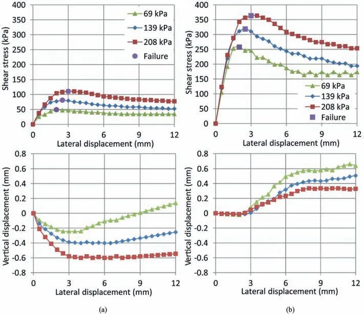
Fig.3.Shear stress and vertical displacement as a function of shear displacement during CD direct shear tests at 3 different normal stresses for: (a) Untreated soil,and (b) Limetreated soil (3% of lime,28 d of curing).
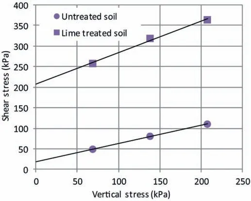
Fig.4.Failure lines obtained from drained direct shear tests at 3 different normal stresses on untreated soil and lime-treated soil (3% of lime,28 d of curing).
3.Triaxial tension tests
3.1.Goals and principles
Through the triaxial tension test framework,Bishop and Garga(1969) proposed a suitable method of extending the effective stress range under examination into the negative sector without the use of end clamps.A sample with a reduced central section,like a“diabolo shape”,creates an axial stressσadistribution divided in two main zones: the end-sections and the mid-section.
The diabolo-shaped sample,enclosed in a latex membrane sealed to the end caps (top and bottom caps),is submitted to a confining pressure (σr) in the three directions and a tensile axial force (T) in the vertical direction (as shown in Fig.5).
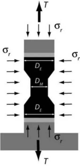
Fig.5.Geometry of the sample and applied stresses and forces for triaxial tension tests(DE is the diameter at end-section and DM is the diameter at mid-section).
According to static equilibrium equations,the axial stress at end-and mid-sections (σa,Eand σa,M) are
whereAEandAMare the areas of end-and mid-sections,respectively.In order to avoid detachment of both end caps from the specimen,it is required that the axial stress at end-sections remains positive,leading to a maximal axial tensile forceTmax=σrAE.Consequently,from Eq.(2),the limiting value of the axial stress of mid-sectionσa,M,limitis
whereDEis the diameter at end-section andDMis the diameter at mid-section.Consequently,the highest tensile stress that can be applied in the center of the specimen is reached for the largest diameter ratio.
A controlled strain rate tension test under constant confining pressureσrwill lead to a decrease of the axial stressσauntil the peak stress difference(σa-σr)is reached,unless the tensile stress(σa)exceeds the limit (σa,M,limit) given by Eq.(3).Tensile stress in this study is expressed as negative.For a sample with a central diameter of 19 mm and end diameter of 35 mm,as selected in study,we have
3.2.Diabolo-shape sample preparation
The usual procedure of sample cutting into a preferred shape is difficult to realize for lime-treated clay because of the brittleness of the sample that can crumble when it is shaped.So,samples have been manufactured by dynamic compaction in an aluminum mold with desired shape,as shown in Fig.6a.Samples are 35 mm in diameter at the ends,19 mm in diameter over the center section on a height of 20 cm for a total height of 70 mm.Two halves of aluminum mold were assembled and enforced by four screws.To make sure that the bottom part of sample has a density similar to the top part,two semi-rings were placed between the bottom of aluminum molds and the caps.The soil is first compacted with the two semi-rings from one side and then,as a second step,the semirings are removed and the compaction is completed.In such a way,after the removal of the semi-rings,the soil can be compacted from both sides simultaneously due to the top and bottom rammers that penetrate to the soil.
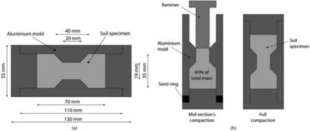
Fig.6.(a) Dimension of the diabolo-shaped mold and specimen,and (b) Compaction in two steps to ensure a better homogeneity of sample.
The first preliminary compaction was conducted on untreated clayey soil by filling total mass of sample into one compaction.After compacting sample to the desired volume,the sample was cut into three different parts (bottom,center and top).Total humid densities were measured and listed in Table 3.The density of central part was smaller than the density of extremity parts due to the reduced shape from the extremities to the center that decreases the efficiency of compaction in the center.

Table 3Wet bulk density of soil (g/cm3)in three zones of the diabolo-shaped sample.First trial by filling total mass of sample in one compaction.
The sample compaction procedure was then improved to ensure a better homogeneity of sample.Approximately 65%of total weight of soil was softly compacted over central part,as shown in Fig.6b.The top surface of the compacted soil was then scarified to increase the adhesion between the parts of soil.Then,the rest of soil was filled into the mold by covering the top cap and removing the semirings.After compacting sample into desired volume,the densities of sample were measured as shown in Table 4.This compaction procedure gave similar densities between center section and end sections.

Table 4Wet bulk density of soil(g/cm3)in three zones of the diabolo-shaped sample.Second trial by filling 65% mass of sample in the first compaction.
For untreated soil,by covering grease over the surface of mold before compaction,the compacted samples are successfully formed without observable cracks.In contrast for the lime-treated soil,because of the brittle state of lime-treated specimen,grease was not enough and during unmolding,the soil remained stuck to the two half molds and was hardly removable from the mold.So,a metal polish paste was used to paint over the molds before compaction.This makes the unmolding easier and did not create observable cracks on the sample.
3.3.Equipment and test procedure
Starting from a conventional triaxial apparatus,the carrying out of triaxial tension tests require a few adaptations.The sample is placed between two porous disks and is enclosed in a conventional latex membrane,dedicated to soil testing (0.3 mm thickness).The top cap was specifically designed to allow applying a proper pulling force on this cap(Fig.7).This top cap is made of Perspex with two flexible drainage connections.One drainage connection is used to saturate the specimen and to apply back-pressure while the other one is used to release air stored between the specimen and the membrane due to the specific diabolo-shape of sample.This top cap is connected to the stainless-steel ram which is built in T-shape to apply a tensile force and pull on the top cap to reduce the axial stress (initially equals to the confining pressure) applied on the specimen.
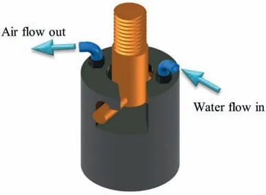
Fig.7.Homemade designed top cap to allow applying pulling force from the T-shaped piston,and permitting air flushing and water pressure applications from two flexible pipes.
The top cap is not attached with the steel ram in order to permit free movement of sample during saturation and consolidation.After completion of consolidation,the steel ram is vertically moved down into a slot in the top cap and is turned 45°to be in a position to engage the cap when a tensile axial displacement is applied.The tensile load is applied to the steel ram through a screw joint.The force is read automatically from a force transducer.
The cell is filled with water at an initial pressure of approximately 30 kPa to confine the air around the sample inside the latex membrane,while opening one drainage valve of the top cap to permit the air to flow out from the membrane.During this stage,a water pressure of 20 kPa is applied into the sample through another drainage connection.The water is transmitted from this connection through the top porous disk toward the de-air valve which is closed after water flows out.
The specimens are saturated by applying successive increments of pore pressure(Δu) and confining pressure(Δσr) of 40 kPa,until the pore coefficient (B) is nearly 95%.All along this process,the difference between confining pressure and pore water pressure is maintained at 10 kPa.At each increment of 40 kPa of confining pressure,Bvalue (Δu,generated/Δσr) is measured by increasing the confining pressure under undrained conditions.IfB<95%,the increment of 40 kPa of pore water pressure is applied and the drainage valve is opened.The next saturation step is applied when the injected water volume during the current step is less than 1 mm3/10 min.The sample is supposed to be fully saturated when the ratio ofB>95%.This procedure of saturation is applied for both triaxial compression and tension tests.
4.Results
4.1.Variable and sign convention
In this paper,the compressive stress and contractive strain are considered as positive while tensile stress and extension strain are negative.The deviatoric stress (q) is defined as the difference between axial and radial stress:
whereσais the axial stress andσris the radial stress.
Consequently,the deviatoric stress is negative upon triaxial tension tests because the axial stress becomes lower than the radial stress.The mean stress is the average between the three principal stresses:
For the triaxial compression tests,the axial stress (σa) is the major principal stress(σ1),while the radial stress(σr)is the minor principal stress(σ3);for triaxial tension tests,it is the opposite.
In both CU triaxial compression and tension tests,the failure condition is defined as the maximum of the ratio between axial and radial effective stress (σ′a/σ′r).If this ratio never reaches a maximum (peak value),the strength is considered at 15% of axial deformation.The strength parameters are determined by plotting the failure points in the triaxial plane(radial stress vs.axial stress)in both total and effective stress references.In that plane,the Mohr-Coulomb failure criterion yields:
wherecc/ecan be the cohesion in compression (cc)or in extension(ce) andφc/ecan be the friction angle in compression (φc) or in extension (φe).This criterion can be expressed in total or effective stress references,with respectivelyσ1,σ3,cc/eandφc/eexpressed in total stress reference orσ′1,σ′3,c′c/eandφ′c/eexpressed in effective stress reference.
The strength parameters are obtained from the best-fitting straight line passing through the failure point,expressed as
For triaxial tension tests,when the soil specimen experiences tensile failure,the failure criterion is a cut-off tensile strength criterion:
The tensile strength(σt)is expressed as a positive number,even if it corresponds to a stress state under tension.
4.2.Triaxial compression tests
The distortional behavior of the soil in compression was investigated by triaxial compression tests upon CU state.Untreated soils and soil treated with 3%of lime after 7 d,56 d and 300 d of curing were tested.The axial compression is controlled by imposing a constant displacement rate of 0.01 mm/min.The stress-strain and stress-pore water pressure behaviors are plotted in Figs.8-11,in terms of deviatoric stress vs axial strain and excess pore water pressure vs.axial strain,for untreated soils and lime treated soils after 7 d,56 d and 300 d of curing,respectively.
Fig.8 shows the stress-strain and stress-pore water pressure behaviors of untreated soil under four different confining pressures.The excess pore water pressure firstly increases with the axial stress,and then it decreases slowly,especially at low confining pressure.For lime-treated soils,Figs.9-11 reveal that soil strength and excess pore water pressure increase as a function of curing time and confining pressure.Also,the brittleness of the specimen (the tendency to produce a peak response followed by a decrease of pore water pressure,characteristics of dilatancy behavior) increases with increasing curing times and decreasing confining pressures.

Fig.9.Stress-strain and stress pore water pressure curves of CU triaxial compression tests of treated soils (3% lime) at 7 d of curing time at three different confining pressures (σr).
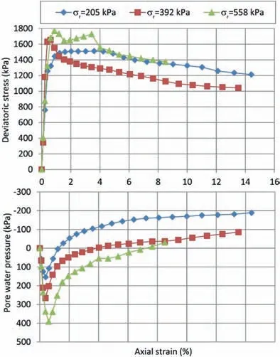
Fig.10.Stress-strain and stress-pore water pressure curves of CU triaxial compression tests of treated soils (3% lime) at 56 d of curing time at three different confining pressures (σr).
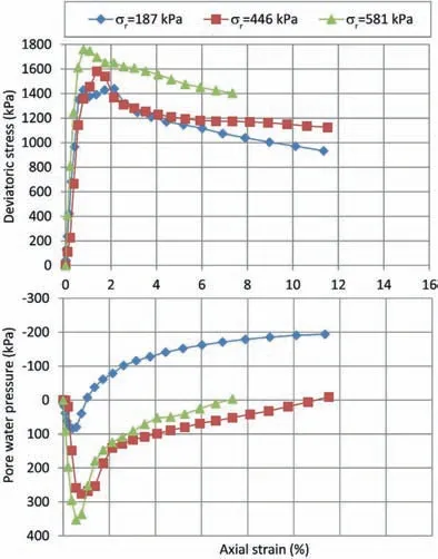
Fig.11.Stress-strain and stress-pore water pressure curves of CU triaxial compression tests of treated soils (3% lime) at 300 d of curing time at three different confining pressures (σr).
Fig.12 shows the stress paths and failure points in the triaxial plane(radial stress vs.axial stress)in both total and effective stress references for all the triaxial compression tests.

Fig.12.Stress paths,failure points and failure criteria,expressed in the triaxial plane(σr;σa)obtained during CU triaxial compression tests:(a)Untreated soil,(b)Lime-treated soil with 3% of lime at curing times of 7 d,(c) Lime-treated soil with 3% of lime at curing times of 56 d,and (d) Lime-treated soil with 3% of lime at curing times of 300 d.
The strength parameters are obtained from the best-fitting straight line passing through the failure point,according to Eq.(8) in both effective and total stress references.For triaxial compression tests,major principal stress(σ1)is the axial stress(σa)while the minor principal stress(σ3)is the radial stress(σr).Table 5 shows the obtained strength parameters.

Table 5Total cohesion and friction angle(φc and cc)and effective cohesion and friction angle(φ′c and c′c) deduced from CU triaxial compression tests.
The evolutions of cohesions and friction angles for untreated and lime-treated soils are plotted as a function of curing time in total and effective stress references (see Fig.13).Globally,both effective and total cohesions are increased with curing time(excepted a slight reduction of effective cohesion between 56 d and 300 d).Contrasted effect is observed for the effective and total friction angles for which no clear trend can be extracted.
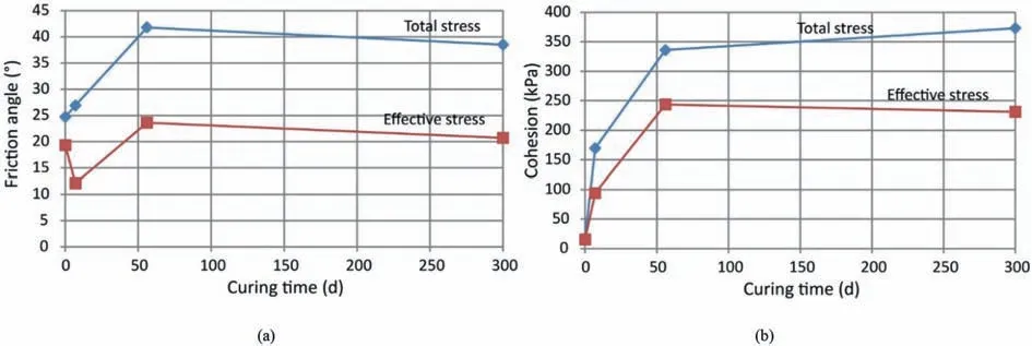
Fig.13.Evolution of total and effective strength parameters with curing time for CU triaxial compression tests: (a) Friction angle,and (b) Cohesion.
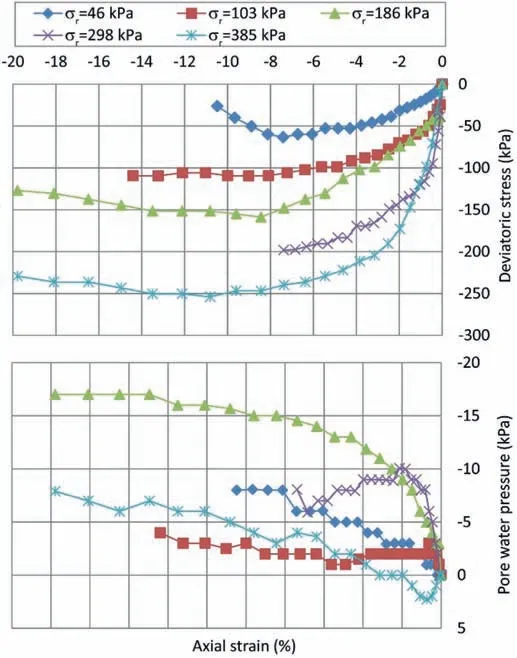
Fig.14.Stress-strain and stress-pore water pressure curves of CU triaxial tension tests of untreated soil at five different confining pressures (σr).
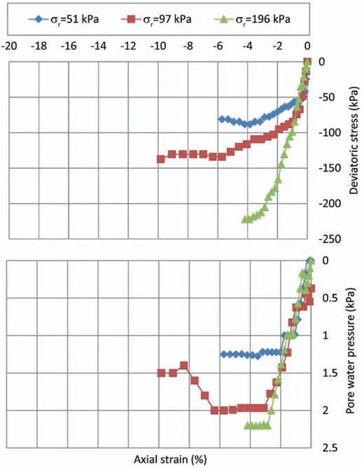
Fig.15.Stress-strain and stress-pore water pressure curves of CU triaxial tension tests of treated soils (3% lime) at 7 d of curing time at three different confining pressures(σr).
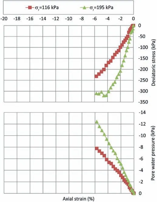
Fig.16.Stress-strain and stress-pore water pressure curves of CU triaxial tension tests of treated soils (3% lime) at 56 d of curing time at two different confining pressures(σr).

Fig.17.Stress-strain and stress-pore water pressure curves of CU triaxial tension tests of treated soils(3%lime)at 300 d of curing time at three different confining pressures(σr).
4.3.Triaxial tension tests
Triaxial tension tests were performed on untreated soils and treated soils with 3%of lime at 7 d,56 d and 300 d of curing under CU conditions.For each test,the axial extension is controlled by a constant displacement rate of -0.01 mm/min.For those triaxial tension tests,the same procedure of saturation and consolidation as that for triaxial compression tests was applied.The same criterion to determine the failure state,as the maximum of the ratio σ′a/σ′r,was considered.
For untreated soils,the focus was on both the tensile and shear failures.To do so,a wide range of confining pressures was applied in order to generate tensile failure,at low confining pressures and extensional shear failure at higher confining pressures.This was possible because the transition between tensile and shear failure occurs at relatively low confining pressures.On the contrary,for lime-treated soils,tensile failure mode occurs for a wider range of confining pressures (especially at large curing times).Consequently,only tensile failure was investigated,and cohesion and friction angle were not determined under extensional shear for lime-treated soil.
The stress-strain and stress-pore water pressure behaviors are plotted in Figs.14-17,in terms of deviatoric stress vs.axial strain and excess pore water pressure vs.axial strain,for untreated soils and lime-treated soils at 7 d,56 d and 300 d of curing,respectively.Globally,the ultimate deviatoric stress upon tension tests increases with the confining pressure while the excess pore water pressure evolves in a more disparate way.The magnitude of the excess pore water pressure is much lower than that for triaxial compression tests which may explain this disparate evolution of pore water pressure as a function of the confining pressure.
Fig.18 presents the values of tensile failure with the followed stress paths in the triaxial plane(σr,σa)in both total and effective stress references.The stress points start from the isotropic axis(σr=σa),while the axial stress is reduced,keeping the total radial stress constant until reaching failure.In effective stress reference,water pressure is subtracted from axial and radial total stresses to obtain effective stress.In this framework,failure can occur according to a shear mode or a tensile mode,as a function of the confining pressure.
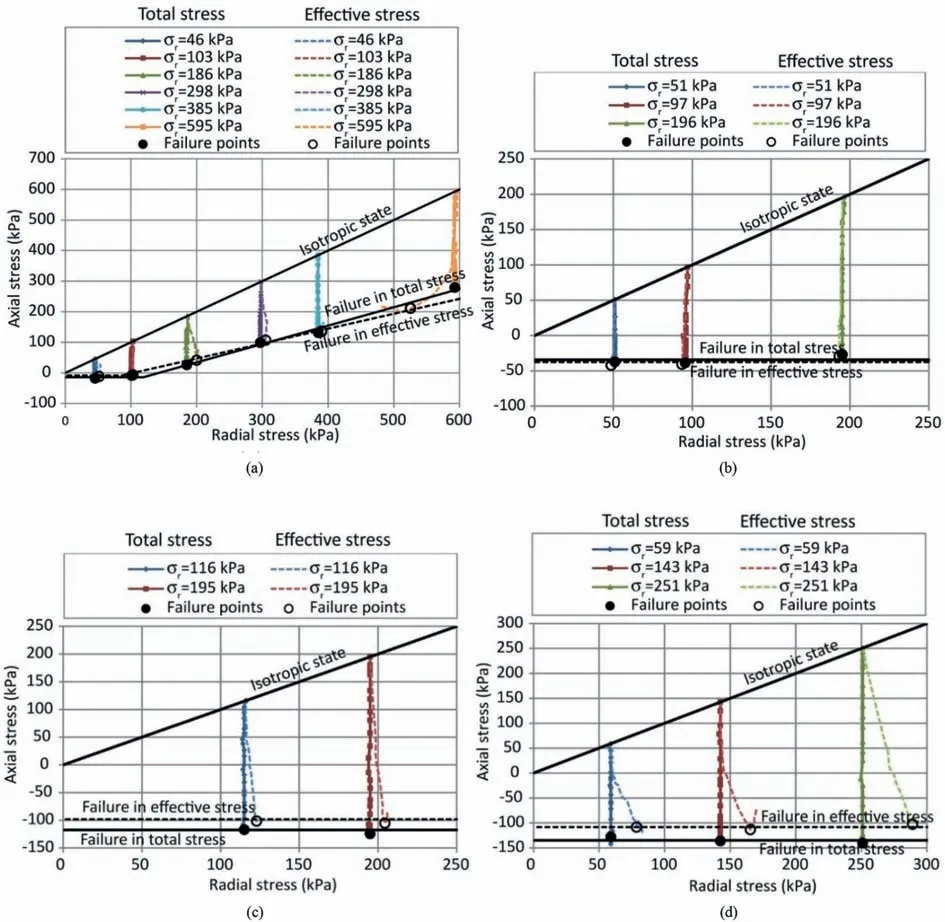
Fig.18.Stress paths,failure points and failure criteria,expressed in the triaxial plane(σr;σa)obtained during CU triaxial tension tests:(a):Untreated soil,(b)Lime-treated soil with 3% of lime at curing times of 7 d,(c) Lime-treated soil with 3% of lime at curing times of 56 d,and (d) Lime-treated soil with 3% of lime at curing times of 300 d.
For untreated soils,because of the large range of applied confining pressure,the two kinds of failure are observed leading to two combined failure criteria.σt=-σ3is proposed as a possible tensile failure criterion,while shear failure is classically represented by a Mohr-Coulomb criterion.At low confining pressure(i.e.50 kPa and 100 kPa),the axial stress at failure is in the tensile range(i.e.negative value) and the maximum reached values of tensile stresses correspond to the tensile strength cut-off criterion.As the confining stress increases (from 200 kPa to 600 kPa),the axial failure stress remains in the compressive range and the rupture points are following a Mohr-Coulomb shear failure criterion.
Following the same methodology than for triaxial compression tests,the shear strength parameters (ceandφe) are deduced from the best-fitting straight lines passing through the failure points according to Eq.(8).For triaxial tension tests,major principal stress(σ1) is the radial stress (σr) while the minor principal stress (σ3) is the axial stress(σa).In addition,a tensile strengthσtis defined as a cut-off criterion,according to Eq.(11).This is done in both total and effective stress references.
For treated soils,we limited the confining pressure to 200 kPa,such that the failure could exclusively occur upon tensile mode.This tensile failure stress is independent of the confining pressure and only depends on the curing time.This is characteristics of the cut-off tensile strength criterion that is known to be a constant value,whatever the confining pressure is.The higher the curing time and the higher the tensile strength,even if the strengths between 56 d and 300 d of curing are pretty much the same.
The obtained friction angle and cohesion for the Mohr-Coulomb shear failure criterion,as well as the tensile strength are given in Table 6,in both total and effective stress references.For treated soils,only tensile strength is given because of the low confining pressure that does not permit to reach the shear failure criterion.
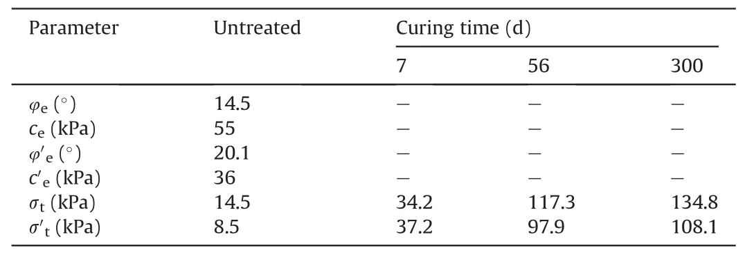
Table 6Total cohesion and friction angle (φe and ce),effective cohesion and friction angle(φ′e and c′e) and total and effective tensile strength (σt and σ′) deduced from CU triaxial tension tests.
The evolution of tensile strengths for untreated and treated soils are plotted as a function of curing time in Fig.19 in total and effective stress references.Globally,both effective and total tensile strengths are increased with curing time,with a trend to stabilize between 56 d and 300 d of curing.
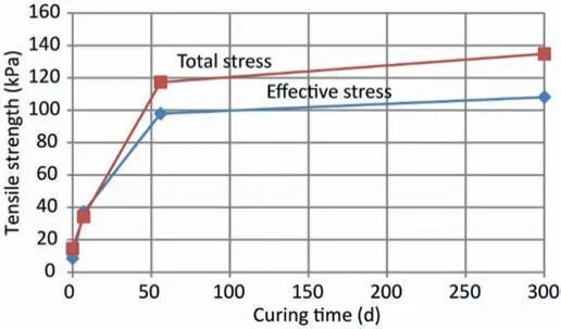
Fig.19.Evolution of total and effective tensile strength with curing time for CU triaxial tension tests.
5.Discussion
5.1.Three failure modes
After the results of triaxial compression and triaxial tension tests,it is proposed herein to adopt a more integrated approach by joining tensile and shear failures obtained in both compression and tensile tests.The failure experienced by the untreated specimen upon both tension and compression tests can occur under three failure modes: tensile failure,shear failure in compression,and shear failure in extension.Logically,triaxial compression tests induces shear failure in compression for all the confining pressure(from 86 kPa to 540 kPa).For the triaxial tension tests,confining pressures of 46 kPa and 103 kPa induces tensile failure while the higher confining pressures (186 kPa,298 kPa and 385 kPa)creates shear failure in tension.
Fig.20 shows the failure points together with the failure criteria in the deviator stress(q)vs.mean stress(p)plane in both effective and total stress references.In theq-pplane,the failure criteria are expressed as a function of the failure parameters (φc,φe,cc,ceandσt) as follow.
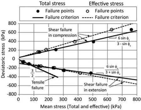
Fig.20.Shear and tensile failure criteria under effective and total stress references,obtained from triaxial compression and tension tests on untreated soils,plotted in the deviatoric stress (q) vs mean stress (p) plane.
For shear failure in compression,we have
For shear failure in extension,we have
For tensile failure,we have
whereφc,φe,cc,ceandσtare respectively the friction angle upon compressive shearing,the friction angle upon tensile shearing,the cohesion upon compressive shearing,the cohesion upon tensile shearing and the tensile strength.
For lime-treated specimen,the triaxial compression tests induce logically shear failure in compression for all the confining pressures while the triaxial tensile tests only produce failure under tensile mode,and no shear failure in extension is observed.This is due to the fact that the applied confining pressure is not high enough to generate shear failure in extension for the tensile failure mode before the shear failure in extension.
Fig.21 illustrates the failure criterion as a function of the confining pressure and the loading direction (tension or compression).Under triaxial tension loading,the transitional confining pressure,which separates the tensile failure mode and mode of shear failure in extension,depends essentially on the cohesion of the material.For low cohesion material (i.e.untreated soil in this case),the tensile failure criterion is of limited extent and is rapidly replaced by the criterion of shear failure in extension.At the opposite for high cohesion material (i.e.lime-treated soil in this case),tensile failure criterion occurs for a much larger range of confining pressure.So,the terms “low” and “high” confining pressures,as illustrated in Fig.21,must be considered as a function of transitional confining pressure,which is related to the cohesion of the material.
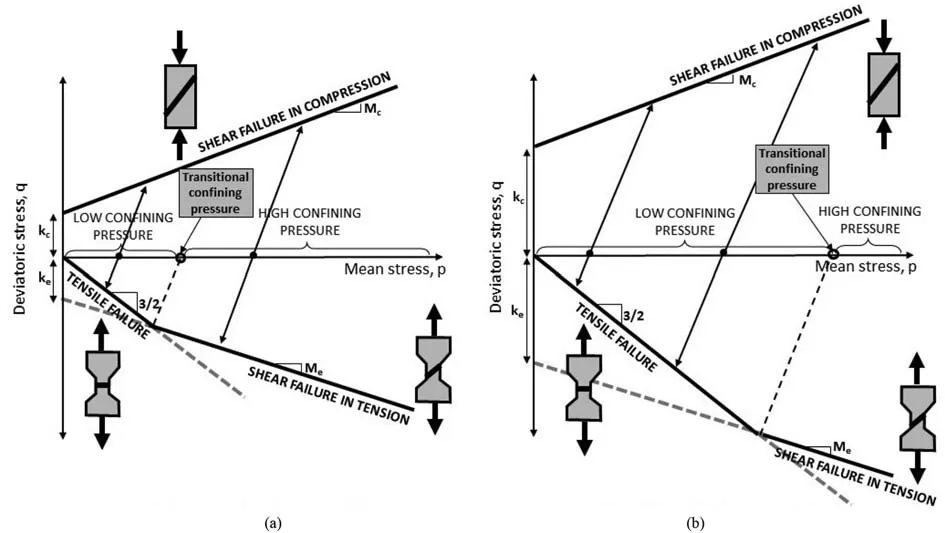
Fig.21.Three failure modes depend on the loading direction(tension or compression)and the magnitude of confining pressure with respect to the transitional confining pressure:(a) Low cohesion material (untreated soil),and (b) High cohesion material (treated soil).
Because of the different slopes of the shear failure criterion in compression(Mcin Eq.(12))and in extension(Mein Eq.(13),thepqplane does not allow to exhibit the possible mismatch in the shear failure parameters in compression and extension.Alternatively,the failure can be plotted in Mohr plane,using the concept of Mohr circle.Fig.22 shows the Mohr circles at failure and the deduced failure criteria in both effective and total stress references(Fig.22a and b,respectively).For the effective stress analysis,the failure points obtained from the CD direct shear test(Section 2.5)are also plotted.

Fig.22.Mohr circles and failure criteria plotted in the Mohr plane in (a) Effective normal stress and (b) Total normal stress.
Fig.22 reveals that the shear failure criteria are slightly different in compression and in extension,revealing a slight anisotropy of the material.This is induced by the mode of preparation of the specimen by dynamic compaction in the axial direction leading to a layered structure of the soil.The strength parameter obtained from the different tests are reported in Table 7.
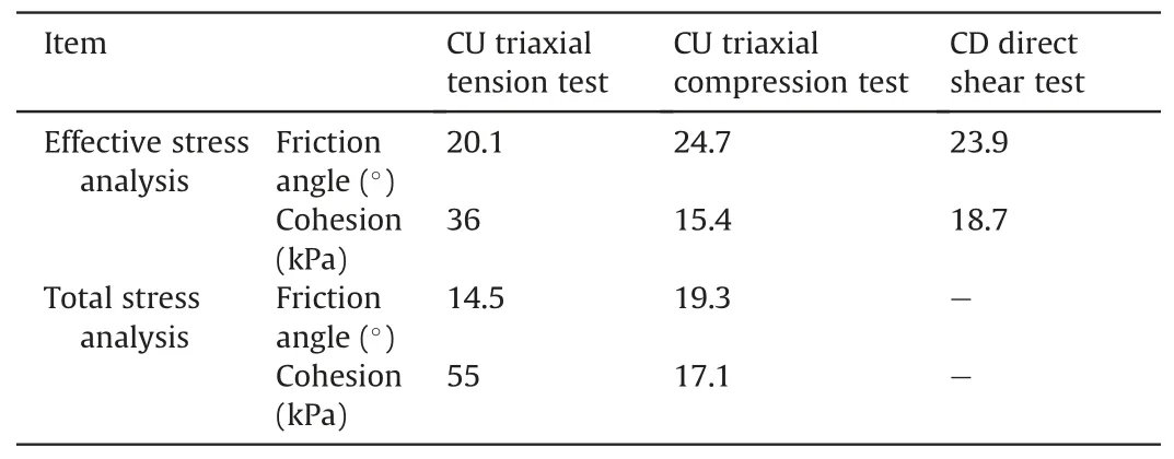
Table 7Shear failure parameters obtained from different tests.
5.2.Normalized stress-strain relationship
In order to compare the general trends of the stress-strain response of the materials experienced during the compression and tension triaxial tests under various confining pressures and various lime-treatment conditions,it is of interest to normalize the stress to compare all the results.Because the failure condition is defined as the maximum of the ratio between axial and radial effective stress (σ′a/σ′r),we chose this to compare all the curves together,as reported in Fig.23.
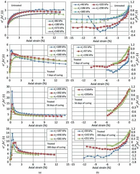
Fig.23.Normalized stress-strain curves as the effective axial stress -effective radial stress ratio as a function of axial strain for: (a) Triaxial compression tests and (b) Triaxial tension tests.
Upon triaxial compression,the untreated soil specimen develops a continuous hardening process,characteristics of normally(or slightly over-)consolidated state.It means that the compaction effort does not provide significant densification with respect to the different confining stresses applied.On the contrary,the soil treatment with lime,even at short curing time(i.e.7 d),can induce an over-consolidated state to the specimen with a peak-response followed by a softening process.This over-consolidated character increases with the curing time (at least until 56 d) and logically decreases with the confining pressure.It is to note that for the curing time of 56-300 d,the over-consolidation ratio seems to decreases slightly (the peak response is less pronounced at 300 d than at 56 d).This is consistent with the evolution of strength parameters (Fig.13 for cohesion and friction angle;Fig.19 for tensile strength)that tend to stabilize or even diminish between 56 d and 300 d.
Upon triaxial tension,untreated soil specimen experience hardening at high confining pressures and a more brittle response at low confining pressures,but still with an initial hardening before this brittle response.This is consistent with the fact that at high confining pressure,the failure occurs by shearing (leading to a possible hardening)while at low confining pressure,tensile failure takes place (leading to a more brittle failure).For lime-treated specimen,the normalized stress-strain curves exhibit a kind of mixed behavior.After a linear part corresponding to an elastic response,the curves deflect through hardening process,and finally reach a peak or a sudden interruption (before 15% axial deformation)corresponding to a brittle tensile failure.This mixed mode of behavior (hardening followed by a tensile failure) seems that the triaxial conditions,with application of a confining pressure,may lead to a shearing process that precedes the tensile failure.
6.Conclusions
The lime-treated clayey soils significantly increases its cohesion and its friction angle.Consequently,the soil may develop an important tensile strength that can play a role in the stability of geotechnical works.When investigating the geomechanical properties of lime-treated soils,it is important to quantify the tensile strength in a proper way,in addition to the more conventional compressive shear strength.
In this study,we combined triaxial compression and tension tests in order to deduce the shear and tensile strength parameters of an untreated and a lime-treated soil.Moreover,we adopted the triaxial tension test technique as originally developed by Bishop and Garga (1969).The CU conditions with a measure of pore water pressure allow us to analyze the failure state in terms of effective and total stress parameters.We deduced cohesions,friction angles and tensile strength for untreated and lime-treated soils(with 3% of lime) from 7 d to 300 days of curing.
Three failure modes were observed:tensile failure,shear failure in compression,shear failure in extension.For triaxial tension tests,the mode of failure depends on the magnitude of confining pressure with respect to the material cohesion.The failure can take place under shearing(at high confining pressure)or under tension(at low confining pressure).Consequently,those two failure modes require combining two failure criteria: a classical Mohr-Coulomb shear failure condition and a cut-off tensile strength condition that represents the tensile failure.
In geotechnical stability problem (like a slope),those three failure modes can coexist in a single mechanism.Tensile failure(characterized by open cracks) may take place at the crest of the slope;shear failure in extension occurs deeper in the slope;shear failure in compression develops at the toe of the slope.
In terms of shear failure,it is observed that the material exhibits a slight anisotropy because friction angles and cohesions obtained in compression shear and extensional shearing do not coincide exactly.This anisotropy is due to the compaction process that provides an oriented character of the soil.
When the material experiences tensile failure,the brittle rupture is preceded by the hardening process.This mixed mode of behavior seems that triaxial extension conditions lead to a shearing process before the occurrence of tensile failure.
Data availability statement
Some or all data,models,or code that support the findings of this study are available from the corresponding author upon reasonable request.
Declaration of competing interest
The authors declare that they have no known competing financial interests or personal relationships that could have appeared to influence the work reported in this paper.
 Journal of Rock Mechanics and Geotechnical Engineering2023年12期
- Journal of Rock Mechanics and Geotechnical Engineering的其它文章
- The formation of orthogonal joint systems and cuboidal blocks: New insights gained from flat-lying limestone beds in the region of Havre-Saint-Pierre (Quebec,Canada)
- Numerical analysis of the effects of vesicle distribution characteristics on the engineering properties of volcanic rocks
- A hybrid attention deep learning network for refined segmentation of cracks from shield tunnel lining images
- 3D limit analysis of rock slopes based on equivalent linear failure criterion with tension cut-off
- Mutual impact of true triaxial stress,borehole orientation and bedding inclination on laboratory hydraulic fracturing of Lushan shale
- Unloading-induced permeability recovery in rock fractures
