
Core-drilling kinematic modeling and analysis of Jiaolong submersible manipulator
2023-11-18 08:39XuYANGXinLIUShizhenLIYugangRENLiminZHU
Xu YANG, Xin LIU, Shizhen LI, Yugang REN, Limin ZHU
Research Article
Core-drilling kinematic modeling and analysis of Jiaolong submersible manipulator

1Institute of Marine Science and Technology, Shandong University, Qingdao 266237, China2National Deep Sea Center, Qingdao 266237, China3State Key Laboratory of Mechanical System and Vibration, Shanghai Jiao Tong University, Shanghai 200240, China
The complicated topographies of the deep sea pose significant challenges for the core drilling with the Jiaolong submersible manipulator. To address this problem, we proposed a core-drilling kinematic model and evaluated the core-drilling behavior of the submersible manipulator by comprehensively considering the uncertain posture of the Jiaolong submersible. First, we established a forward kinematic model for the core-drilling task in deep sea, which satisfied the requirement of gravitational-direction core drilling. Based on the forward kinematic equations, we then built a double-redundancy inverse kinematic model, which was able to determine the required motion trajectories of six active joints according to the desired core-drilling trajectory. The core-drilling workspaces and the motions of the Jiaolong submersible manipulator were assessed with several calculation examples. The established forward and inverse kinematic models are constructed with clear analytic equations, and thus are directly applicable to the Jiaolong submersible manipulator-based core-drilling task.
Kinematic model; Core drilling; Jiaolong submersible manipulator; Uncertain posture
1 Introduction
The deep sea is the last vast area on earth that has not been extensively explored and developed, and is rich in minerals, energy, medicinal substances, various forms of life, and many other natural resources (Lauro et al., 2009). Submersibles are key apparatuses for exploring, developing, and protecting the deep sea (Zhang et al., 2017). By 2018, 160 submersibles were in service around the world (Kohnen, 2018), some of which had even reached the Challenger Deep of the Mariana Trench, the Galapas Rift of the Eastern Pacific Ocean, and the Mid-Atlantic Ridge (Kohnen, 2013).
Core drilling along the gravitational direction is one important task for submersibles; it plays an important role in detecting polymetallic sulfides (Iizasa et al., 1999), gas hydrate (Khlystov et al., 2013), ferromanganese crust (Chu et al., 2005), sediment (Reagan et al., 2017), and many other resources in the deep sea. In 1991, the American ALVIN submersible successfully performed core-drilling operations at 2100-m water depth and obtained samples representing the progressive mineral growth of chimneys (Stakes et al., 1992). During the cruise of the French Nautile submersible in 1996, 66 basaltic rock samples were collected from the center of the Mid-Atlantic Ridge (Ravilly et al., 2001). The Chinese Jiaolong submersible obtained mud volcano samples from the Mariana Trench (Ren et al., 2021) and cobalt-rich crust samples from the Vega Seamount (Yao et al., 2021). The Japanese Shinkai 6500 submersible collected microplastic sediment samples from the deep-sea floor in Japanese waters (Tsuchiya et al., 2019). To accommodate the complicated topographies of the deep sea, submersibles usually operate a core-drilling rig with a multi-degree-of-freedom manipulator (Wu et al., 2014). Nevertheless, it is a challenging task to determine the right position and posture trajectories for deep-sea manipulators in order to accomplish a core-drilling operation.
To solve the trajectory issues of deep-sea manipulators, much research work on kinematic modeling has been carried out. For example, Khan and Quan (2015) established a forward kinematic model for the Puma 560 underwater manipulator. Chen et al. (2021) obtained the inverse kinematic model of a 6-degree-of-freedom (DOF) underwater manipulator by using the Jacobi matrix generalized inverse method. Qiao et al. (2010) resolved the inverse kinematic equations for a general 6R serial manipulator by double quaternions. Zhang et al. (2022) proposed to solve the inverse kinematic of a deep-sea hydraulic manipulator by combining the geometric method and the Euler angles solution. Finally, Luo et al. (2022) employed a multi-objective full-parameter optimization particle swarm optimization algorithm to improve the accuracy, efficiency, and stability of inverse kinematic calculation. However, the existing research is focused on kinematic models of underwater manipulators. Manipulator-based core drilling is different and complex which involves six active joints and one passive joint. In addition, the core-drilling trajectory must be along the gravitational direction regardless of the posture of the submersible.
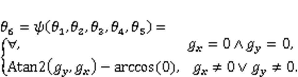
Motivated by the urgent needs of deep-sea core drilling, we established a functionalized kinematic model for the Jiaolong submersible manipulator in this study. We took the submersible posture and the gravitational constraint into account to build a forward kinematic model for the Jiaolong submersible manipulator-based core-drilling task. The established forward kinematic model can ensure a specific sediment-direction drilling posture by solving the angular displacement of joint 6 based on the angular displacements of joints 1–5 and the submersible posture. Furthermore, we deduced a double-redundancy inverse kinematic algorithm by means of the iterative elimination method. The trajectories in joint space can be analytically determined with the established inverse kinematic model.
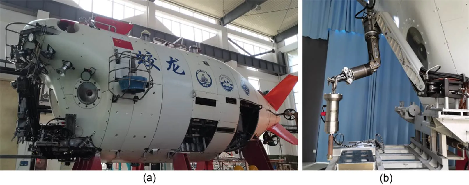
Fig. 1 Jiaolong manned submersible (a) and manipulator-based core drilling (b)
The main contribution of this research lies in solving the forward and inverse problems of the Jiaolong submersible manipulator-based core-drilling task. The rest of the paper is organized as follows. The core-drilling operation of the Jiaolong submersible manipulator is introduced in Section 2. The core-drilling forward kinematic model is built in Section 3. A double-redundancy inverse kinematic model is presented in Section 4. Section 5 covers the Jiaolong submersible manipulator-based core-drilling operation simulations and analysis. Finally, conclusions are drawn in Section 6.
2 Jiaolong submersible manipulator-based core drilling
The Jiaolong submersible is the first Chinese deep-sea manned submersible and offers several unique features: a maximum operational depth of 7062 m (Cui, 2013), dimensions of 8.4 m×3.9 m×3.4 m (Zhang et al., 2016), a weight of 22 t (Liu et al., 2010), a crew of one pilot and two scientists (Zhu, 2020), and a manned cabin with an inner diameter of 2.1 m (Wang et al., 2020), as shown in Fig. 1a. The Jiaolong submersible is capable of working across 99.8% of the world's ocean area (Zhang et al., 2018). It is equipped with two seven-function manipulators that can accomplish various deep-sea tasks such as geological sampling, biological sampling, seawater sampling, and in-situ cutting (Sivčev et al., 2018). While performing core drilling of deposit sediment in the deep sea, the Jiaolong submersible manipulator is required to actuate the core-drilling rig along the gravitational direction, as shown in Fig. 1b.
The Jiaolong submersible manipulator is a six-DOF serial robot with additional grasping function (Orion 7PE, Schilling Robotics, LLC, USA), as shown in Fig. 2a. Active joints 1, 2, 3, and 5 are revolute pairs driven by hydraulic cylinders. Active joints 4 and 6 are revolute pairs driven by hydraulic motors. The end-jaw is actuated by a hydraulic cylinder. In order to facilitate rapid grabbing and a constant mechanical relationship, the core-drilling rig is usually connected with the end-jaw through a passive revolute pair. As a result, passive joint 7 is a revolute pair without actuation. By controlling the angular positions of six active joints, the Jiaolong submersible manipulator can adjust the position and posture of the core-drilling rig. The key parameters of Jiaolong submersible manipulator are: 7000-m rated water depth, weight in air of 61 kg, weight in seawater of 43 kg, and 55.3-kg lift at full extension. Despite of the uncertain submersible posture, the position and posture of the core-drilling rig can be maintained by regulating the manipulator trajectory.
3 Core-drilling forward kinematic model
3.1 Posture modeling of the Jiaolong submersible
First, we established a world coordinate (w-coordinate) and a base coordinate (0-coordinate), as shown in Fig. 2b. The origins of the w-coordinate and the 0-coordinate are attached to each other. Thewaxis of the w-coordinate is arranged along the gravitational direction. The0axis of the 0-coordinate is along the shaft axis of joint 1. The0axis of the 0-coordinate is along the common normal line of the shaft axes of joints 1 and 2 (while the angle of joint 1 is zero). The0axis of the 0-coordinate is determined with the right-hand rule. The roll-pitch-yaw (RPY) angles (Li et al., 2007; Wang et al., 2018) are used to describe the position and posture relationship between the w-coordinate and the 0-coordinate. The transformation matrix which denotes the effect of an uncertain submersible posture on the manipulator can be expressed by:
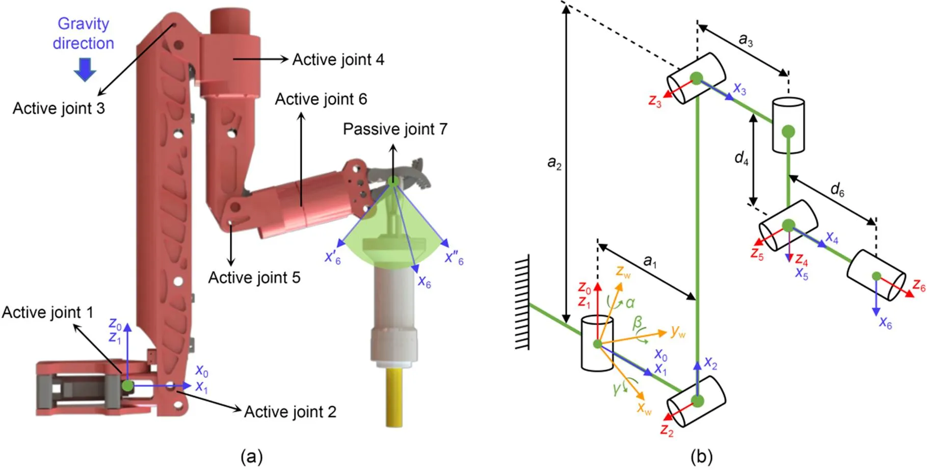
Fig. 2 Jiaolong submersible manipulator-based core drilling (a) and coordinates of Jiaolong submersible manipulator (b)

3.2 Jiaolong manipulator kinematic modeling
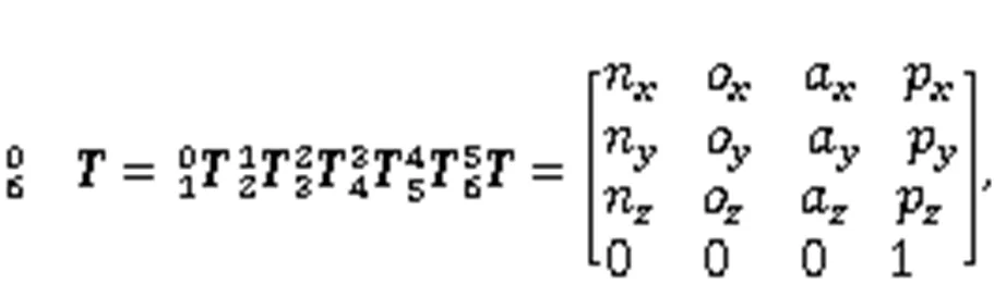
Six linkage coordinate systems {} (-coordinate,=1, 2, …, 6) were established for the Jiaolong submersible manipulator, using the Denavit-Hartenberg method (Roh and Kim, 2004; Dereli and Köker, 2020; Xiao et al., 2021, Li et al., 2022), as shown in Fig. 2b. The origins of the 1-coordinate and the 0-coordinate were attached to each other. The1axis of the 1-coordinate was along the0axis of the 0-coordinate. The1axis of the 1-coordinate was along the common normal line of the shaft axes of joints 1 and 2. The origin of the 2-coordinate was attached to joint 2. The2axis of the 2-coordinate was along the shaft axis of joint 2. The2axis of the 2-coordinate was along the common normal line of the shaft axes of joints 2 and 3. The origin of the 3-coordinate was attached to joint 3 and the3axis of the 3-coordinate was along the shaft axis of joint 3. The3axis of the 3-coordinate was along the common normal line of the shaft axes of joints 3 and 4. The origin of the 4-coordinate was attached to joint 4. The4axis of the 4-coordinate was along the shaft axis of joint 4. The4axis of the 4-coordinate was along the cross-product direction of5and4. The origin of the 5-coordinate was attached to joint 5. The5axis of the 5-coordinate was along the shaft axis of joint 5. The5axis of the 5-coordinate was along the cross-product direction of6and5. The origin of the 6-coordinate was attached to the manipulator's end-jaw. The6axis of the 6-coordinate was along the shaft axis of joint 6. The6axis of the 6-coordinate was parallel to the5axis of the 5-coordinate. To describe the geometrical relationship between various linkages, we defined link parametersa-1,α-1,d, andθ(=1, 2, …, 6).a-1is the length of link-1,α-1is the angle fromz-1tozaroundx-1axis,dis the distance fromx-1toxalongzaxis, andθis the angle fromx-1toxaroundzaxis. The kinematic transformation matrix from the 0-coordinate to the 6-coordinate of the Jiaolong manipulator is:
3.3 Core-drilling forward kinematic modeling
Taking the posture of the Jiaolong submersible into account, the transformation matrix from the w-coordinate to the 6-coordinate is:


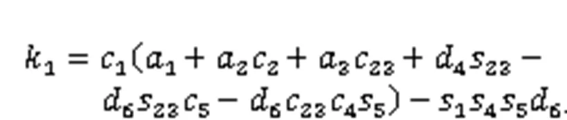
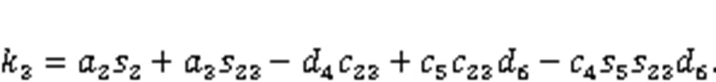
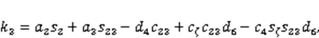
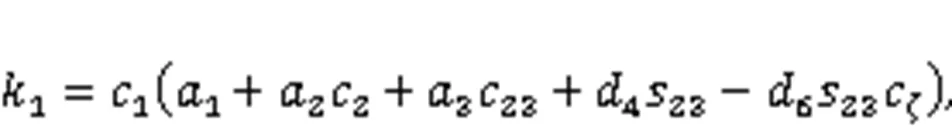
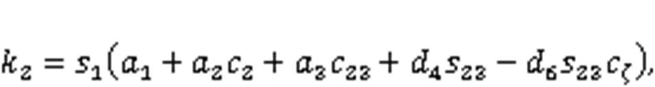
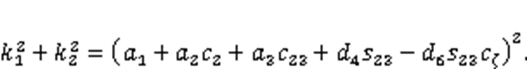
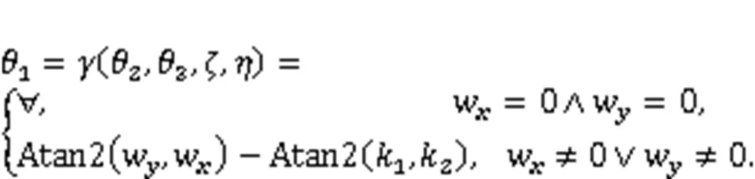
wheresdenotes sinθ(=1, 2, …, 6),cdenotes cosθ(=1, 2, …, 6),θ(=1, 2, …, 6) denotes the joint variable of theth joint,sdenotes sin(θ+θ), andcdenotes cos(θ+θ).
By using trigonometrical substitution, Eq. (5) can be rewritten as:


4 Core-drilling inverse kinematic model
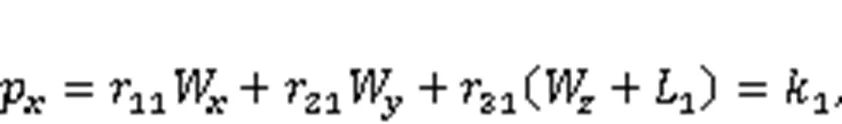
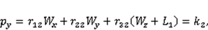
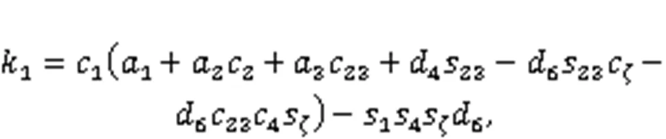
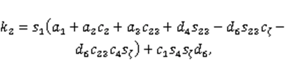
Based on the established core-drilling forward kinematic model of the Jiaolong submersible manipulator, we built a double-redundancy inverse kinematic model in this section. Given the core-drilling position (the tip position of the core-drilling rig in the w-coordinate) [WWW]Tand the length of core-drilling rig1, the following formulas can be obtained:
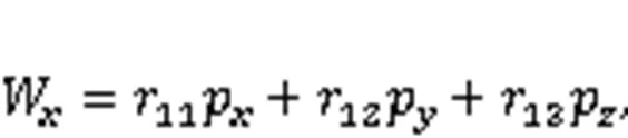
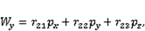
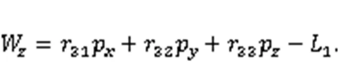
From Eqs. (11)–(13), the position of the manipulator's end-jaw can be obtained as:

Substituting Eqs. (14)–(16) into Eq. (10), the following three position-constraint equations can be obtained:

Considering that five joint variables (1,2,3,4, and5) are unknown, the joint variables2and3are set as the independent variables.
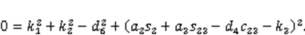
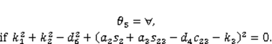
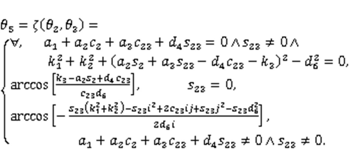
4.1 Solution of joint variable θ5
By combining Eqs. (17) and (18), a new position-constraint equation can be derived:

Substituting Eqs. (22) and (23) into Eq. (21), Eq. (21) can be rewritten as:

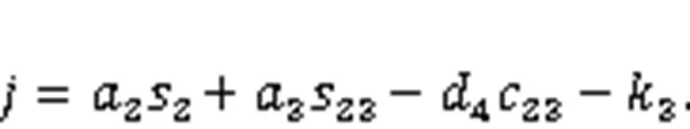
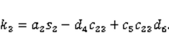


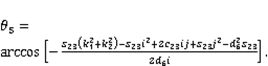
By substituting=0 into Eq. (24), Eq. (24) can be rewritten as:
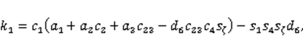
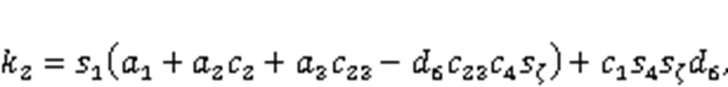
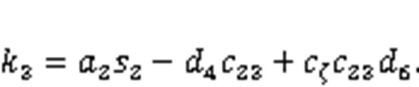
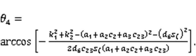
4.2 Solution of joint variable θ4
Substituting Eq. (32) into Eqs. (17)–(19), the three position-constraint equations can be rewritten as:

Combining Eqs. (36) and (37), the following formula can be obtained:
Eqs. (38) and (39) are not influenced by joint variable4. The analytical solution of4in case 1 can be obtained as:

Combining Eqs. (41) and (42), the following formula can be obtained:

The analytical solution of4in case 2 can be obtained from Eq. (44) as follows:
Combining Eqs. (46) and (47), the following formula can be obtained:
According to Eq. (49), joint variable4has no effect on Eq. (49). The analytical solution of4in case 3 can be obtained as:
From Eq. (35), the analytical solution of4in case 4 can be obtained as:

In summary, the analytical solution of4can be expressed as:

4.3 Solution of joint variable θ1
Substituting the results obtained from Eqs. (32) and (52) into Eqs. (17) and (18), Eqs. (17) and (18) can be rewritten as:


Eqs. (53) and (54) can be rewritten as:
From Eqs. (57) and (58), the analytical solution of1in case 1 can be obtained as:

According to Eqs. (60) and (61), joint variable1has no effect on the-position or-position of the manipulator's end-jaw. The analytical solution of1in case 2 can be obtained as:
In summary, the analytical solution of1can be expressed as:
4.4 Model verification
Table S1 in the electronic supplementary materials (ESM) depicts the key points of desired core-drilling trajectory A, the calculated joint trajectory, and the resulted core-drilling-tip trajectory. The calculated joint trajectory is determined based on the desired core-drilling trajectory A by means of the established double-redundancy inverse kinematic model. The resulted core-drilling-tip trajectory is resolved according to the calculated joint trajectory (the calculated1–6in Table S1) by means of the established core-drilling forward kinematic model presented in Section 3. As can be seen from Table S1, high consistency between desired core-drilling trajectory A and the resulted core-drilling-tip trajectory is observed. Trajectory A can also be fulfilled by other joint trajectories (1,4,5, and6) if2and3are preset to be different values. Hence, the established double-redundancy inverse kinematic model is effective for solving the trajectories of six active joints according to desired core-drilling trajectory.
5 Case study
The core-drilling workspaces and the core-drilling trajectories of Jiaolong submersible manipulator are simulated and analyzed in this section. The mechanical parameters of the manipulator are depicted in Table 1. The length of the core-drilling rig1was set as 620 mm.
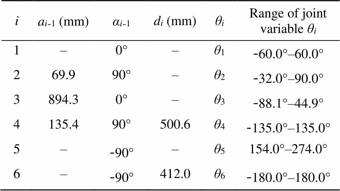
Table 1 Parameters of the Jiaolong submersible manipulator
5.1 Core-drilling workspace analysis
Using the established core-drilling forward kinematic model, we simulated the core-drilling workspace of the Jiaolong submersible without incline and rotation (yaw angle=0°, pitch angle=0°, and roll angle=0°), as shown in Fig. 3. While calculating the core-drilling points within the workspace, each joint variable was defined by 20 points evenly spaced throughout the range (resulting in 3.2×10⁶discrete working points across the workspace). The 3D view of the core-drilling workspace of the Jiaolong submersible manipulator in the w-coordinate is depicted in Fig. 3a. The-,-, and-views of the core-drilling workspace in the w-coordinate are shown in Figs. 3b–3d, respectively. The core-drilling workspace surrounds the manipulator, the envelope surface of which is like an ellipsoid. The reachable core-drilling motion range was: -300.5–1847.0 mm in thedirection, -1656.6–1656.6 mm in thedirection, and -2023.7–1133.9 mm in thedirection.

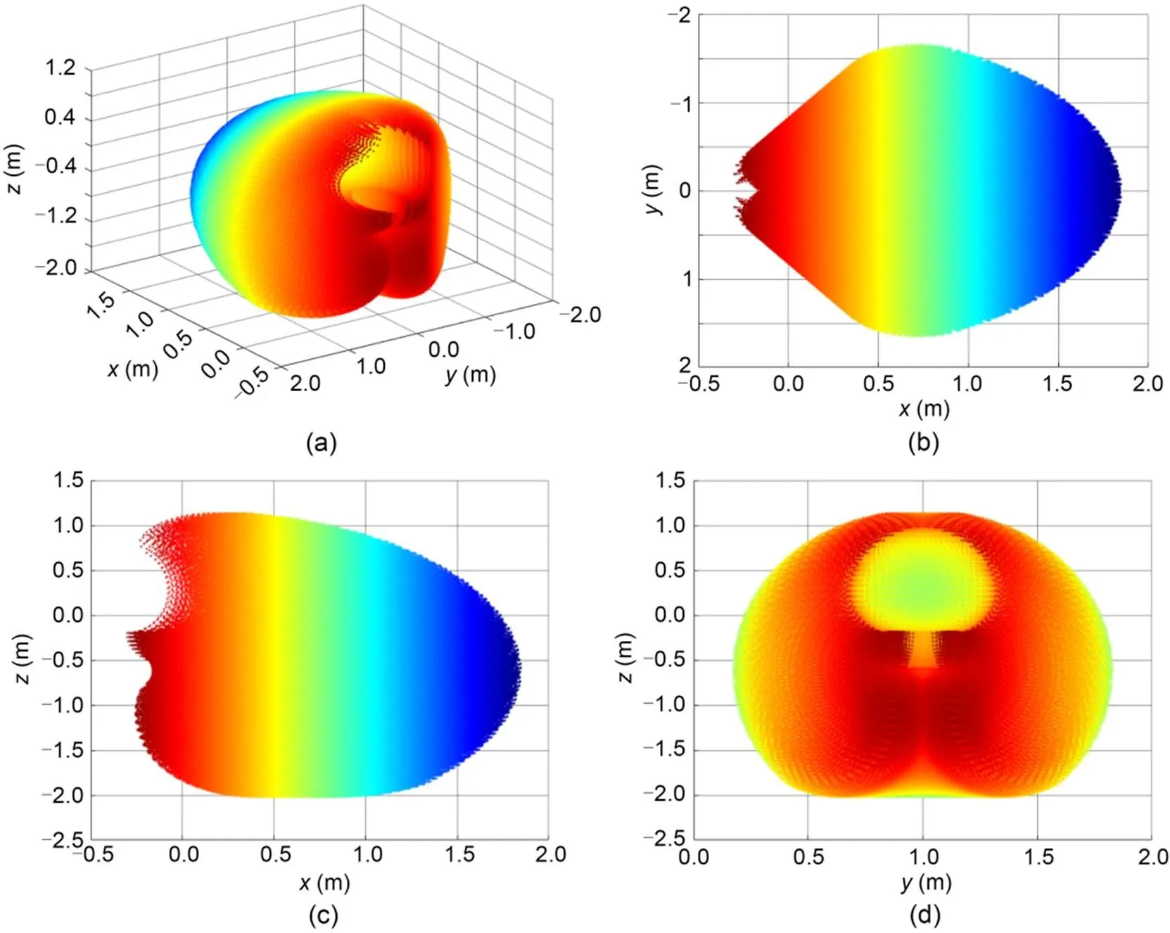
Fig. 3 Core-drilling workspace of the Jiaolong submersible manipulator without incline and rotation (α=0°, β=0°, and γ=0°): (a) 3D view; (b) x-y view; (c) x-z view; (d) y-z view
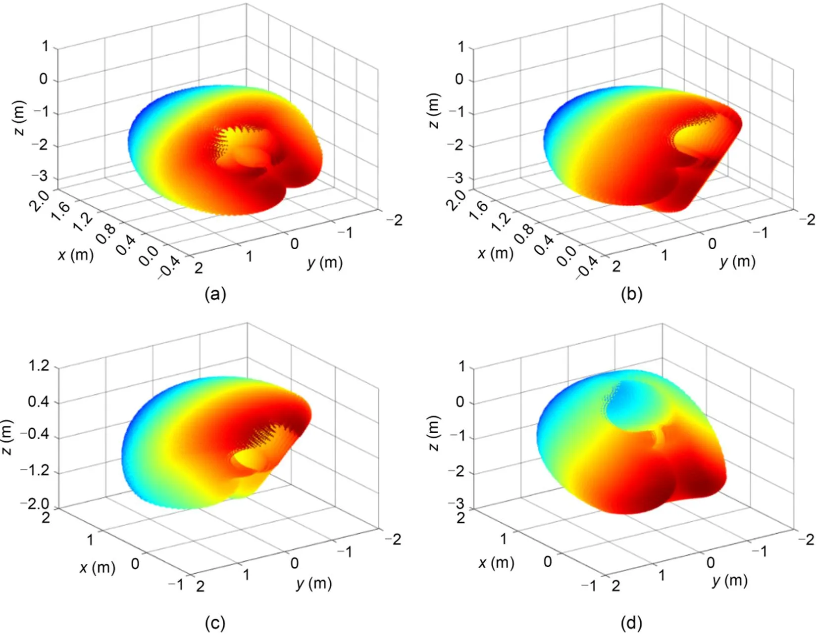
Fig. 4 Core-drilling workspace of the Jiaolong submersible manipulator with different postures: (a) α=0°, β=0°, and γ=-30°; (b) α=0°, β=0°, and γ=30°; (c) α=0°, β=-30°, and γ=0°; (d) α=0°, β=30°, and γ=0°
5.2 Core-drilling trajectory analysis
Based on the double-redundancy inverse kinematic model of the Jiaolong submersible manipulator, we simulated and analyzed the core-drilling joint trajectories. As shown in Fig. 5, we designed a core-drilling trajectory A (start point: (1000, 0, -900) mm; end point: (1000, 0, -1200) mm). Trajectory A could be executed by forcing the six active rotational joints of the manipulator to move along the designed joint trajectory. When2and3were preset (according to the established core-drilling inverse kinematic model in Section 4, joint variables2and3are independent variables which should be set before inverse kinematic calculation), the four joint trajectories (1,4,5, and6) of Jiaolong submersible manipulator could be determined. Fig. 6 depicts the required joint trajectories for core-drilling trajectory A when the Jiaolong submersible was in a horizontal posture with=0°,=0°, and=0° and in an incline posture with=0°,=10°, and=10°.
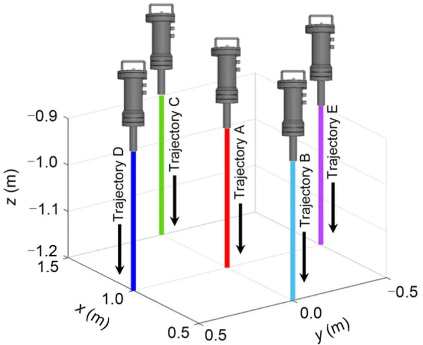
Fig. 5 Core-drilling trajectories A, B, C, D, and E
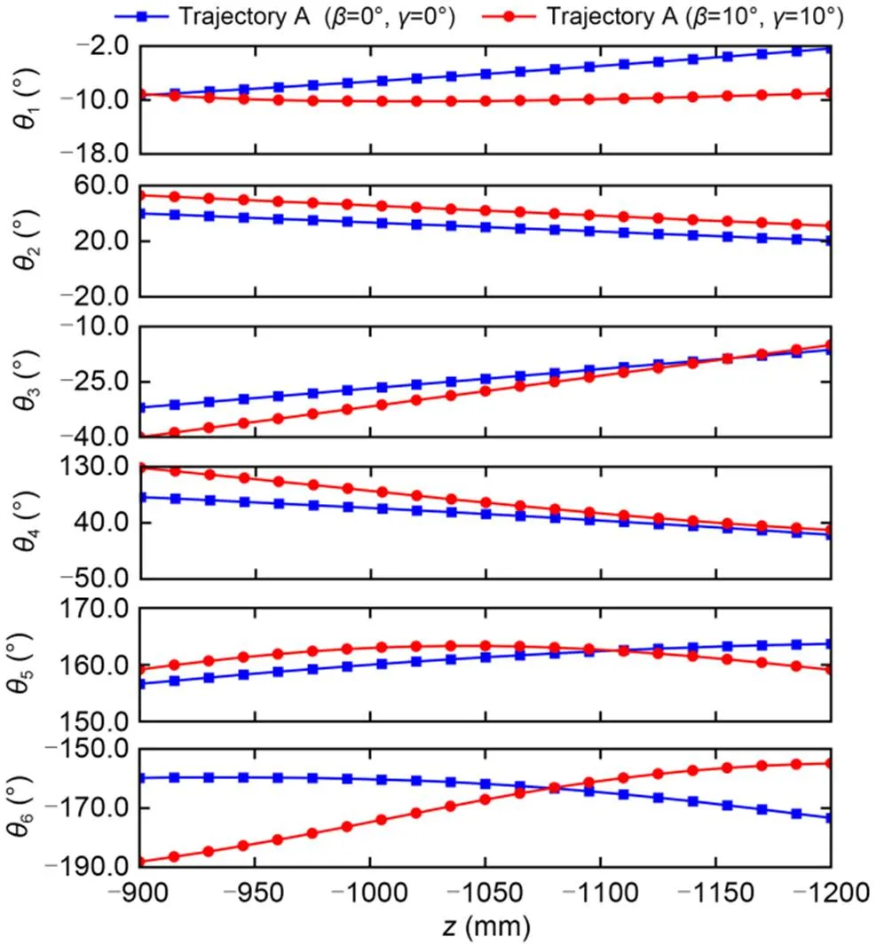
Fig. 6 Six joint variables (θ1, θ2, θ3, θ4, θ5, and θ6) of core-drilling trajectory A with Jiaolong submersible manipulator in two different postures
In addition, we designed another four core-drilling trajectories: trajectory B (start point: (500, 0, -900) mm; end point: (500, 0, -1200) mm), trajectory C (start point: (1500, 0, -900) mm; end point: (1500, 0, -1200) mm), trajectory D (start point: (1000, 500, -900) mm; end point: (1000, 500, -1200) mm), and trajectory E (start point: (1000, -500, -900) mm; end point: (1000, -500, -1200) mm), as shown in Fig. 5. We solved the six joint trajectories of the manipulator for the four core-drilling trajectories, as depicted in Fig 7. Therefore, the double-redundancy inverse kinematic model is computationally effective.
6 Conclusions
This paper proposed a core-drilling kinematic model for the Jiaolong submersible manipulator, comprised of two key parts: forward kinematics and inverse kinematics. Based on the established kinematic model, several numerical examples corresponding to the core-drilling tasks under different submersible postures were carried out. Three main conclusions can be drawn:
(1) The core-drilling posture (along the gravitational direction) of the Jiaolong submersible manipulator can be guaranteed by regulating the sixth active joint according to the other five active joints of the manipulator and the posture of the Jiaolong submersible. Herein, the core-drilling forward kinematics of Jiaolong submersible manipulator involves five independent variables.
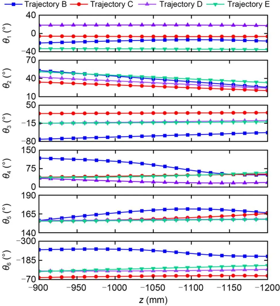
Fig. 7 Six joint variables (θ1, θ2, θ3, θ4, θ5, and θ6) of core-drilling trajectories B, C, D, and E with Jiaolong submersible manipulator at α=0°, β=10°, and γ=10°
(2) The core-drilling trajectory can be realized by enforcing the first, fourth, and fifth active joints along the solved trajectories while the second and third active joints are in preset positions. Meanwhile, the sixth active joint should be regulated to assure a constant core-drilling posture.
(3) The Jiaolong submersible manipulator is able to perform core-drilling task in an ellipsoid workspace with an-directional range of -300.5–1847.0 mm, a-directional range of -1656.6–1656.6 mm, and a-directional range of -2023.7–1133.9 mm (in the w-coordinate) while the submersible is without incline and rotation.
Acknowledgments
This work is supported by the National Natural Science Foundation of China (No. 52175018) and the Key R&D Program of Shandong Province (Major Scientific and Technological Innovation Project) (No. 2019JZZY010802), China.
Author contributions
Xu YANG and Xin LIU designed the research and processed the corresponding data. Yugang REN, Shizhen LI, and Limin ZHU wrote the first draft of the manuscript. Xu YANG and Xin LIU organized the manuscript. Xu YANG, Shizhen LI, and Yugang REN revised and edited the final version.
Conflict of interest
Xu YANG, Xin LIU, Shizhen LI, Yugang REN, and Limin ZHU declare that they have no conflict of interest.
Chen P, Long JC, Yang W, et al., 2021. Inverse kinematics solution of underwater manipulator based on Jacobi matrix. OCEANS 2021: San Diego–Porto, p.1-4. https://doi.org/10.23919/OCEANS44145.2021.9705690
Chu FY, Qian XY, Zhang HS, et al., 2005. Discovery of ferromanganese crust boundary and its genetic and ore prospecting significance., 6(7):656-662. https://doi.org/10.1631/jzus.2005.A0656
Cui WC, 2013. Development of the Jiaolong deep manned submersible., 47(3):37-54. https://doi.org/10.4031/MTSJ.47.3.2
Dereli S, Köker R, 2020. A meta-heuristic proposal for inverse kinematics solution of 7-DOF serial robotic manipulator: quantum behaved particle swarm algorithm., 53(2):949-964. https://doi.org/10.1007/s10462-019-09683-x
Iizasa K, Fiske RS, Ishizuka O, et al., 1999. A Kuroko-type polymetallic sulfide deposit in a submarine silicic caldera., 283(5404):975-977. https://doi.org/10.1126/science.283.5404.975
Khan A, Quan WL, 2015. Forward kinematic modeling and analysis of 6-DOF underwater manipulator. International Conference on Fluid Power and Mechatronics, p.1093-1096. https://doi.org/10.1109/FPM.2015.7337281
Khlystov O, de Batist M, Shoji H, et al., 2013. Gas hydrate of Lake Baikal: discovery and varieties., 62:162-166. https://doi.org/10.1016/j.jseaes.2012.03.009
Kohnen W, 2013. Review of deep ocean manned submersible activity in 2013., 47(5):56-68. https://doi.org/10.4031/MTSJ.47.5.6
Kohnen W, 2018. MTS manned underwater vehicles 2017-2018 global industry overview., 52(5):125-151. https://doi.org/10.4031/MTSJ.52.5.9
Lauro FM, McDougald D, Thomas T, et al., 2009. The genomic basis of trophic strategy in marine bacteria., 106(37):15527-15533. https://doi.org/10.1073/pnas.0903507106
Li GF, Xiao F, Zhang XF, et al., 2022. An inverse kinematics method for robots after geometric parameters compensation., 174:104903. https://doi.org/10.1016/j.mechmachtheory.2022.104903
Li LY, Li X, Zhou X, et al., 2007. Study of off-line programming system of arc robot based on the software of ROBOGUIDE.: Tarn TJ, Chen SB, Zhou CJ (Eds.), Robotic Welding, Intelligence and Automation. Springer, Berlin, Germany, p.401-408. https://doi.org/10.1007/978-3-540-73374-4_48
Liu F, Cui WC, Li XY, 2010. China’s first deep manned submersible, JIAOLONG., 53(10):1407-1410. https://doi.org/10.1007/s11430-010-4100-2
Luo S, Chu DM, Li QD, et al., 2022. Inverse kinematics solution of 6-DOF manipulator based on multi-objective full-parameter optimization PSO algorithm., 16:791796. https://doi.org/10.3389/fnbot.2022.791796
Qiao SG, Liao QZ, Wei SM, et al., 2010. Inverse kinematic analysis of the general 6R serial manipulators based on double quaternions., 45(2):193-199. https://doi.org/10.1016/j.mechmachtheory.2009.05.013
Ravilly M, Horen H, Perrin M, et al., 2001. NRM intensity of altered oceanic basalts across the MAR (21°N, 0‒1.5 Ma): a record of geomagnetic palaeointensity variations?, 145(2):401-422. https://doi.org/10.1046/j.1365-246x.2001.01381.x
Reagan MK, Pearce JA, Petronotis K, et al., 2017. Subduction initiation and ophiolite crust: new insights from IODP drilling., 59(11):1439-1450. https://doi.org/10.1080/00206814.2016.1276482
Ren YG, Yang L, Liu YJ, et al., 2021. Experimental research on the process parameters of a novel low-load drill bit used for 7000 m bedrock sampling base on manned submersible., 9(6):682. https://doi.org/10.3390/jmse9060682
Roh HS, Kim JO, 2004. Manipulator modeling from D-H parameters. The 30th Annual Conference of IEEE Industrial Electronics Society, p.2480-2485. https://doi.org/10.1109/IECON.2004.1432190
Sivčev S, Coleman J, Omerdić E, et al., 2018. Underwater manipulators: a review., 163:431-450. https://doi.org/10.1016/j.oceaneng.2018.06.018
Stakes D, Moore WS, Tengdin T, et al., 1992. Cores drilled into active smokers on Juan de Fuca Ridge., 73(26):273-283. https://doi.org/10.1029/91EO00220
Tsuchiya M, Nomaki H, Kitahashi T, et al., 2019. Sediment sampling with a core sampler equipped with aluminum tubes and an onboard processing protocol to avoid plastic contamination., 6:2662-2668. https://doi.org/10.1016/j.mex.2019.10.027
Wang D, Wu J, Wang LP, 2018. Research on the error transfer characteristics of a 3-DOF parallel tool head., 50:266-275. https://doi.org/10.1016/j.rcim.2017.10.002
Wang WZ, Zhang SS, Ye C, et al., 2020. A new method for optimizing the cabin layout of manned submersibles., 2020:6626602. https://doi.org/10.1155/2020/6626602
Wu SJ, Yang CJ, Huang HC, et al., 2014. Development of an electric control gas-tight sampler for seafloor hydrothermal fluids., 15(2):120-129. https://doi.org/10.1631/jzus.A1300233
Xiao F, Li GF, Jiang D, et al., 2021. An effective and unified method to derive the inverse kinematics formulas of general six-DOF manipulator with simple geometry., 159:104265. https://doi.org/10.1016/j.mechmachtheory.2021.104265
Yao HQ, Liu YG, Yang Y, et al., 2021. Assessment of acoustic backscatter intensity surveying on deep-sea ferromanganese crust: constraints from Weijia Guyot, western Pacific Ocean., 4(2):288-298. https://doi.org/10.31035/cg2020046
Zhang J, Li W, Yu JC, et al., 2017. Study of manipulator operations maneuvered by a ROV in virtual environments., 142:292-302. https://doi.org/10.1016/j.oceaneng.2017.07.008
Zhang TW, Ding ZJ, Zhao SY, et al., 2016. Positioning sonars of Jiaolong human occupied vehicle: basic principle and sea trial. OCEANS 2016–Shanghai, p.1-4. https://doi.org/10.1109/OCEANSAP.2016.7485336
Zhang TW, Tang JL, Li ZG, et al., 2018. Use of the Jiaolong manned submersible for accurate mapping of deep-sea topography and geomorphology., 61(8):1148-1156. https://doi.org/10.1007/s11430-017-9187-3
Zhang Y, Li XH, Yu TT, et al., 2022. Trajectory planning of deep-sea hydraulic manipulator in joint space with flow constraints. International Symposium on Control Engineering and Robotics, p.31-37. https://doi.org/10.1109/ISCER55570.2022.00012
Zhu M, 2020. Acoustic system of Jiaolong manned submersible and its future development.: Chinese Academy of Sciences, Cyberspace Administration of China, Ministry of Education of the PRC, et al. (Eds.), China’s e-Science Blue Book 2018. Springer, Singapore, p.171-186. https://doi.org/10.1007/978-981-13-9390-7_9
Electronic supplementary materials
Table S1
题目:蛟龙号载人深潜器机械臂岩芯取样运动学建模与分析
作者:杨旭1,刘鑫1,李世振1,任玉刚2,朱利民3
机构:1山东大学,海洋研究院,中国青岛,266237;2国家深海基地管理中心,中国青岛,266237;3上海交通大学,机械系统与振动国家重点实验室,中国上海,200240
目的:在具有不确定地形特点的深海环境下,基于蛟龙号载人深潜器机械臂开展重力沉积方向的岩芯取样作业是深海技术领域的一个重要挑战。本文旨在探讨蛟龙号载人深潜器机械臂岩芯取样的运动学特点,并提出实现蛟龙号载人深潜器机械臂岩芯取样作业的关节轨迹调控方法。
创新点:1. 揭示蛟龙号载人深潜器可实现的岩芯取样作业空间;2. 提出一种可完成重力沉积方向岩芯取样任务的机械臂关节轨迹设置方法。
方法:1. 建立蛟龙号载人深潜器机械臂与深海地理环境间的姿态转换模型;2. 建立机械臂操纵钻机实现重力方向岩芯取样的运动学正解与逆解模型;3. 通过对机械臂第六主动关节的调节,实现岩芯钻机姿态的稳定保持;4. 通过计算分析,揭示蛟龙号载人深潜器在不同坐地姿态下可实现的岩芯取样空间,并计算典型岩芯取样任务所需的机械臂关节轨迹。
结论:1. 可以通过调节蛟龙号载人深潜器机械臂第六个主动关节,实现岩芯钻机作业姿态的稳定保持;2. 基于蛟龙号载人深潜器机械臂的岩芯取样作业,可通过预设第二和第三主动关节轨迹并同时主动调节第一、第四、第五和第六主动关节轨迹来实现;3. 蛟龙号载人深潜器水平坐地时,其岩芯取样作业空间类似椭球体:方向的范围为−300.5~1847.0 mm,方向的范围为−1656.6~1656.6 mm,方向的范围为−2023.7~1133.9 mm。
关键词:蛟龙号载人深潜器;不确定姿态;岩芯取样;运动学模型
https://doi.org/10.1631/jzus.A2200484
https://doi.org/10.1631/jzus.A2200484
Yugang REN, ryg@ndsc.org.cn
Yugang REN, https://orcid.org/0000-0001-6867-6910
© Zhejiang University Press 2023
Oct. 16, 2022;
Feb. 28, 2023;
Sept. 1, 2023
 Journal of Zhejiang University-Science A(Applied Physics & Engineering)2023年11期
- Journal of Zhejiang University-Science A(Applied Physics & Engineering)的其它文章
- Effect of carbon dioxide concentration on the combustion characteristics of boron agglomerates in oxygen-containing atmospheres
- Short-term tunnel-settlement prediction based on Bayesian wavelet: a probability analysis method
- Experimental investigation on cenosphere-aluminum syntactic foam-filled tubes under axial impact loading
- Correlation between travel experiences and post-COVID outbound tourism intention: a case study from China
- Advances in micro-nano biosensing platforms for intracellular electrophysiology
- Biomaterial types, properties, medical applications, and other factors: a recent review