Highly efficient Co—N—C electrocatalysts with a porous structure for the oxygen reduction reaction
HE Xin-fu, CHANG Liao-bo, HAN Peng-fei, LI Ke-ke, WU Hong-ju,TANG Yong, WANG Peng, ZHANG Ya-ting,*, ZHOU An-ning
(1. School of Chemistry and Chemical Engineering, Xi’an University of Science and Technology, Xi’an 710054, China;2. Key Laboratory of Coal Resources Exploration and Comprehensive Utilization, Ministry of Natural Resource, Xi’an 710021, China)
Abstract: Developing low-cost, highly-efficient and stable catalysts for the oxygen reduction reaction (ORR) of fuel cells is highly desirable yet challenging. We have developed a Co—N—C ORR catalyst with an intact hollow spherical structure and a large surface area which has been systematically characterized. It was produced by the uniform growth of zeolitic imidazolate frameworks(ZIF s) on the surface of nano-polystyrene (PS) spheres followed by their decomposition. Notably, the as-prepared catalyst Co-NHCP-2 (2 represents a mass ratio of 0.6 between Zn(NO3)2·6H2O and 2-methylimidazole has a porous structure, a super large specific surface area (1 817.24 m2 g-1), high contents of pyridinic-N, pyrrolic-N, and graphitic-N, and a uniform Co distribution. As an efficient electrocatalyst, it shows promise in terms of a high onset potential (Eonset) of 0.96 V, a high half-wave potential (E1/2) of 0.84 V, and a limited current density of 5.50 mA cm-2. The catalyst has a nearly 4e pathway for the ORR in an alkaline solution as well as stronger methanol tolerance and higher long-term durability than commercially available Pt/C catalysts. These results show that the obtained material may be a promising electrocatalyst for the ORR.
Key words: Oxygen reduction reaction;Hierarchical porous structure;Co—N—C catalyst;ZIFs;Polystyrene sphere
1 Introduction
Traditional fossil energy has been unable to meet human needs. Therefore, sustainable and environment-friendly energy systems, such as fuel cells, have been widely investigated[1-4]. However, the slow oxygen reduction reaction (ORR) on the cathode of fuel cell has become a bottleneck hindering its large-scale commercialization[5-6]. Various methods have been developed to address this issue using noble metal-based electrocatalysts, for example, Pt-based ORR catalysts,which have excellent ORR activity and are currently commercially available. However, the deficient reserves, high cost, and poor durability of precious metals impede their wide applications. Accordingly,there is an urgent need to explore nonprecious metal ORR electrocatalysts with competitive advantages such as high ORR activity, high stability, and low cost to reduce dependence on noble metal-based catalysts[7-8].
Various non-precious metal catalyst materials have been studied, including transition metal nanoparticles (NPs), transition metal oxides, nitrides and transition metal-nitrogen-carbon (M—N—C) materials[9-14]. Among these, M—N—C catalysts (M=Fe,Co, Ni, etc.) are favored because of their excellent ORR activity, high durability, and low cost. Numerous studies have shown that the great ORR performance of most M—N—C catalysts is mainly attributed to the formation of nitrogen coordination metal sites(M—Nx) in carbon matrix, which are embedded in the sp2carbon lattice or located on the edge of the graphene planes[15-16]. Therefore, a viable approach for the design of highly efficient M-Nx-C catalyst is to generate more usable M—Nxsites using conformational relationships[17-19]. Commonly used methods to synthesize such catalysts involve pyrolysis of conventional organic matters such as carbohydrates, phthalocyanines, and polymers with metal salts[20-21].However, these approaches may end up with serious aggregation of metal atoms and lead to the formation of less active particles[22-23]. In order to avoid metal aggregation and generate more M-Nxsites, carbon supports with large specific surface area (SSA) and large number of vacancies are desirable[24-27].
Recently, metal-organic frameworks (MOFs), especially zeolitic-imidazole frameworks (ZIFs), have been used as the precursors to synthesize atomically dispersed M-N-C catalysts due to their high SSA, tunable porosity, controllable structures, and the inherent existence of coordinated M—Nx[28]. For example, Liu et al.[29]reported a Fe(II)-doped ZIF-8 derived Fe—N—C catalyst, the catalyst exhibited excellent activity, with a highEonsetof 0.902 V and a half-wave potential (E1/2) of 0.805 V in 0.5 mol L-1H2SO4. Zhu et al.[30]proposed a bimetallic ORR electrocatalyst derived from ZIFs structure, which has atomically dispersed Fe and Ni co-anchored on a micro-sized Ndoped graphitic carbon support with unique trimodalporous structure. The highly ordered macropores are interconnected by mesopores. The catalyst Fe/Ni-Nx/OC showed excellent ORR activity with anE1/2of 0.938 V. Wang et al.[31]fabricated a class of defect-engineered N-doped Co3O4nanoparticles/N-doped carbon framework (N-Co3O4@NC) that is strongly coupled with porous nanotubes, using ZIF-67viaa controllable N-doping strategy. The N-Co3O4@NC-2 showed polyhedral morphology and 3D porous structure with numerous mesopores, and exhibited well ORR performances, i.e., theEonset,E1/2and limiting current density were 0.89, 0.77 V and 5.87 mA cm-2,respectively. A reasonable catalyst design (e.g., porous hollow carbon nanocages) can modulate the 3-phase interfacial microenvironment, thus improving the catalytic performance of the catalyst and facilitating the electrode reaction process[32-37]. For example,3-stage porous N-doped hollow carbon nanocages with micropores, mesopores and macropores exhibit the best electrocatalytic performances for ORR: In this novel 3-stage porous hollow system, the macropores can store reactants, the mesopores can improve the efficiency of reactant transport, and the micropores facilitate the accumulation of active ions[37-38].However, the synthesis methods of MOF-derived ORR catalysts in the above literatures are based on simple MOF precursors. As a result, the metal/carbonbased composites derived from them usually have a single metal species and underdeveloped pore structure after heat treatment under inert atmosphere.Therefore, the rational design and preparation of relatively complex MOF composite precursors by introducing other MOFs or functional materials as common precursors may be a novel approach to synthesize hollow 3D interconnected porous structured ORR catalysts.
For these reasons, the uniform growth of ZIFs particles on the surface of nano-polystyrene (PS)spheres was finely controlled, and then the decomposition of the PS spheres and ZIFs particles generated a hollow hierarchical porous structure and a certain cobalt loading. A better graded porous structure means that more active sites will be accommodated, and a higher Co content means more active sites are produced. The synergy of the two factors would result in improved ORR performance. The as-prepared Co-NHCP-2 composite exhibits a best hollow porous morphology with N-richest and cobalt-richest species in the carbon layer and highest SSA, which provide more active sites and improve the overall ion/charge transfers, resulting in excellent electrochemistry performances of Co-NHCP-2, i.e., theEonset,E1/2and limiting current density reaches 0.96 V, 0.84 V, 5.50 mA cm-2, respectively.
2 Schematic diagram of synthesis process
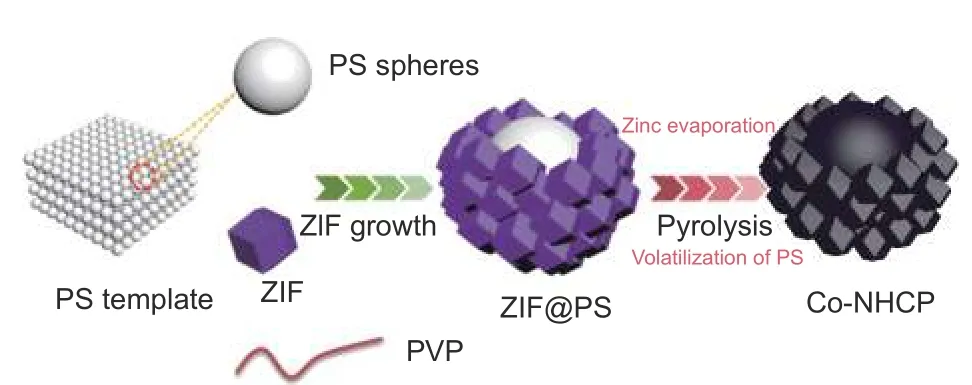
Scheme 1 Schematic diagram of the synthesis process of Co-NHCP
The synthesis strategy for Co-NHCP is schematically depicted in Scheme 1. The growth of ZIFs on the PS surface is achieved by a self-assembly techniqueviathe electrostatic force between Zn2+/Co2+and PS spheres. The surfactant PVP takes the lead role in the homogeneous growth of ZIFs particles. First,the negatively-charged PS spheres are enriched by PVP molecules to increase the electrostatic effect and provide sufficient coordination to adsorb Zn2+/Co2+on the surface of the PS spheres under the influence of static electricity. Immediately afterwards, the 2-MI is deprotonated to coordinate with zinc and cobalt ions to form nuclei, then the nuclei grow to form ZIF nanoparticles, and finally neutral 2-MI binds to positively charged ZIF terminate the reaction. The ingenious process of nucleation and crystal growth make it possible to achieve the coating of ZIFs on the surfaces of the PS spheres[38-39].
3 Results and discussion
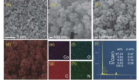
Fig. 1 SEM images of (a) PS, (b) ZIF@PS-2 and (c) Co-NHCP-2.(d-i) EDS elemental analyses of Co-NHCP-2
Fig.1a shows the SEM images of PS microspheres, having spherical shape with uniform size and distribution. The SEM image of ZIF@PS-2 (Fig. 1b)shows that ZIFs with an average diameter of about 100 nm are evenly wrapped on the surface of PS (200 nm). There is no agglomeration between the large core-shell structured particles or bare PS spheres were found. In sharp contrast, ZIF@PS-1 failed to form core-shell structure, ZIFs (1 μm) particles without wrapped PS (200 nm) spheres were produced, leaving bare PS spheres around the ZIFs, this may be due to the fact that the ZIFs size is much larger than the PS balls resulting in very few PS balls adsorbed on the ZIFs (Fig. S1a), whereas ZIF@PS-3 showed the clustered ZIFs (50 nm) wrapped around the PS ball(Fig. S1c). It is found that the agglomeration becomes more serious with the decrease of them(ZNH)/m(2-MI) ratio (Fig. S1e and S1g). It may be that the size of ZIFs keeps decreasing, but the overall electro-sorption capacity of PS ball remains the same, so the smaller size of ZIFs is more likely to be adsorbed on the surface of PS ball and produce more clusters. The formation of ZIF includes 2 processes: nucleation and crystal growth. First, the excess 2-MI is deprotonated to coordinate with zinc and cobalt ions forming nuclei, then the nuclei grow rapidly to form ZIF nanoparticles, and finally neutral 2-MI binds to positively charged ZIF and terminate the reaction. Excess 2-MI will adsorb on the surface of the nuclei and slow down the growth of the nuclei, so the particle size of ZIF decreases with the increase of 2-MI, which also leads to the decrease of the size of Co-NHCP and the content of cobalt[40-43]. These results indicate that the designed synthesis strategy for uniform growth of ZIFs particles on PS’s surface is feasible, and the synthesis process parameters have substantial effects on the morphology of the core-shell structured composites.Following thermal annealing at 900 °C for 5 h, the ZIF@PS-2 decomposed and formed spherical like large particles connected by carbonized ZIF structures, as shown in Fig. 1c. The composites maintain their original regular morphology and are well distributed whilst the Co-NHCP-1, Co-NHCP-3, Co-NHCP-4, and Co-NHCP-5 show serious agglomerations. The size of the particles is irregular and there are large spherical holes formed by the volatilization of the PS spheres on the surface (Fig. S1b, S1d, S1f and S1h). It can be concluded from the above results that with the increase of them(ZNH)/m(2-MI) ratio, the size of the synthesized ZIFs particles increases from tens of nanometers to greater than 1 μm. Therefore, the morphologies of the prepared materials change from agglomerated multilayer coating (Fig. S1g, S1e and S1c)to single-layer uniform coating (Fig. 1b) and then to the failure of coating (Fig. S1a). The Energy Dispersive Spectroscopy (EDS) results of Co-NHCP-2(Fig. 1d-h) indicate that all the elements are evenly distributed. Further semi-quantitative analysis shows that element Co in Co-NHCP-2 is 5.52% (mass fraction)(Fig. 1i).
The TEM images of Co-NHCP-2 are shown in Fig. 2a-c. It can be seen that ZIFs particles with uniform size were successfully prepared and uniformly covered on the surface of PS microspheres. After heat treatment, the core of PS spheres decomposed and formed spherical hollow structure with a uniform size of about 170 nm. The zoomed image shows that the ZIFs particles grew on the surface of PS microspheres presenting regular dodecahedral structures.There are no Co aggregates, suggesting that the Co atoms were evenly fixed in the carbon matrix. The cobalt atoms encapsulated by the N-rich carbon protective layer will allow the carbon layer to facilitate the passage of active species in all directions while inhibiting the large-scale oxidation and aggregation of cobalt atoms[36]. In addition, the encapsulation of the carbon layer will make the cobalt atoms more stable, thus improving the durability of the catalyst. The electron diffraction pattern of the ring-like selected area in Fig. 2d suggests that the fabricated Co-NHCP-2 catalyst has an amorphous structure. Moreover, the highresolution TEM (HR-TEM) images also confirm the hierarchical framework and high graphitic degree of Co-NHCP-2 (Fig. 2e-f). There are no signs of Co species and the lattice spacing suggesting that Co species may exist in amorphous form. The TEM EDS mapping results of single Co-NHPC-2 particles shown in Fig. 2g-j and Fig. S2 state clearly that N and Co are uniformly distributed in the carbon matrix material.Based on the above characterization results, it is further confirmed that hollow structure encapsulated by single-layer ZIFs was successfully synthesized.
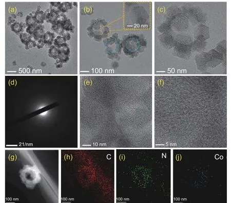
Fig. 2 (a-c) TEM images of Co-NHCP-2 at different magnifications;(d) SAED pattern of Co-NHCP-2; (e-f) HRTEM images of Co-NHCP-2;(g-j) TEM EDS elemental mappings of Co-NHCP-2
XRD analysis was conducted to measure the crystal structures and compositions of the prepared materials[44]. As shown in Fig. 3a, the wide diffraction peaks at 26.1° and 44.1° correspond to the (002) and(100) planes of graphitic structure (JCPDS Card No.41-1487)[39], respectively. No characteristic peak of Co crystal diffraction was observed in Co-NHCP-1 and Co-NHCP-2, indicating that the Co particles have a small size and even distribution, which is consistent with the structural analysis using TEM. However, the Co-NHCP-3 showed well-defined face-centered cubic Co peaks at 44.2° and 51.5°, which attribute to the agglomeration of ZIF@PS-3 during its synthesis process. The physicochemical properties of the as-prepared materials were also studied by Raman analysis(Fig. 3b). The Raman spectra of Co-NHCP-1, Co-NHCP-2 and Co-NHCP-3 all exhibit 2 strong peaks at 1 350 and 1 590 cm-1, denoted as theDandGbands of graphitic carbon material, respectively[45]. Integrated intensity ratio ofDband toGband (ID/IG) is usually used to estimate the defect density in graphitic carbon. Compared with Co-NHCP-3 (1.01) and Co-NHCP-1 (1.12), Co-NHCP-1 (1.12) has the highestID/IGratio, indicating that Co-NHCP-2 has higher degree of disorder and more defect structures. Since the periphery of Co-NHCP-2 is wrapped by uniformly dispersed ZIFs forming a thin graphitized carbon layer with a larger defect level and has hollow and hierarchical porous structure and large SSA, while Co-NHCP-3 is wrapped by heavily aggregated ZIF, the graphitized carbon layer of Co-NHCP-3 is thicker and has a lower defect level. That’s why theID/IGvalue of Co-NHCP-2 is obviously higher than that of Co-NHCP-3. The result of BET analysis in Fig. 3c shows that the SSA of the Co-NHCP-2 catalyst is 1 817.24 m2g-1, which is higher than Co-NHCP-1 (383.92 m2g-1) and Co-NHCP-3 (549.84 m2g-1). The high SSA of Co-NHCP-2 is attributed to its hollow structure formed after the pyrolysis of PS microspheres and the abundant pore structure formed after the decomposition of ZIFs. The relatively large particle size of Co-NHCP-2 could provide more internal pore structure, while the uniformly dispersed ZIFs at the periphery can also provide a certain surface area and pore structure. Because ZIF@PS-1 fails to form core-shell structure and shows large ZIF particles and bare PS spheres, its pyrolysis process involves separate decomposition of PS and ZIFs. The resulting Co-NHCP-1 is formed mainly by the pyrolysis of large particles of ZIFs, which exhibited minimum SSA. The SSA of Co-NHCP-3 is higher than that of Co-NHCP-1 but sharply lower than that of Co-NHCP-2, which may be ascribed to its core-shell structure and multi-layer coating structure of small ZIFs particles. Co-NHCP-3 has a small particle size and is tightly wrapped by a large number of smaller sizes ZIFs, resulting in undeveloped pore channels and small SSA. Catalysts presented type-IV curves with prominent hysteresis loops, demonstrating their mesoporous characteristics.Particularly, the Co-NHCP-2 shows well-developed microporous and mesoporous structure. The corresponding pore size distributions of the catalysts shown in Fig. 3d suggest the existence of a hierarchical pore structure, which is beneficial for charge and mass transport for electrocatalysis[46-47]. The macropores and mesopores can quickly transport and disperse reactants (hydroxyl ions and oxygen molecules) while the advantage of high void channel exposure of the micropores could facilitate electrolyte ion diffusion/penetration as well as gaseous product detachment, thereby improving the reaction rate during the catalytic process[48-49].

Fig. 3 (a) XRD patterns, (b) Raman spectra, (c) N2 adsorption-desorption isotherm curve and (d) the corresponding pore distribution of Co-NHCP-1, Co-NHCP-2 and Co-NHCP-3
XPS analysis of the catalysts was carried out to examine their elemental compositions and chemical states (Fig. 4, Fig. S3 and Fig. S4). As the survey XPS spectrum of Co-NHCP-2 reveals (Fig. 4a, Table S2),C (90.74%), N (5.28%), O (3.46%) and Co (0.52%)coexist in the sample, manifesting the efficient embedding of N and Co atoms into the carbon substrate.The doped N and Co can effectively modify the local electronic structure, change the surface property of the graphitic structures, and eventually enhance the catalytic property[50]. The high-resolution C 1s XPS spectrum can be deconvoluted into 4 peaks at 284.8,285.5, 286.6 and 288.7 eV, which are assigned to C—C, C=N, C—O and C=O, respectively. The emergence of the C=N bond further confirms that N is effectively doped into the carbon matrix (Fig. 4b).The deconvolution of the high-resolution N 1s XPS spectrum yielded 4 peaks at 397.6, 400.3, 402.4 and 404.6 eV, corresponding to pyridinic, pyrrolic, graphitic, and oxidic nitrogen, respectively (Fig. 4c). Notably, all the 3 samples have relatively high pyridinic-N contents, while the pyrrolic-N and graphitic-N contents of Co-NHCP-2 are significantly higher than those of Co-NHCP-1 and Co-NHCP-3 (Table S3). It has been reported that pyridinic-N, pyrrolic-N, and graphitic-N couldsignificantly contribute to the enhancement of ORR activity[51]. Pyridinic-N could greatly increase the spin density and π states density of the C atoms near the Fermi level, and anchor the Co sites by its high chemical stability, finally increasing the catalytic current density and theEonsetof ORR[52]. Pyrrolic-N not only modulates the adsorption energy of bonded metal atoms to O2, but also activates the adjacent C atom as the active site of ORR[53]. Graphitic-N is beneficial to improve the structural stability and the limiting current densities of carbonaceous materials[54], and can effectively promote the 4-electron reaction in the ORR process[55].The high-resolution scan of Co 2p comprises Co 2p3/2core level region and Co 2p1/2region (Fig. 4d). The fitting peaks at 778.8, 780.0 and 784.9 eV are ascribed to Co (0), Co (II) and Co-Nx, respectively[56]. The existence of Co (II) results from surface oxidation of Co and the carbon shell deposited on the Co surface[57-58].More critically, the abundant pyridinic N and graphitic N are believed to coordinate with Co to generate Co-Nxcoordination bonds, which are considered to be active sites for many electrocatalytic reactions[59].Taken together, the Co-NHCP-2 has graded porous structure that will enrich available active sites.
The water wettability tests show that the contact angles of Co-NHCP-1, Co-NHCP-2 and Co-NHCP-3 are 139°±2°, 143°±2° and 129°±2°, respectively(Fig. 5). During the ORR process, the water generated from O2reduction on catalyst’s surface and the water filled in the pores by diffusion from the electrolyte should be transported out of the porous channels in time. When lateral liquid water transport from catalyst layer through gas diffusion layer exceeds lateral water vapor transport in the gas flow channel of the bipolar plate, the flooding occurs[60], which leads to the interruption of oxygen supply to active sites in flooded area and the termination of ORR, which greatly influences the overpotential and reaction kinetics of fuel cells[61]. The highest contact angle of Co-NHCP-2 suggests that it can provide a smoother gas diffusion path to continuously transport the reactant oxygen to its active site and prevent the active site from being flooded by water[62].
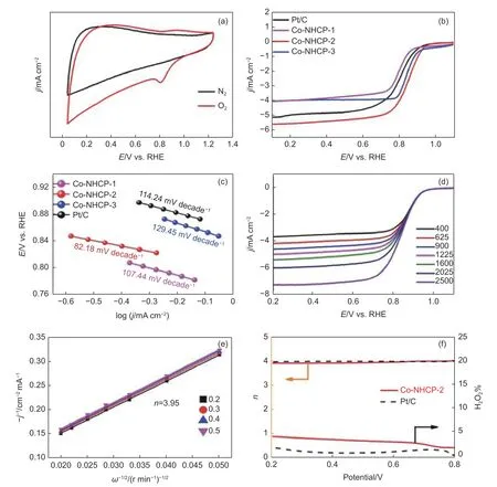
Fig. 6 (a) CV curves of Co-NHCP-2 on glassy carbon electrodes in O2 or N2-saturated 0.1 mol L-1 KOH. (b) LSVs of Co-NHCP-1, Co-NHCP-2, Co-NHCP-3,and 20% commercially available Pt/C catalyst in O2-saturated 0.1 mol L-1 KOH at a sweep rate of 5 mV s-1 at 1 600 r min-1. (c) Tafel slopes of Co-NHCP-1,Co-NHCP-2, Co-NHCP-3 and commercially available Pt/C catalyst. (d) Rotating-disk voltammograms of Co-NHCP-2 in O2-saturated 0.1 mol L-1 KOH with a sweep rate of 5 mV s-1 at different rotation rates. (e) K-L plots of Co-NHCP-2 at 0.2-0.5 V. (f) Electron transfer number (n) and H2O2 yield derived from the RRDE results
Cyclic voltammetry (CV) tests of the catalysts were performed in N2and O2-saturated 0.1 mol L-1KOH electrolyte on a rotating disk electrode (RDE) at a sweep rate of 5 mV s-1. The results are shown in Fig. 6a, S5a, S6a and S7a. The CV curves of the catalysts in N2-saturated electrolyte are virtually featureless, while their well-defined cathodic peaks for ORR emerged in O2-saturated electrolyte, indicating that the peaks in these tests were due to typical O2reduction.In general, a higher oxygen reduction peak potential means that the catalyst has a stronger ability to reduce O2and higher catalytic activity. Co-NHCP-2 shows more positive peak potential (0.84 V) than those of Co-NHCP-1 (0.78 V) and Co-NHCP-3 (0.80 V), implying the superior oxygen reduction capacity of Co-NHCP-2. The excellent electrocatalytic activity of Co-NHCP-2 was tested by linear sweep voltammetry(LSV) at 1 600 r min-1(Fig. 6b). In detail, Co-NHCP-2 exhibits extremely high ORR activity with the highestEonset(0.96 V) andE1/2(0.84 V), which are more positive than those of Co-NHCP-1 (0.90 and 0.78 V), Co-NHCP-3 (0.93 and 0.80 V), and commercially available Pt/C catalyst (0.95 and 0.82 V). Fig. 6c illustrates that the Co-NHCP-2 has smaller Tafel slope(82.18 mV decade-1) than those of commercially available Pt/C catalyst (114.24 mV decade-1), Co-NHCP-1 (107.44 mV decade-1), and Co-NHCP-3(129.45.44 mV decade-1) catalysts. The essential meaning of Tafel slope is the change of overpotential when the current density changes 10 times. The lowest Tafel slope of Co-NHCP-2 suggests that the overpotential change is smaller with faster current density increase (i.e., Co-NHCP-2 has the fastest reaction rate), indicating that the smaller tafel slope of the catalyst is critical for boosting the dynamic capability of oxygen reduction reaction[63-64]. In the mixed chargetransfer and diffusion controlled zone (below 0.9 V),where both kinetic and diffusion control are combined, the current density tends to increase with the rotating speed of the rotating disc electrode, indicating that the mass transfer rate of the reactants on the catalyst surface accelerates as the rotating speed of the rotating disc electrode increases. This phenomenon also indicates that the catalyst has the linear properties of porous channel carbon materials (Fig. 6d, S5b,S6b and S7b). In Fig. 6e, the Koutecky-Levich (K-L)curves of Co-NHCP-2 showed good correlation and parallelism at different voltage values, indicating that the concentration of O2dissolved in alkaline medium was closely related to the ORR. Since the 2e process is limited by poor electron transfer efficiency, low currents do not provide high cell power, and the resulting H2O2as an intermediate may corrode the catalyst and electrode devices, leading to shortened catalyst and electrode device lifetimes. Therefore, RDE tests were performed on Co-NHCP-2 and commercially available Pt/C catalyst to examine the H2O2yields in their 2e processes and to further determine the main reaction pathways for ORR. The reaction rates in this method exhibit primary reaction kinetics.The number of electrons transferred for Co-NHCP-2 was 3.95 in the voltage range of 0.2-0.5 V, which is close to the theoretical value of 4.0, indicating that the oxygen reduction reaction carried out on Co-NHCP-2 follows a 4e ORR path. The electron transfer numbers, H2O2yields of the prepared catalysts, and commercially available Pt/C catalyst were compared, as show in Fig. 6f, S5(d) and S6(d). Thenof Co-NHCP-2 remained 3.95-4 for potentials ranging from 0.2 to 0.8 V, similar to commercially available Pt/C catalyst.The trend for H2O2yield of Co-NHCP-2 is similar to commercially available Pt/C catalyst and H2O2yield of Co-NHCP-2 remained at a consistently low level of less than 5%. These results further verify the high selectivity toward 4e transfer pathway and the advantageous ORR performance of Co-NHCP-2, which was also similar to the RDE (Fig. 6e) test. Co-NHCP-2 with ZIFs as satellites have highly visible carbon edges providing a strong coupling interface between their O2species at the active site. This may be attributed to the excellent backbone structure of Co-NHCP-2 and the porous carbon material properties, which together provide a constant pathway for charge transfer from the catalyst during ORR through the presence of folded structures and porous channels. The relevant tiny openings are used for rapid transport of reactants and more efficient completion of the reduction reaction at the active site. As a result, electrolytes and dissolved oxygen can easily enter the catalytic active site, enhancing the adsorption, conversion and desorption capabilities of the Co-NHCP-2 in the ORR. A comparison of the electrochemical performances between the Co-NHCP-2 and the published studies using similar catalysts is listed in Table S5.
Methanol fuel cells have the advantages of low cost, high purity and high energy density, and the use of ORR catalysts in methanol fuel cells has good application prospects. However, the problem of methanol penetration from the anode to the cathode can greatly reduce the ORR activity and affect the fuel cell efficiency, which hinders the use of ORR catalysts in methanol fuel cells. Therefore, it is very important to study methanol resistance to determine the overall performance of ORR catalysts. Fig. 7a illustrates that the reduction current of Co-NHCP-2 was stable with only minimal fluctuation in response to the injection of methanol into the electrolyte at 300 s, but quickly recovered to that before methanol was added.The final current retention rate is 100% at 1 200 s. In contrast, the ORR current of commercially available Pt/C catalyst exhibits a sharp decrease with the addition of methanol and ends up with a rate of 61.23% at 1 200 s. Fig. 7b shows the catalytic ORR stabilities of the samples evaluated by chronoamperometry. The final current densities of the Co-NHCP-2 and commercially available Pt/C catalyst retained 98.53% and 75.72%, respectively, after running for 21 600 s. The Co-NHCP-1 and Co-NHCP-3 also show excellent methanol tolerance (Fig. S8) and good stability, and the current densities retain 91.31% and 92.42%, respectively (Fig. S9). Table S5 compares the ORR performance of this work with those of other reported catalysts under alkaline conditions. The Co-NHCP-2 catalyst in this work has relatively highEonset,E1/2and limiting current density, which is mainly due to the fact that Co-NHCP-2 has a good conformational relationship.
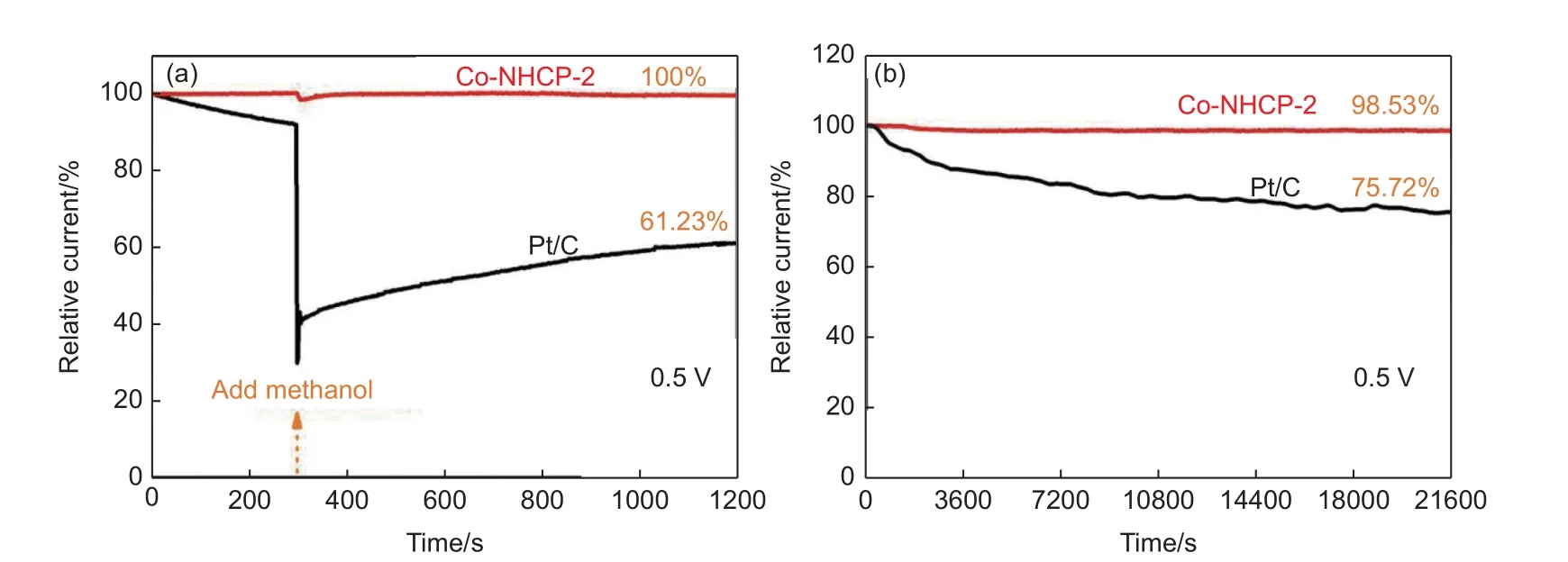
Fig. 7 (a) Chronoamperometric responses of Co-NHCP-2 and commercially available Pt/C catalyst by injecting 3 mL of 2% methanol at 300 s; (b) chronoamperometric responses of Co-NHCP-2 and commercially available Pt/C catalyst obtained under 0.1 mol L-1 O2-saturated KOH electrolyte at 1600 r min-1
The above electrochemical measurement results proved that the as-prepared Co-NHCP-2 has excellent ORR catalytic performances, which can be boiled down to the following reasons: (1) The hollow configuration with hierarchical porous structure of Co-NHCP-2 results in surprisingly large SSA and accordingly provides sufficient active sties and mass transfer channels, which promote the transfer of interfacial charge and mass transfer[65]. (2) The high contents of pyridinic N, pyrrolic-N, and graphitic N as well as the formation of Co-Nx-C coordination bonds could modify the local work function of the carbon atoms and optimize the adsorption energy of reactants. Besides, the Co atoms can improve the charge transfer of the electrode and significantly increase the current intensity[66-67]. (3) The relatively high hydrophobicity of Co-NHCP-2 is conductive to the diffusion and transportation of oxygen to its surface, and helps prevent the active site from being flooded by water.(4) The graphitic carbon in the catalyst and the existence of the Co-Nx-C coordination bond effectively inhibit the corrosion of the the catalyst, and the low H2O2yield reduces the oxidation of the active metal components, thereby ensuring the stability of the catalyst[68-76].
4 Conclusion
A facile approach to synthesize core-shell-structured ZIFs@PS materials which can be further converted into M—N—C electrocatalyst with hollow and hierarchical porous structures through one-step pyrolysis was developed. The as-prepared catalyst Co-NHCP-2 not only possesses high surface area up to 1 817.24 m2g-1and a hierarchical porous structure,but also provides high contents of pyridinic-N, pyrrolic-N, graphitic-N, and uniform Co distribution without agglomeration. The electrochemical results show that the Co-NHCP-2 has good performance as a highly efficient and durable ORR catalyst for fuel cells. TheEonset,E1/2, and limiting current density reaches 0.96,0.84 V, and 5.50 mA cm-2, respectively, and the current retention rate remains at 98.53% after running for 21 600 s. The Co-NHCP-2 also has low H2O2yield of less than 5%, excellent methanol resistance, and exceptional selectivity toward 4e pathway. In summary,this work provides a simple and attractive method to prepare hierarchical porous M—N—C ORR catalyst with large specific surface area and may be easily extended to other porous carbon hybrid materials for energy related applications.
Acknowledgements
This work was financially supported by the National Natural Science Foundation of China(U1703251, U1810113). We thank Dr. Fumin Guo from University of Toronto for his linguistic assistance during the preparation of this manuscript.
- 新型炭材料的其它文章
- Large-scale synthesis of 3D ordered microporous carbon at low temperature using cobalt ions exchanged zeolite Y as a template
- Reversible surface modification of PAN-based carbon fibers by a ferrocene-based surfactant
- Recent advances in 3D interconnected carbon/metal high thermal conductivity composites
- Development of biochar electrode materials for capacitive deionization: preparation, performance, regeneration and other challenges
- Synthesis and electrochemical properties of nano-Si/C composite anodes for lithium-ion batteries
- Factors that influence the performance of hydrogen detectors based on single-wall carbon nanotubes

