Recent advances in 3D interconnected carbon/metal high thermal conductivity composites
GUAN Hong-da, HE Xin-bo,2,*, ZHANG Zi-jian, ZHANG Tao,2, QU Xuan-hui
(1. Institute for Advanced Materials and Technology, University of Science and Technology Beijing, Beijing 100083, China;2. Guangzhou Institute of Advanced Materials, University of Science and Technology Beijing, Guangzhou 510320, China)
Abstract: As the temperature of electronic devices continues to rise, the quest for high-efficiency heat dissipation has emerged as a critical concern, particularly when it comes to ensuring device performance and longevity. A high thermal conductivity is usually dependent on the ability of fillers to provide thermal conduction channels within composites. In recent years, the development of three-dimensional (3D) interconnected structures using high thermal conductivity fillers in composites has emerged as a promising approach. Compared to the traditional isotropic distribution and directional arrangements, 3D interconnected filler structures improve the thermal conductivity. We review research progress on metal matrix composites with a 3D interconnected carbon filler that have a high thermal conductivity. The thermal conductivity mechanisms and models of composites are elaborated, and important factors relevant to improving the thermal conductivity are considered. Ways of constructing 3D interconnected carbon networks and their effects on the thermal conductivity of their composites should serve as a reference for the advancement of high-performance metal matrix thermal conductivity composites.
Key words: Carbon filler;3D interconnected networks;Metal matrix composites;Thermal conductivity;Preparation method
1 Introduction
As the 5G era progresses, intelligent functions of electronic devices constantly increase[1-2]. Thinness,integration and multi-function have intensified the heat generation of electronic devices, which is followed by the heat dissipation problem[3-5]. Efficient heat dissipation can maintain the best performance and service life of electronic devices, thus improving product stability and reliability[6-8]. Electronic packaging materials play a crucial role in effective heat dissipation as they require higher thermal conductivity for efficient thermal management. Additionally,better thermal matching with semiconductor materials is needed[9]. Although metal packaging materials such as Al, Cu, and Ag exhibit excellent thermal conductivity[10-11], their high coefficient of thermal expansion makes them difficult to match with semiconductor devices[12-13]. Later-developed W/Cu and Mo/Cu have excellent thermal physical and mechanical properties,but low thermal conductivity and high coefficient of thermal expansion limit their usefulness for microelectronics technology[14-15]. Given these limitations,the demand for composites with comprehensive thermal properties has grown and gradually replaced traditional metal packaging materials as promising thermal management materials[16-17].
Metal matrix thermal conductivity composites frequently combine the strengths of high thermal conductivity fillers and metal matrix materials, so as to achieve the effect of functional and performance designability[18]. Carbon materials are considered ideal reinforcement candidates due to their high intrinsic thermal conductivity[19]. Additionally, they meet the development requirements of the next generation of electronic devices which integrate functionalization,miniaturization, and thinness[20]. In order to meet the various demands of technological advancements, carbon materials are designed into various forms including graphite (graphite particles, graphite flakes, graphite foam), carbon fiber, carbon nanotubes (CNT),graphene, and diamond[21-25]. Recently, carbon/metal composites have been rapidly developing in the direction of high heat dissipation, low thermal expansion,high strength, and toughness.
Although many studies have reported that carbon filler reinforced metal matrix composites, their thermal conductivity is far lower than expected[26].The thermal conductivity of the metal material depends on the movement of electrons. The thermal conductivity mechanism in non-metallic crystals or ceramics is generated by phonons, which depends on the atomic mass, interatomic bonding and crystal structure[17]. A structural mismatch of vibration energy transfer between carbon materials and metals leads to phonon scattering at the interface that restrains the efficient enhancement of thermal conductivity[27]. Interfacial modification is considered to be an effective way to enhance the thermal conductivity of composites[28]. However, the uniformly dispersed carbon fillers prevent the formation of an effective heat transfer network, thereby resulting in significant thermal resistance at the filler-matrix interface[29]. Although interface modification improves the interface bonding, it has a limited effect on improving the thermal conductivity. To improve the thermal conductivity of composites, it is crucial to achieve the connectivity of fillers[30]. Therefore, researchers have developed the directional heat dissipation model of carbon filler. For example, electric field and freezedrying can be used to realize efficient directional heat dissipation of carbon fibers in the composites[31-32].However, there are observable disparities between axial and radial thermal conductivity. Thus, controlling the spatial distribution of fillers in composite configuration is essential to improving the thermal conductivity of the composites.
Three-dimensional (3D) interconnected carbon structures are promising heat transfer models for the preparation of high thermal conductivity composites,because they can provide a large number of rapid thermal conductivity channels. Their unique performance has led to extensive study in the fields of efficient thermal management and energy conversion in recent years[33-35]. 3D interconnection networks of carbon materials (such as diamond, carbon fibers,graphene, CNT and graphite) formed by self-connection, binder connection, foam formwork and templatedirected chemical vapor deposition (CVD) have become a more efficient way to prepare high thermal conductivity composites than composites reinforced with dispersed fillers[36-38]. Constructing 3D interconnected carbon material networks in the metal matrix allows for most of the heat transfer to occur through the carbon material networks, which reduces heat transfer loss at the carbon/metal interface. In addition to providing continuous and efficient heat transfer channels, 3D interconnection network also enables the composites to have isotropic thermal conductivity. By combining the structural advantages of 3D interconnected networks and the superior thermal conductivity of carbon materials, it can be expected that the thermal conductivity of the 3D interconnected carbon material networks reinforced metal matrix composites will be significantly enhanced.
This paper presents a comprehensive review of the research progress on 3D carbon materials reinforced metal matrix thermal conductive composites.First, the heat conduction mechanism of metal matrix composites, along with the factors that influence the thermal conductivity of composites with 3D interconnected fillers, is delineated. Second, the construction of 3D carbon materials with high thermal conductivity is introduced, while exploring the relationship between material composition, structural characteristics, and thermal conductivity in each construction method. Finally, future research and development of 3D carbon materials reinforced metal matrix composites are prospected.
2 Heat transfer in metal matrix composites
2.1 Thermal conduction mechanisms
The essence of heat transfer is the outward propagation of the kinetic energy of molecules, atoms and electrons inside an object. As we all know, the 3 basic forms of heat transfer include heat conduction,heat convection and heat radiation[39]. Among them,thermal conduction caused by particle collisions is the main mode of heat transfer in solid matter (Fig. 1a).Thermal conduction refers to the transfer of a particle’s vibrational energy to adjacent particles without any movement of matter, mainly through collisions. Lattice vibration and free electron migration are 2 forms of thermal conduction in solids. Thermal conduction in metallic materials is determined by free electrons,while thermal conduction in non-metallic materials is determined by lattice vibrations. Phonons, as quanta excited by lattice vibrations, are thermal carriers in nonmetallic materials. Thermal conductivity dominated by lattice vibrations can be estimated theoretically using the Debye equation[40]:
whereCpis the specific heat capacity per unit volume,vis the average phonon velocity, andlis the phonon mean free path.
Thermal conductivity in metals is mainly due to electrons, so there is a proportional relationship between thermal conductivity and electrical conductivity. The thermal conductivity in metals has been established according to the Wiedermann-Franz law[41]:
where L0is the Lorentz constant (L0= 2.44 × 10⁻⁸ΩW K-2),σeandTare the electrical conductivity and temperature, respectively.
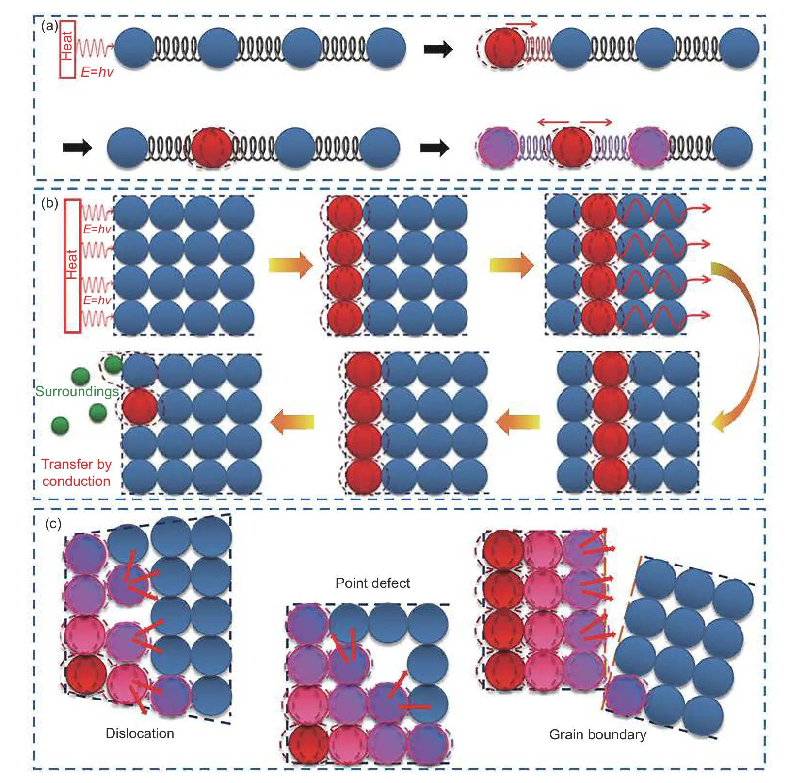
Fig. 1 (a) Thermal conduction in matter by collision of particles. (b) Thermal conductivity mechanism in a crystalline material. (c) Phonon scattering in crystalline materials, due to various defects[41]. Copyright 2016 Elsevier Ltd.
Highly crystalline materials generally have high thermal conductivity, such as metals, graphene and diamond[42-44]. This is because crystalline materials have a long-range ordered structure compared to amorphous materials, resulting in less phonon scattering generated by lattice vibrations. Understanding the basic thermal conductivity mechanism in crystalline materials is the premise of studying the thermal conductivity of composites. Fig. 1b shows the thermal conduction mechanism of materials with crystal structure. Surface atoms acquire thermal energy and pass it on to adjacent atoms. Then, the heat energy is sequentially transferred to diffuse in the sample until it is transferred to the surrounding environment. The thermal properties of the metal matrix composites are mainly determined by the metal matrix, filler and their interfacial bonding. To enhance the thermal conductivity of composites, fillers with higher thermal conductivity than the metal matrix are typically incorporated. Therefore, interface bonding is the key factor affecting the thermal conductivity of composites. The mismatch between non-metallic filler and metal matrix at the interface causes phonon scattering. Phonon scattering changes the direction of heat transfer, and the resulting interfacial thermal resistance severely reduces the thermal conductivity. Phonon scattering includes three mechanisms: phonon-defect scattering,phonon-phonon scattering and phonon-interface scattering[45]. The defects in the crystal structure serve as barriers for phonon transfer, resulting in scattering called phonon-defect scattering, as shown in Fig. 1c.Not all atoms in the material vibrate together at the same frequency, and these multiple frequencies produce phonon-phonon scattering. There are inevitable interfaces between different materials, so phonon-interface scattering is the main mechanism in composites[46].
The thermal conductivity of composites depends significantly on the interface configurations of the 2 components. In traditional 0D fillers, the distribution takes the form of a “sea-island” within the composites[47]. The high number of mismatched interfaces leads to enhanced phonon scattering, which results in increased interface thermal resistance and limits the improvement of thermal conductivity. When fillers come into contact with each other, thermal conduction primarily travels along the interconnected fillers rather than the matrix[48]. The thermal resistance between fillers is lower than that at the filler/matrix interface, resulting in improved thermal conductivity when the connectivity between fillers is established within the composite. 1D fillers can be constructed into linear heat transfer channels. 2D fillers can be constructed into planar heat transfer channels. 3D fillers can be constructed as heat transfer channels for interconnected networks. In theory,different dimensional fillers exhibit different thermal conduction efficiencies, with 3D fillers being the most efficient, followed by 2D and 1D fillers. This is due to the fact that the 3D network structure of the filler increases the heat transfer path[20]. Fig. 2 shows the composition, structure model and heat transfer path of 0D-3D carbon filler/metal thermal conductivity composites. Furthermore, the low interfacial thermal resistance between interconnected fillers decreases phonon scattering, resulting in improved thermal conductivity of the composites.
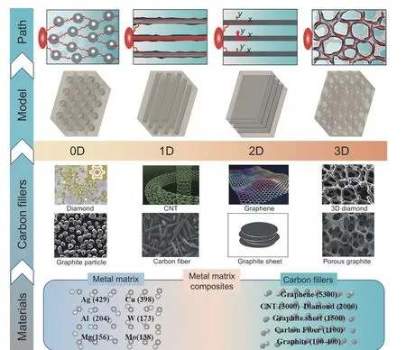
Fig. 2 Composition, structure model and heat transfer path of 0D-3D carbon filler/metal thermal conductivity composites[5].Copyright 2020 Elsevier Ltd.
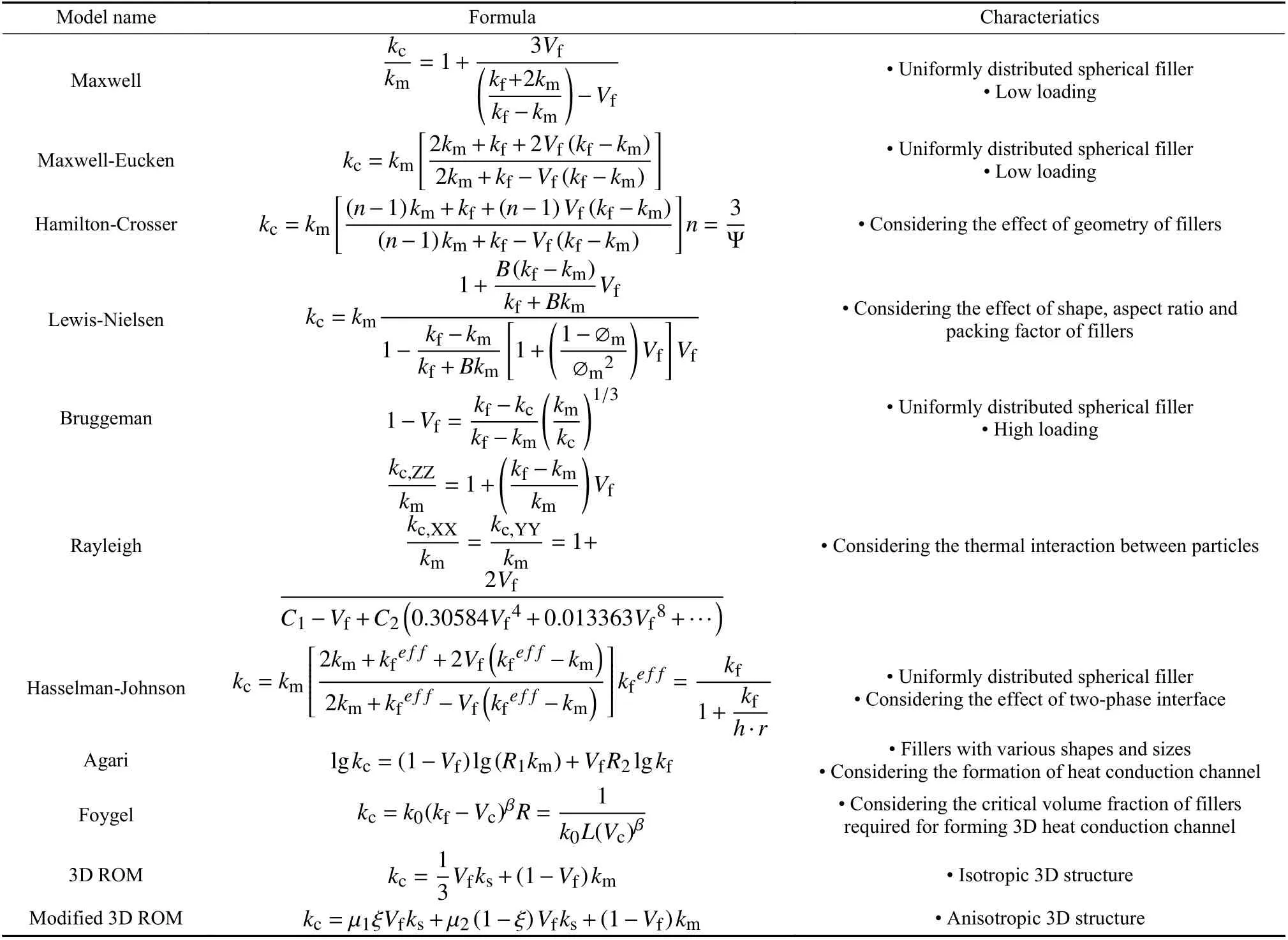
Table 1 Summary of theoretical models for predicting the thermal conductivity of composites
Theoretical models play a critical role in predicting the thermal conductivity of composites. Table 1 summarizes important models used to predict the thermal conductivity of composites[17,45,49-51]. For composites with 0D fillers, the Maxwell model is the first to predict the effective thermal conductivity of randomly distributed spherical particles in the continuous matrix. Nevertheless, the model neglected the thermal regime interactions between the spherical particles, making it only suitable for low-filler volume fractions (less than 25%). Subsequent work has developed more precise prediction models based on the Maxwell model. The Maxwell-Eucken model, appropriate for uniformly distributed spherical fillers, can calculate multiple different filling particle phases within a single matrix[52]. Additionally, the Hamilton-Crosser model adjusted the Maxwell model to make it suitable for composites containing fillers of different shapes[53]. The Lewis-Nielsen model, designed for medium filler volume fractions (approximately 40%),further considers the impact of filler shape and aspect ratio[54]. In contrast, the Bruggeman model, also called differential effective medium theory, provides more accurate predictions for composites with high filler volume fractions, covering multi-component systems calculation formulas[55].
The thermal conductivity of composites reinforced by 1D fillers can be modeled using the Rayleigh model, which describes a continuous matrix reinforced by parallel cylindrical fibers (Fig. 3)[56].The Rayleigh model can be simplified to the Maxwell model when thermal interactions between particles are neglected, and the predicted thermal conductivity of composites by the Rayleigh model is related to the direction of the filler. The Rayleigh model is important for understanding the thermal conductivity model of composites reinforced by 1D filler.
On the other hand, for composites reinforced by 2D fillers, the Hasselman-Johnson model, based on the Maxwell and Rayleigh models, is introduced[57].The Hasselman-Johnson model comprehensively considers filler volume fraction, filler shape, interfacial gaps between fillers and matrix, and interfacial thermal resistance. The model establishes a connection between the effective thermal conductivity and the filler particle radius (r) and the interfacial thermal conductivity (h). Hasselman-Johnson model can predict the thermal conductivity of a continuous matrix reinforced by spherical particles, rod-shaped fibers,and flake fillers, respectively. When considering only one shape of filler, the Hasselman-Johnson model can be simplified to the Maxwell model for spherical particles and the Rayleigh model for rods perpendicular to the heat flow. Additionally, Thomas and Hasselman incorporated the effect of interfacial gap between fillers and matrix on the thermal conductivity of the composites in the Hasselman-Johnson model[58].
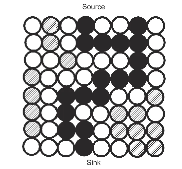
Fig. 4 Schematic diagram of partially connected channels formed by fillers in composites. Black particles represent the fillers that form a continuous heat transfer channel from source to sink. White is for matrix particles, and hatching is for the fillers which do not form a continuous channel[50]
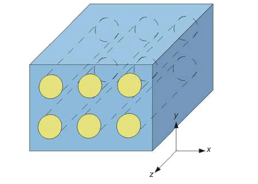
Fig. 3 Schematic diagram of Rayleigh model, consisting of parallel cylinders embedded in a continuous matrix[50]
2.2 Thermal conductivity model of composites containing 3D-structured fillers
Increasing the volume fraction of fillers in a matrix can enhance the connectivity of some filler particles. Such filler particles with high thermal conductivity are preferred for thermal conduction, and the interface between fillers greatly reduces the interface thermal resistance compared with the filler-matrix interface. When the filler volume fraction is sufficient,the filler particles may self-organize into a continuous channel from source to sink, resulting in thermal conductivity channels that enhance the effective thermal conductivity of the composites (Fig. 4). Numerical simulation is an effective method for predicting the impact of heat transfer channel formation on the effective thermal conductivity in composites[59]. Numerical simulation combining partial connected sum interface thermal resistance can predict the thermal conductivity of the composite. The finite element method(FEM) is commonly used to predict the thermal conductivity of composites containing fillers with complex shaped[60]. However, the FEM requires a long simulation time to process complex models.
To accurately predict the thermal conductivity of composites containing 3D fillers, it is crucial to form more heat transfer channels among the fillers. The Agari model introduces a parameter to represent the number of thermal conduction channels to predict the thermal conductivity of composites with high filler volume fraction[61]. The Foygel model simulates the threshold for the formation of 3D thermal conduction channels in composites and obtains the critical volume fraction of fillers required for the formation of thermal conduction channels[62]. Additionally, the 3D rule of mixtures (ROM) model, derived from the metal foam theory that considers filler and matrix as 2 continuous phases, can be used to predict the thermal conductivity of such composites[63]. The 3D rule of mixtures(ROM) model has been found to be effective in predicting the thermal conductivity of composites for thermal conduction channels formed by isotropic 3D structured fillers. To further enhance the applicability of this model, a modified 3D ROM model is proposed, incorporating filler orientation and concentration parameters[64]. This modification allows for the simulation of thermal conductivity in composites with anisotropic 3D fillers.
2.3 Factors affecting the thermal conductivity of 3D interconnected fillers reinforced composites
Enhancing the thermal conductivity of composites requires the establishment of effective heat conduction channels through the use of fillers in the matrix. Initial attempts focused on increasing the filler volume fraction to ensure filler connectivity, but the thermal conductivity improvement was not significant. With the increase of filler volume fraction, the interfacial thermal resistance of filler-filler and fillermatrix interfaces also increases. In contrast, the use of 3D interconnected fillers is a viable approach for decreasing interfacial thermal resistance by offering numerous phonon transfer paths[65]. For fillers with the same volume fraction, the thermal conductivity of the composites with 3D interconnect fillers will be improved.
Construction of 3D interconnected fillers often involves fabrication using different template methods before filling the matrix into the 3D preform. The fillers create a double connected structure with the matrix, which boosts composite thermal conductivity and preserves other excellent properties. Optimization of structural design parameters, such as filler content, pore size, shape, multiphase hybridization, interface bonding, and secondary networks, is necessary for improving the thermal conductivity of composites containing 3D fillers[49,66]. Compared with uniformly dispersed fillers, 3D interconnected fillers with the comparable content can form more efficient conduction channels to improve the thermal conductivity. It is an appropriate way to construct 3D interconnected fillers with high volume fraction through high density templates[64]. The thermal conductivity of composites is also influenced by the pore size of 3D interconnected fillers. Larger pore sizes can reduce the interfacial contact area between fillers and matrix, thereby decreasing interfacial thermal resistance for enhanced thermal conductivity. However, they can also limit filler volume fraction and affect the support strength of 3D interconnected fillers. Additionally, the shape of the filler is a significant factor affecting interfacial thermal resistance between fillers. Particle, fiber and flake fillers correspond to point, line and surface contact, respectively[67]. As point contact does not facilitate effective heat transfer among thermal-conductive fillers, multiphase filler hybridization is often employed to improve thermal conductivity. The flake filler is an ideal hybrid filler due to its larger contact area[68]. It is important to note that fiber and flake fillers are anisotropic and thus, the orientation of fillers must be considered when constructing 3D structures to improve thermal conductivity in the desired direction. The hybrid of large and small fillers is another approach used to construct 3D structural networks. The large size filler forms the main thermal conduction channel of the 3D structure, while the small size filler forms a secondary network within the hole. The secondary network provides a great advantage in synergistic enhancement by increasing both the heat conduction channels and the filler content[69]. In 3D structures, the physical contact between fillers is usually weak, leading to unfavorable interface thermal resistance. To enhance thermal conductivity, one effective strategy is to improve the bonding strength at the filler-filler interface. Covalent bond modification of the filler allows undamaged phonons to propagate along the filler network, which leads to increased thermal conductivity. Moreover, continuous covalently bonded fillers can be prepared by chemical vapor deposition for significant reduction of thermal resistance at the filler-filler interface[5]. The interfacial thermal resistance between filler and matrix can be reduced by coating the fillers and alloying the matrix. In general, optimizing the microstructure of 3D interconnected fillers is one of the main approaches to develop high-performance thermal conductive composites.
3 Construct 3D carbon filler network in metal matrix composites
Due to the various shapes (particles, fibers and sheets) and sizes (nanoscale and micrometer-scale) of different carbon fillers and methods are required to construct 3D interconnected structures with continuous heat transfer networks for various types of carbon fillers. 3D interconnected carbon filler can be constructed in metal matrix composite in 2 forms: Direct interconnection of carbon fillers during composite preparation and pre-construction of 3D carbon fillers followed by composite formation with the metal matrix. The construction methods of 3D interconnected carbon fillers include self-connection, binder connection, foam formwork and template-directed CVD method. By controlling process parameters, orderly stacking of carbon fillers in composites can be achieved. The relationship between material composition, structural characteristics, and thermal conductivity in each construction method will be discussed in the following sections.
3.1 Self-connection
In composites, the fillers bridge each other to form the 3D continuous skeleton, which is called selfconnection. This process requires fillers with a larger particle size, high volume fraction, and adequate strength to ensure the skeleton’s stability and prevent its collapse when filling the matrix. The larger particle size promotes the formation of larger pores, which facilitates better infiltration of the matrix. Moreover, the higher volume fractions of the fillers enhance thermal conductivity by providing more channels for heat transfer[70-71]. Furthermore, the connection between the fillers reduces interface thermal resistance and establishes 3D high-speed thermal conduction channels that run throughout the matrix.
Diamond particles, with their excellent thermal conductivity, satisfy the above requirements and have drawn attention from early researchers as potential fillers[72-73]. Diamond reinforced metal matrix composites, especially Cu matrix, have ultra-high thermal conductivity. Through the high-pressure infiltration process, diamond/Cu composites with thermal conductivity values as high as 742 W m-1K-1have been prepared, surpassing the theoretical value predicted by Hasselman’s equation[74]. This increased thermal conductivity is due to the orderly arrangement of diamond particles at higher volume fractions, resulting in the formation of interconnected skeleton (Fig. 5a). Cu is filled in the gap between diamond particles, thus forming a double-connected network structure. In this structure, part of the diamond/Cu interface is replaced by the diamond/diamond crystal interface, effectively reducing interfacial thermal resistance. During the preparation of diamond/Cu composites, the diamond interconnection network is formed, and this work demonstrates the positive effect of this network on the thermal conductivity of diamond/Cu composites.
To verify the positive effect of interconnected network on the thermal performance of composites,diamond particles with larger size and higher volume fraction were attempted to further improve the connectivity of diamond particles. Ekimov et al. prepared diamond/Cu composites with thermal conductivity up to 900 W m-1K-1) using diamond particles (200 μm)with 95% volume fraction by ultra-high pressure[36].The results indicate that the network skeleton formed by 200 μm or more diamond particles play an important role in the high thermal conductivity of the composites. The connection between diamond and diamond constitutes the continuous thermal conductivity channels, which greatly improving the thermal conductivity of composites compared to those without diamond channels (Fig. 5b).
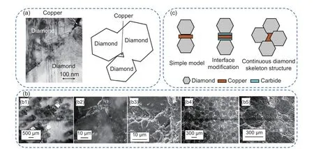
Fig. 5 Construction of diamond interconnection network. (a) Diamond forms locally connected structure in copper matrix[74]. Copyright 2004 Elsevier Ltd.(b) Microstructure studies have found the formation of diamond frameworks[36]. Copyright 2008 Elsevier Ltd.(c) Thermal conductivity channel model of diamond/Cu composites
The construction of continuous diamond reinforced Cu matrix composites has been further studied.In particular, Zhang et al. prepared diamond/Cu composites, in which continuous diamond particles act as effective thermal conductivity channels[75]. The results indicate that the diamond particles form chemical bond by direct contact under high temperature and high pressure. Despite not being a true chemical bond,the mechanical parameters of the contacting lattices are similar, and they exhibit good lattice vibration coupling. This leads to a small interface thermal resistance, and the formation of diamond skeleton with a certain gap. Cu is squeezed into these gaps under high temperature and pressure, which helps to maintain the stability of the diamond skeleton (Fig. 5c). The authors also conducted theoretical modeling to examine the relationship between thermal conductivity and microstructure. In dispersed diamond/Cu composites, the effective thermal conductivity channels exist in the form of a simple diamond-Cu-diamond model. Due to the non-wetting between diamond and Cu, the bonding strength is weak. When the lattice vibration travels to the interface of diamond and copper, it will reflect due to the serious impedance mismatch and produce great thermal resistance. To address this issue, carbide transition layers are commonly formed at the interface to enhance the chemical bond strength of the CCu interface. Nonetheless, the thermal conduction mechanism of inorganic non-metal differs from that of metal. On a theoretical level, the heat conduction efficiency between Cu and the carbide transition layer is expected to be low, and achieving an ideal transition layer in the manufacturing process can be challenging.The preferred thermal conductivity model involves a continuous diamond skeleton structure, where the effective heat transfer channel mainly relies on diamond particles. This is due to the diamond-diamond interface exhibiting stronger interaction, better lattice vibration coupling, and lower thermal resistance.
Self-connection is a viable method for producing large-sized and high-volume fraction diamond network structures. However, the higher volume fraction of diamond may result in increased composite costs and reduced machinability. Additionally, it should be noted that not all diamond particles in the composite are connectedviaself-connection, only the majority.Nevertheless, the simplicity of the self-connection method is advantageous for constructing a network structure.
3.2 Binder connection
Diamond, as a 0D carbon material, has the unique capability of self-connection to form a network skeleton under pressure. However, when it comes to 1D carbon materials like carbon fibers, selfconnection is infeasible. Adding binders can make carbon fibers form interconnected network structure.The preparation of carbon fiber interconnected network is a key step in the production of composites.Surface cracks, fiber fracture damages, uneven fiber distribution and other defects, as well as the subsequent drying and sintering processes, are a few prominent factors that affect the performance of carbon fiber networks.
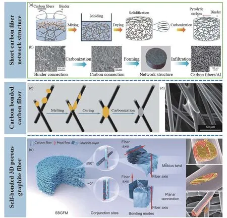
Fig. 6 Construction of 3D carbon fiber network by binder connection. (a) Flowchart of preparing short carbon fiber network structure[79]. Copyright 2019 Elsevier Ltd. (b) Microscopic images of carbon fiber network structure[76]. Copyright 2012 Springer Nature. (c) Diagram of the formation of carbon bonded carbon fiber. (d) Microscopic picture of carbonaceous bond point[77]. Copyright 2018 Elsevier Ltd. (e) Self-bonded 3D porous graphite fiber monolith using asphalt as binder[78]. Copyright 2022 Elsevier Ltd.
Diverse interconnected carbon fiber networks,constructedviadifferent binder types, have been studied to date. Liu et al. introduced a novel binder and degreasing process suitable for the preparation of short carbon fiber network structures, thereby providing new ground for preparing composites reinforced with short carbon fibers[76]. The short carbon fiber network was prepared through a wet-forming method and the process diagram is represented in Fig. 6a. The carbon fibers are first dispersed in a liquid binder, the solvent is dried and poured into a mold to be molded.After drying and degreasing, the carbon fiber network structure is obtained (Fig. 6b). Jiang et al. prepared the carbon bonded carbon fiber network structure using graphite fibers with high thermal conductivity[77].They bonded random carbon fibers with phenolic resin binders and obtained a stable network structure post-carbonization. The bonding process is illustrated in Fig. 6c. The phenolic resin powders were evenly dispersed on top of the carbon fiber surface through solvent. As the phenolic resin melts at elevated temperatures, it moves along the fiber surface and connects contiguous fibers in contact with each other.Following carbonization, the phenolic resins were transformed into pyrolytic carbon, thereby resulting in a stable network structure of the carbon fibers(Fig. 6d). Jiang et al. prepared a self-bonded 3D porous graphite fiber monolith (SBGFM) using asphalt with the same composition as carbon fiber as the binder[78]. The bonding mode at the fiber contact area was examined, and a thermal conductivity model for SBGFM was proposed as represented in Fig. 6e. Based onα, the intersection angle, two different bond types exist among neighboring carbon fibers (α= 0° andα≤90°). Interestingly, regardless of the change in bonding angle, the internal chips from 2 contiguous carbon fibers almost always connect at the edges to form a broad plane. In the case ofα= 0°, the carbon layers from 2 aligned fibers grow into the same plane along the edge at the interface. Forα≤ 90°, the layer coalescence pattern can be comprehended as resembling Mobius strip when accounting for the formation of mesophase pitch layer twist disclinations. The aromatic polymerization between 2 assemblies of crystallite lamellae always proceeds edgewise. The graphite crystal structures are continued at the interface, promoting the axial path of phonon transfer and thereby effectively increasing the thermal conductivity.
The advantages of carbon fiber networks include provision of unceasing and effective heat conduction paths, as well as dimensional stability and lightweight properties. The direct inter-fiber contact significantly decreases the interfacial thermal resistance, thus enhancing the thermal conductivity of the composites.The binder connection process is budget-friendly, uncomplicated, and easy to expand. In addition, it is essential to optimally design the pore size, strength, and interface modifications of the carbon fiber bonded network for improved matrix infiltration.
3.3 Foam formwork
As an example, 3D CNT/Cu composite foam was synthesized by electroless plating-electrodeposition using melamine foam as the template[38]. CNT was deposited on the foam framework during Cu electroplating. The melamine template was later eliminated by high-temperature sintering to obtain 3D CNT/Cu composite foam, and Cu powders were filled into the composite foam to obtain 3D CNT/Cu composite(Fig. 7a). Another study reported on the utilization of polyurethane (PU) foam as a template to prepare a graphite foam modified by multi-walled CNT through the impregnation-pyrolysis method (Fig. 7b)[80]. PU foam was immersed in mesophase pitch/multi-walled CNT slurry, dried, heat-treated, carbonization and graphitization to ultimately obtain multi-walled CNT/graphite foam. The highly graphitized structure makes CNT/graphite foam have high thermal conductivity. The 3D skeleton provides a mechanism for continuous heat conduction, thereby considerably improving the thermal conductivity of the composites. In another study, the 3D graphite network was constructed using PU foam as a template and graphite slurry uniformly coated on its surface through impregnation[81].Cu/graphite composite with a 3D double continuous structure of graphite phase and Cu matrix were developed by filling Cu powder in the graphite skeleton(Fig. 7c). The use of a 3D double continuous structure enabled the enrichment state and distribution form of the graphite phase to be effectively improved,thus providing a novel option for designing high thermal conductivity carbon/metal composites. Furthermore, Karthik et al. used PU foam as template to prepare graphite foam by slurry impregnation method(Fig. 7d)[82]. The results show that the well dispersed metal particles in the carbon matrix can be used as catalysts to transform amorphous carbon into welldefined graphite carbon.
To ensure optimal infiltration of the matrix, it is critical to choose foam templates with appropriate pore sizes. The continuous filler network established by the foam template method depends on the uniform deposition and load of filler on the template. Before impregnating the matrix, polymer templates need to be removedviahigh-temperature treatment to prevent any adverse effects on the performance of the composites. Therefore, after removing the polymer template, the 3D filler network needs to have a certain strength to support the infiltration of the matrix. To further improve the thermal conductivity of composites, constructing a secondary network in the 3D filler skeleton is also an effective means.
3.4 Template-directed CVD
CVD is a widely used technique for preparing metal matrix composites by gaseous method. The CVD process involves the deposition of a solid substance onto a substrate through a gaseous chemical reaction of gaseous precursor. CVD is useful for depositing layers of various materials such as metals, alloys,ceramics, and carbon materials. The technique enables control over the density, purity, and gradient deposits of coatings, while coatings can be deposited on complex shapes and porous substrates. The 3D structure produced by template-directed CVD exhibits seamless connection and provides continuous phonon transmission channels. Moreover, carbon materials grown by CVD have fewer structural defects and better crystal structure, as compared to other methods.The 3D network constructed by template-directed CVD can more effectively improve the thermal conductivity of the composites.
Carbon-metal interface wettability is usually unfavorable, which makes it difficult to directly add carbon materials to the metal matrix. CVDin-situgrowth technology improves this bonding interface. Currently, template-directed CVD technology enables the growth of graphene, diamond, and carbon nanotubes on the surface of 3D metal templates (such as Cu and Ni foam) providing a 3D interconnected skeleton.Zhang et al. constructed a 3D continuous graphene network architecture in a copper matrix in Fig. 8a[83].Graphene was grown on copper powder surface by CVD using copper powders as template. During hotpressing and hot-rolling, 3D graphene/copper composites were obtained by thermal-stress-induced welding between graphene-like nanosheets grown on the surface of copper powders. The strategy of constructing a 3D graphene network in the Cu matrix not only improves the mechanical properties of composite, but also significantly enhances the thermal conductivity of composite by forming 3D continuous channels. Besides, a novel approach of constructing 3D interconnected diamond network in Al matrix composites for efficient thermal management was investigated[5]. The technique involved a template-directed CVD process using Cr-modified Cu foam as the template to obtain 3D diamond network, followed by gas pressure infiltration of pure Al (Fig. 8b). The prepared diamond network had a high-quality and continuous structure, and it was completely distributed in the Al matrix in a 3D structure with a tightly bonded interface. The continuous diamond network provided the efficient heat transfer channels that significantly enhanced the thermal conductivity of the composite, even under low diamond loads. Compared to traditional particle augmentation, the 3D interconnect augmentation has more advantages in thermal conductivity and efficiency. In another study, Qiao et al. prepared a 3D interpenetrating network graphene/Cu composite in another form[84]. Firstly, nano porous Cu templates were prepared by chemical dealloying method. Then,graphene wasin-situgrown on nano porous copper by CVD. Finally, composites are directly obtained through rolling and sintering (Fig. 8c). Thein-situgrowth of graphene forms a tight interfacial bonding with the Cu matrix, effectively reducing the interfacial thermal resistance. The 3D network structure of graphene provided an ideal pathway for phonon transfer, effectively enhancing the thermal conductivity of the composites.
Different from other template methods, the template-directed CVD method has a covalent bond porous framework, which forms a continuous heat transfer channel in the composites with small interfacial thermal resistance. However, the large pore size and low filler content result in a relatively low absolute thermal conductivity of the composites.
To address this issue, different strategies have been proposed, such as reducing the impact of pore size or increasing the filler content. Since the heat transfer network constructed by template-directed CVD imitates the template structure, templates with directional structures are particularly attractive for constructing high thermal conductivity materials even at low filler content.
3.5 Other methods
In addition to the above methods, other promising construction technique of 3D filler that are worth learning from. These construction techniques include pore-forming agent, electroplating, layer-by-layer assembly, freeze-dying and so on. The 3D filler constructed using these methods have been applied to polymer thermal conductive composites. Yang et al.constructed a controllable structure of 3D interconnected porous carbon skeleton in one step using the method of adding pore forming agents (Fig. 9a)[85]. Xu et al. used carbon felt (CFelt) as skeleton and electroplated Cu to construct a 3D Cu film network as a continuous thermal conductivity highway (Fig. 9b)[86]. Using a commercial PU foam template, Liu et al. have prepared graphene foam with a 3D interconnected structure (Fig. 9c)[87]. This approach offers an economically viable and scalable method for producing high-performance composite materials with a 3D filling network, particularly useful for advanced electronic packaging applications. Likewise, Ma et al. report the construction of a 3D vertically arranged carbon fiber skeleton structure through vertical freezing of the carbon fiber solution and its subsequent staining to remove ice (Fig. 9d)[88]. Overall, these 3D filler construction techniques provide simple, economical,and efficient ways to improve the thermal conductivity of the composites.
However, there are great differences in the preparation methods between metal matrix composite and polymer matrix composites. Polymers can usually achieve liquid flow filling at room temperature, while metals can only achieve it at high temperatures. Poor interfacial wettability between metal and carbon fillers necessitates the modification of filler interface to enhance interfacial bonding within the composite material. Furthermore, the 3D network skeleton needs to have a certain strength to support the filling of the metal matrix. The preparation of high-performance 3D interconnected carbon materials is the key to the development of high thermal conductivity metal matrix composite.
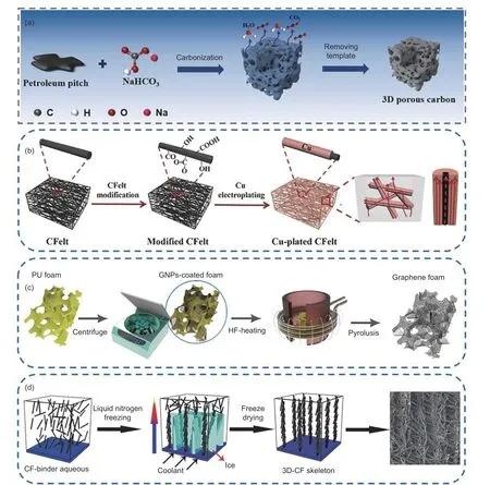
Fig. 9 Some related 3D carbon filler construction methods. (a) Construct 3D porous carbon by adding pore forming agents[85]. Copyright 2022 Elsevier Ltd.(b) 3D Cu film network constructed by carbon felt skeleton[86]. Copyright 2020 Elsevier Ltd. (c) 3D interconnected graphene foam constructed by polyurethane sponge template[87]. Copyright 2019 RSC Pub. (d) 3D vertically arranged carbon fiber skeleton constructed by vertical freezing[88]. Copyright 2020 Elsevier Ltd
3D carbon filler/metal composites are usually prepared by pre-constructing 3D carbon filler skeleton and then composite with metal matrix. The construction methods of 3D carbon filler skeleton have been discussed above. The process of combining the 3D skeleton with the metal matrix into a high-density composite is also critical. Consolidation of composites is mainly achieved using solid-phase and liquidphase methods. High-temperature and high-pressure,hot pressing, and spark plasma sintering (SPS) are the main processes for preparing 3D carbon filler/metal composites by solid-state method. 3D diamond/metal composites are usually prepared by high-temperature and high-pressure due to the ultra-high strength and hardness of diamond[36,74,89-91]. The schematic diagram of high-temperature and high-pressure experimental equipment is shown in Fig. 10[90]. High density and comprehensive properties can be obtained under high pressure which are difficult to achieve under normal pressure. A diamond/Cu composite with thermal conductivity up to 900 W m-1K-1was prepared by high-temperature and high-pressure method.The study indicates that high pressure causes diamond particles to form partially continuous heat conduction channels in the matrix, which improves the thermal conductivity of the composite. The advantages of the high-temperature and high-pressure method include high sample density, short preparation time, and direct bonding between diamond particles.Nevertheless, the technique comes with a few drawbacks such as high cost (special 6-sided top press required) and inability to produce complex shaped parts.Furthermore, the preparation of 3D carbon filler/metal composites using hot pressing and SPS has been widely studied[38,83,92-94]. Hot pressing and SPS can obtain high-density composites at lower sintering temperatures. However, the production costs of hot pressing and SPS are high, and it is difficult to achieve mass production. To retain the integrity of 3D interconnected network during sintering, it is necessary to construct 3D carbon filler with certain strength.
Infiltration method is a typical representative of liquid-phase method for preparing metal matrix composite. Infiltration method used in the fabrication of 3D carbon filler/metal composites mainly includes mechanical pressure infiltration[37,76,95-97]and gas pressure infiltration[5,98-102]. In the study carried out by Liu et al., the interconnected short graphite fiber/Al composites were prepared using an improved 2-step vacuum pressure infiltration technique. As shown in Fig. 11a, the improved 2-step infiltration method effectively preserved the network structure of graphite fibers, resulting in high-density composites with remarkable thermal conductivity[95]. On the other hand,dense 3D diamond network/Al high thermal conductivity composites were obtainedviagas pressure infiltration, as illustrated in Fig. 11b[98]. The findings revealed that low-pressure gas pressure infiltration technique can maintaining the uniformity and integrity of the diamond skeleton within the Al matrix. Additionally, the gas pressure infiltration process established a tightly bonded interface while limiting the formation of interface reaction products. Thus, selecting the appropriate composite process for different 3D carbon filler networks is the key to obtain high thermal conductivity composites.

Fig. 10 Diagram of high-temperature and high-pressure experimental equipment: (a) High-temperature and high-pressure assembly block physical.(b) Diagram of high-temperature and high-pressure assembly block. (c) Diagram of the chamber of high-temperature and high-pressure equipment[90]
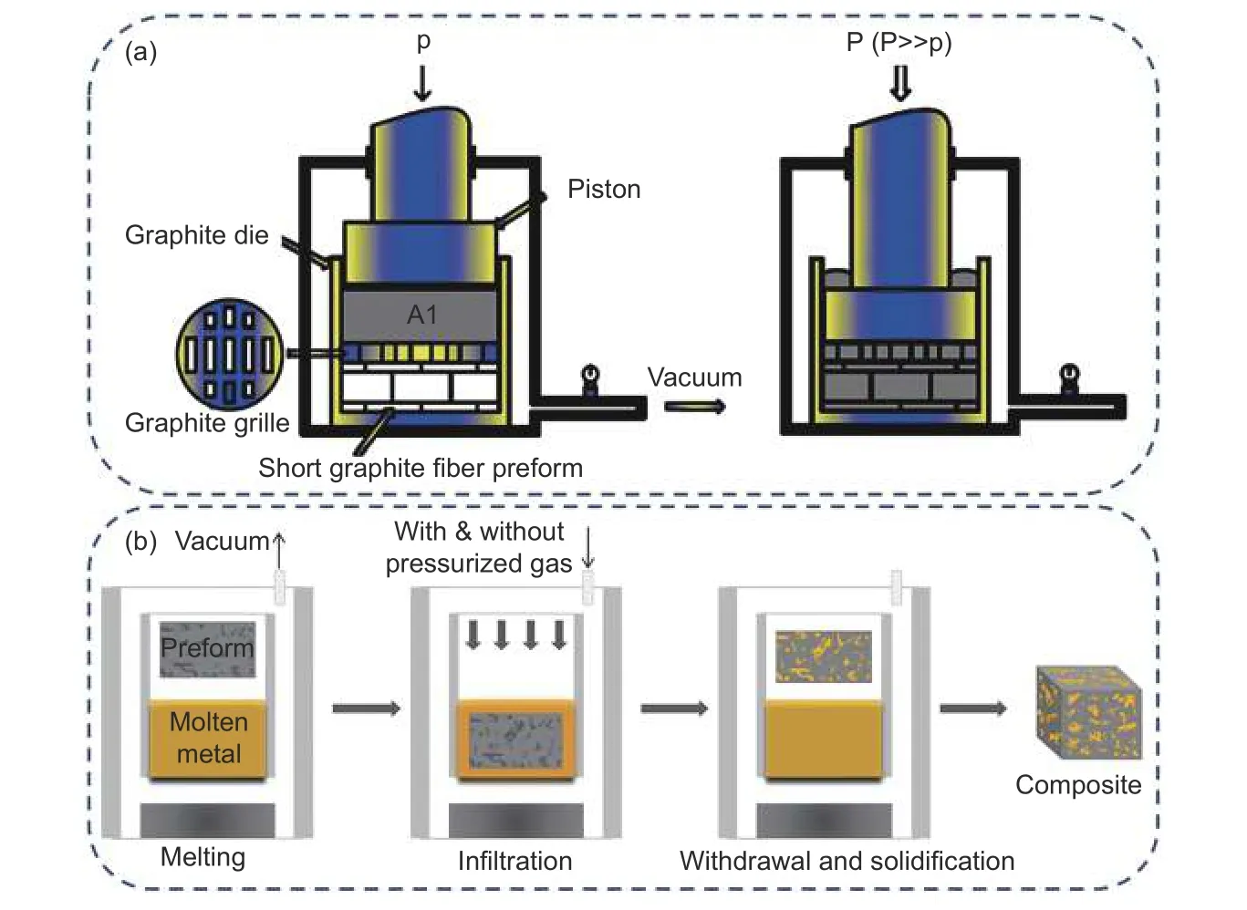
Fig. 11 Schematic diagram of 3D carbon filler/metal composite prepared by infiltration method. (a) Schematic diagram of the two-step vacuum pressure infiltration technique[95]. Copyright 2014 Springer Nature. (b) Schematic diagram of the gas pressure infiltration process[98]
4 Conclusion and outlook
This review focuses on 3D interconnected carbon filler/metal thermal conductivity composites. Cu and Al are the most commonly used matrix materials in metal-based thermal conductivity composites. The high thermal conductivity carbon fillers include micron-scale diamond, carbon fiber and graphite sheets,as well as nanoscale graphene and carbon nanotubes.Although carbon filler/metal composites have high theoretical thermal conductivity, the thermal conductivity of traditional dispersed carbon filler/metal composites is much lower than expected. To overcome this issue, researchers have proposed constructing carbon fillers into 3D network structures to improve the thermal conductivity of composites. Due to the 3D structure being more conducive to heat transfer than traditional dispersed forms, the thermal conductivity potential of carbon fillers in composites can be maximized. The factors affecting the thermal conductivity of 3D fillers reinforced composites include filler content, pore size, filler shape, multiphase filler hybridization, filler-filler interface, filler-matrix interface, and secondary networks. Micro-nano scale 3D filler can be customized by optimizing the process parameters of 3D filler construction method. The multi-scale design of 3D filler can obtain the thermal conductivity composite with better comprehensive performance.The 3D carbon filler constructed by template methods(especially template-directed CVD method) show better connectivity and isotropy. Although there are still some challenges in the development of 3D carbon filler/metal thermal conductive composites, there are many opportunities to improve thermal conductivity while combining other interesting properties. Based on the previous research, potential solutions and future development directions for the existing challenges of 3D carbon filler/metal composite preparation technology are proposed, which are summarized as follows.
(1) The heat source generated by devices in practical application is usually a combination (point heat source or plane heat source). In order to achieve efficient heat dissipation, thermal conductive materials are required to have both high in-plane and throughplane thermal conductivity. The construction of 3D interconnected fillers in the matrix solves the problem of anisotropic fillers being able to only dissipate heat directionally. Especially the isotropic 3D filler constructed through templates, the composites prepared with this 3D filler have excellent thermal conductivity. On the basis of 3D structure, increasing the loading amount of filler and constructing a secondary network may further improve the thermal conductivity of the composites.
(2) Generally, it is a challenge to prepare 3D carbon filler/metal composites with high filler content using the template method. And the high filler content reduces the pore size of the 3D carbon filler skeleton,making it more difficult to fill the metal matrix. Increasing the volume fraction of carbon filler can improve the heat dissipation efficiency and reduce the thermal expansion coefficient and density of carbon filler/metal composite. However, overfilling can significantly reduce the mechanical properties of the composites. Therefore, it is necessary to explore the effect of carbon filler volume fraction on the comprehensive properties of composites. Appropriately increasing the volume fraction of carbon fillers while ensuring highquality 3D filler structures is one of the future research topics. It is necessary to optimize the existing process parameters or develop a new preparation process.
(3) The thermal conductivity of 3D carbon filler/metal composites is mainly affected by the interface thermal resistance. More efficient interfacial heat transfer can be realized by optimizing the structure of filler interface. However, most existing thermal conductivity prediction models are based on simple spherical fillers, which have significant errors with the actual data of composites. For constructed 3D filler structures, the development of comprehensive multiscale analytical models will help to understand the structure-performance relationship. This will greatly shorten the development cycle and reduce the cost of the composites.
(4) In the development of metal-based thermal conductivity composites, it is essential to not only consider the thermal conductivity value but also the thermal expansion coefficient, thermal stability, and long-term performance, among other factors.Moreover, thermal conductivity composites with multifunctional properties are more attractive, so it is necessary to actively explore their application in complex application scenarios. Integrating more functions into thermal conductive composites, such as electromagnetic interference shielding, corrosion resistance,and high temperature resistance, will expand their potential applications and enable them to be used in a wider range of fields.
(5) Currently, most 3D carbon filler/metal composites are prepared on laboratory scale. The lack of large-scale production is one of the main factors limiting the practical application of 3D carbon filler/metal composites. The existing foam templates and template-directed CVD are promising strategies for largescale production of high-performance thermal conductivity composites. However, cost reduction and improved production efficiency are key to successful implementation. Furthermore, the versatility and commercialization of high-performance thermal conductivity composites will increase their diverse applications in the field of thermal management.
Acknowledgements
This work was financially supported by the National Natural Science Foundation of China(51274040).
- 新型炭材料的其它文章
- Large-scale synthesis of 3D ordered microporous carbon at low temperature using cobalt ions exchanged zeolite Y as a template
- Highly efficient Co—N—C electrocatalysts with a porous structure for the oxygen reduction reaction
- Reversible surface modification of PAN-based carbon fibers by a ferrocene-based surfactant
- Development of biochar electrode materials for capacitive deionization: preparation, performance, regeneration and other challenges
- Synthesis and electrochemical properties of nano-Si/C composite anodes for lithium-ion batteries
- Factors that influence the performance of hydrogen detectors based on single-wall carbon nanotubes

