Effect of multifunction cavitation using phosphoric acid on fatigue and surface properties of AZ31 magnesium alloy
Shunt Mtsuok ,Fumihiro Kto ,Toshihiko Yoshimur ,Mstk Ijiri ,Shoihi Kikuhi
aGraduate School of Integrated Science and Technology,Shizuoka University,3-5-1 Johoku,Naka-ku,Hamamatsu,Shizuoka,432-8561,Japan
b Department of Mechanical Engineering,Sanyo-Onoda City University,1-1-1 Daigaku-Dori,Sanyo-Onoda,Yamaguchi 756-0884,Japan
c Tokyo Metropolitan University,1-1 Minami-Osawa,Hachioji,Tokyo 192-0397,Japan
d Department of Mechanical Engineering,Faculty of Engineering,Shizuoka University,3-5-1 Johoku,Naka-ku,Hamamatsu-shi,Shizuoka 432-8561,Japan
Abstract Magnesium alloy is attractive for lightweight construction but often suffers from poor corrosion resistance and low strength.Cavitation processing with chemicals,i.e.,multifunction cavitation (MFC),was introduced to form a high-corrosion film and improve the fatigue properties of an AZ31 magnesium alloy.Surface analysis and plane bending fatigue tests were conducted for the MFC-treated magnesium alloy at a stress ratio,R,of-1.The mechanical action of cavitation bubbles improved the fatigue life of magnesium alloys due to increasing the surface hardness and generating compressive residual stress.However,the combined mechanical and electrochemical action during MFC formed pits on the surface.These pits were large enough to easily nucleate an initial fatigue crack.In addition,the magnesium alloys without pit formation,for which a coating process using phosphoric acid was conducted after MFC using water,showed superior fatigue properties.
Keywords: Magnesium alloy;Multifunction cavitation;Surface modification;Fatigue;Residual stress.
1.Introduction
In order to realize a decarbonized society,electric vehicles and hydrogen vehicles are gradually becoming popular.Since the body of such vehicles is approximately 15–20%[1] heavier than that for a gasoline car,methods are being developed to reduce the weight of the parts used in the car body.In order to reduce the weight,it is necessary to use light metals having high strength on behalf of steels because most automobile components are made by metallic materials.Therefore,surface processing technology is required to suppress the damage,such as wear,oxidation,fatigue failure and corrosion,occurred at the surface.Furthermore,in recent years,there has been a demand for environmentally friendly technology that does not generate solid or liquid waste in terms of sustainable development goals (SDGs).
In particular,magnesium (Mg) alloy has the lowest density among practical metals and has excellent specific strength and specific stiffness.In addition,Mg exists abundantly on the Earth and is attracting attention as a new structural material along with carbon-fiber-reinforced composite materials[2].However,since Mg is a base metal,it has poor corrosion resistance.In addition,the strength of Mg alloys is low.In particular,the fatigue properties of Mg alloys need to be investigated,because most machine and structural components used in engineering fields are prone to fatigue fracture at the surface.Therefore,it is necessary to consider both improvement of the corrosion resistance and the unique fatigue fracture mechanism associated with its hexagonal close-packed(hcp)structure for the purpose of using Mg alloys in strengthening members [3–8].Thus,surface treatments are effective means of improving the mechanical and chemical properties of lightweight materials,including the Mg alloys highlighted in the present study[9–11]because the fatigue failure and corrosion generally occur at the surface.Uematsu et al.[10] reported that the corrosion fatigue strength of a wrought magnesium alloy AZ80A was improved by multilayer diamond-like carbon coatings.Chemical conversion treatment[12,13],polymer coating [14,15],silane coating [16,17],and atmosphericpressure plasma jets[18]are used to improve the corrosion resistance of Mg alloys.Among these surface treatments,chemical conversion treatment has advantages such as low cost and easy operation.However,the use of chromate-or vanadatebased coatings is discouraged due to environmental pollution problems.
Thus,we focused on the cavitation phenomenon that occurs in water as an environmentally friendly processing technology.There are two ways to generate cavitation bubbles.Ultrasonic cavitation [19] is a method that uses the shock wave generated by bursting cavitation bubbles that change due to the difference in pressure caused by ultrasonic vibration.The inside of the cavitation bubbles generated by this method has a temperature of about 5000 K,and the temperature of the shell is estimated to be about 1800 K [20].On the other hand,water jet peening [21,22] generates a strong shear force by injecting high-pressure water into water,resulting in strong eddies and turbulence.The pressure in that region drops to the level of the vapor pressure and cavitation bubbles are generated.When a cavitation bubble moves downstream of the jet,the pressure recovers to normal levels and the cavitation bubble rapidly contracts.This phenomenon is referred to as the collapse of the cavitation bubble and generates a very large shock wave of approximately 1 GPa.
Multifunction cavitation (MFC) [23–25] is a technology that combines these two actions.Multifunction cavitation repeats isothermal expansion and adiabatic compression using ultrasonic irradiation in the process of moving downstream of the jet after cavitation bubbles (similar to the action of WJP)are generated,and grow into bubbles with high temperature and high pressure.When these cavitation bubbles collapse,they generate a shock wave with a temperature of several thousand kelvins and a high pressure of several gigapascals that can modify solid surfaces.Furthermore,the MFC process has been improved and an energy-intensive multifunction cavitation (EI-MFC) device [26] that integrates ultrasonic waves and a water jet nozzle,as well as a magnetic energy-intensive multifunction cavitation (MEI-MFC) device [27] that incorporates magnetism into cavitation bubbles,has been reported.Among these devices,there are mechanochemical multifunctional cavitation treatments that improve the corrosion resistance of materials such as Mg alloys [28–30] and steels[31,32]due to the formation of surface modified layers.In addition,the authors have developed a MFC processing device with a mechanism that moves a nozzle capable of processing a wide coverage [33],and the MFC treatment induces compressive residual stress on the surfaces of aluminum alloys[34] and steels [35,36],improving the hardness and fracture toughness;therefore,the MFC process would be an effective approach for improving the chemical and mechanical prop erties of Mg alloys in the engineering field.However,the fatigue fracture mechanisms for Mg alloys treated with MFC were not discussed in detail.
In the present study,the surface microstructure of the MFC-treated magnesium alloys was characterized on the basis of the previous studies [28–30],and its effects on the plane bending fatigue properties were mainly investigated.The mechanisms for fatigue crack initiation and propagation in Mg alloys treated with MFC was experimentally investigated on the basis of fractography.In addition,the effect of combined mechanical and chemical action during MFC on the pit formation was elucidated.
2.Experimental procedures
2.1. Materials
The material used in the present study was an extruded AZ31 magnesium alloy plate.The chemical composition (in mass%) of the alloy is shown in Table 1.The material has a texture in which thec-axis of the crystals is normal to the specimen surface.The average grain size is 52 μm [5],and the tensile and compressive yield strengths are 286 and 79 MPa,respectively.This material has a fatigue strength ofσw=100 MPa atN=107cycles in plane bending fatigue tests under the conditions of a stress ratio,R,of-1,(whereRis the ratio of the minimum to maximum bending moment during one fatigue loading cycle) at a frequency of 30 Hz [5].This material has a Vickers hardness of 64.1 ± 5.3 HV,as measured for a polished surface with an indentation force of 0.098 N and a load holding time of 10 s (n=30) [18].

Table 1Chemical composition of AZ31 magnesium alloy (mass%).
2.2. Specimens and multifunction cavitation (MFC)
The geometry and dimensions of the fatigue test specimens and schematics of the equipment for surface treatment by cavitation processing are shown in Fig.1.The specimen shown in Fig.1(a) was cut by wire electric discharge machining from an extruded plate so that the longitudinal direction of every specimen coincided with the direction of extrusion.Thus,the texture orientation of AZ31 alloy has no effects on the surface morphology and fatigue properties of MFC treated specimens in this study.After that,surface processing of these specimens was performed using MFC.Fig.1(b) through (d)shows a schematic diagram of cavitation processing.In MFC processing,an ultrasonic transmitter is installed to propagate the waves in a direction perpendicular to the orientation of the WJ nozzle,and ultrasonic waves are applied to the highpressure water jet used to process the specimen surface.In the present study,fixed-point injection of the WJ nozzle was used because,based on a previous study,only the part of the specimen subjected to the maximum bending stress was targeted for surface strengthening[36].In addition to these techniques,to form a phosphoric acid compound film on the surface of the Mg alloy,processing was carried out while introducing a liquid comprising a mixture of 200 mL of water and 20 mL of phosphoric acid into the conduit of the WJ nozzle,as shown in Fig.1(b).The suction force of the conduit during processing was-7.17 KPa (absolute pressure).The total processing time was 5 min for all processes,and the concentration of phosphoric acid in the liquid after processing was 8.87 ×10⁻⁴mass%,which suggests that solid or liquid waste are not generated.In the present paper,processing of the surface with dilute phosphoric acid added during MFC processing is referred to as the MFC-WP technique (Fig.1(b)).For comparison,MFC processing using only water is referred to as the MFC-WW technique(Fig.1(c)),and processing with only ultrasonic irradiation in dilute phosphoric acid is referred to as the UC technique(Fig.1(d)).The discharge pressure of the pump was approximately 35 MPa.The nozzle diameter was 0.8 mm,and the distance between the nozzle and the specimen surface was 65 mm [30,37].Processing was performed in a tank made from austenitic stainless steel with dimensions of 41 cm × 44 cm × 60 cm.The output of the ultrasonic transducer (WD-1200-28T,Honda Electronics Co.,Ltd.) was 800 W [38],and the nominal drive frequency was 28 kHz.The processing time was 5 min.The water temperature was 12.7 °C,and the pH of the high-pressure water was 6.6 to 6.9.

Fig.1.Schematic diagrams of cavitation treatment: (a) specimen configuration for the plane bending fatigue test,(b) MFC-WP treatment system,(c) MFC-WW treatment system,and (d) UC treatment system.
2.3. Testing
A computer-controlled electrodynamic testing machine with an in-situ crack observation system was used for the fatigue experiments.Fig.2 shows the experimental setup for the plane bending fatigue test.Since the machine generated an axial force,an in-plane cyclic bending moment was applied to the specimen through a loading device with an arm length of 20 mm.The tests were conducted with a stress ratio ofR=-1 and a frequency of 30 Hz.To determine the mechanisms for fatigue crack initiation and propagation in the Mg alloy,optical microscopy was conducted on the surfaces of some specimens under fatigue testing.The optical microscope featured a lens barrel (CM-10L,Nikon),an objective lens (M Plan Apo SL20x,Mitsutoyo),and an image sensor(UI-3180CP-C-HQ R2.1,IDS) [39].The numerical aperture of the objective lens was 0.28.The diffraction limit of the optical microscope was smaller than the expected crack lengths.
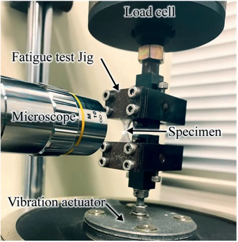
Fig.2.Photograph of in-situ fatigue crack observation system.
The specimen surface and fracture surface were observed by scanning electron microscopy (SEM) at an acceleration voltage of 15 kV.In addition,the surface chemical composition was analyzed by electron probe microanalysis (EPMA)at an acceleration voltage of 15 kV to characterize the surface modified layer.The hardness on the treated surfaces was measured using a micro-Vickers hardness tester with an indentation force of 0.098 N and a load holding time of 10 s.The hardness distribution of the MFC-WP series was also measured.The specimen was embedded in resin and was polished before the hardness tests.The residual stress was measured at the surface of the Mg alloy using a portable X-ray device(type μ-360 s,Pulstec Industrial Co.,Ltd.).Measurements based on the cosαmethod were performed in the longitudinal direction for the fatigue-test specimen using the Co-Kαline generated at 30 kV and 1.5 mA.With consideration of the target material,the diffraction planeh,k,l(2 1 2),the corresponding diffraction angle of 2θ=133.48°,and an Xray incidence angle of 25° were selected,and measurements were performed using multi-angle oscillation.The residual stress distribution of the MFC-WP series was also measured.
3.Results
3.1. Effect of MFC processing on surface morphology of AZ31 Mg alloy
The surface residual stresses determined using X-ray diffraction are shown in Fig.3(a).It can be seen that the residual stress generated by polishing of the untreated series specimen was-48 MPa.In contrast,a compressive residual stress of approximately 130 MPa,which was higher than that of the untreated series,was measured at the surfaces of the MFC series specimens,indicating that the compressive residual stress was generated by MFC processing.The compressive residual stress for the MFC-WW and the MFC-WP series showed approximately the same value.Fig.3(b) shows the residual stress distribution of the MFC-WP series at crosssectional depths.The dotted line in this figure indicates the residual stress measured at the top surface of the untreated specimen for comparison.The values of compressive residual stress of the MFC-WP series measured from the top surface to 60 mm in depth were higher than those measured inside the specimen similar to the value of the untreated specimen.
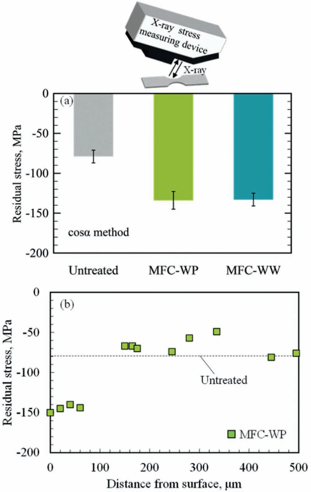
Fig.3.(a) Residual stress at top surface of AZ31 magnesium alloy treated with MFC and(b)distribution of residual stress of MFC-WP series specimen.
Fig.4(a)shows the Vickers hardness measured at the specimen surface.The surface hardness for the MFC-treated specimen is much greater than that for the untreated specimen(64.1 ± 0.3 HV),indicating that the surface was hardened by the MFC processing.This was attributed to work-hardening by the MFC.In addition,for the treated specimens(the MFCWW and MFC-WP specimens),the surface Vickers hardnesses are 106.0 ± 18.3 HV and 92.5 ± 7.2 HV,respectively.It is considered that this difference can be attributed to the modified layer formed on the surface by processing using chemicals.Fig.4(b) shows the Vickers hardness distribution of the MFC-WP series at cross-sectional depths.The dotted line in this figure indicates the hardness of the untreated specimen for comparison.The thickness of the hardened layer in the MFC-WP series was approximately 60 μm.
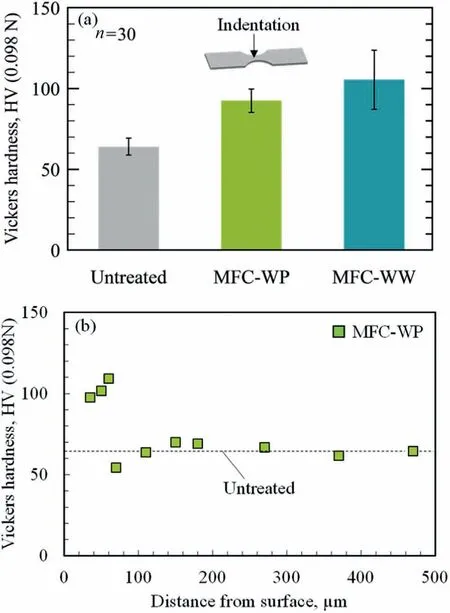
Fig.4.(a) Vickers hardness measured at top surface of AZ31 magnesium alloy treated with MFC and (b) distribution of Vickers hardness of MFC-WP series specimen.
To investigate the microstructure of the surface modified layer formed on magnesium alloys treated with MFC processing,the elemental intensity distribution was analyzed for the MFC-WW and MFC-WP series by EPMA.Fig.5 shows the EPMA mapping results for Mg,O,and P,and SEM micrographs for specimen surface.P was not detected in the untreated specimen (Fig.5(a)) or the MFC-WW series specimens (Fig.5(c)),whereas the MFC-WP-treated specimen(Fig.5(b)) showed a high P intensity.The results confirm that MFC-WP processing formed a phosphate film on the magnesium alloy surface.The film with P and O elements formed by MFC-WP has high potential to improve corrosion resistance by protecting underlying material from a corrosive environment [40,41].The authors reported that MFC-WP treatment formed a film on the AZ31 alloy surface that contained phosphate compounds,including oxides,hydroxides,and carbides as determined by the GD-OES analysis[28,29],and improved the corrosion resistance by the immersion tests [30].Nakamura et al.[42] reported that Mg(OH)2was formed due to the dissolution of Mg and generation of H2when Mg was immersed into the acid solution or neutral solution,and then phosphate Mg3(PO4)2was formed.Therefore,we can identify the surface modified layer related to the corrosion resistance on the basis of our previous studies [28–30] and the reference[42].In addition,the MFC-WW-treated specimen has a higher O signal intensity than the untreated specimen.These results confirm that the surface modified layer formed by MFC-WP processing is different from that formed by MFC-WW processing.Consequently,MFC formed a surface modified layer having high hardness and compressive residual stress.
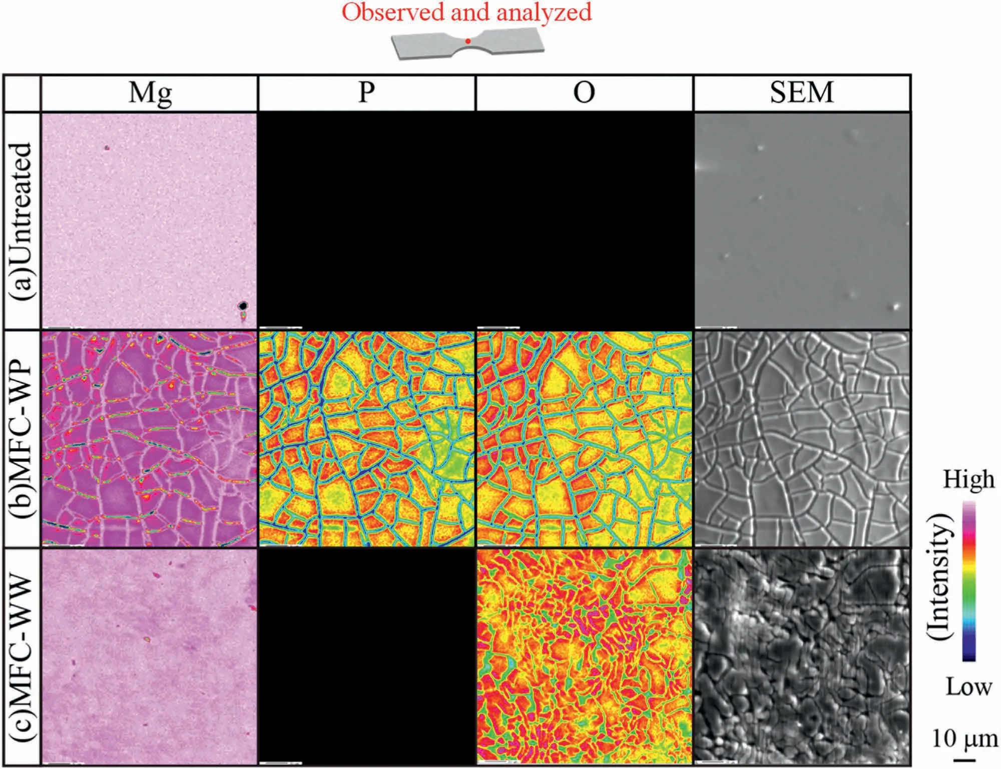
Fig.5.SEM images and elemental maps obtained by EPMA for (a) untreated,(b) MFC-WP,and (c) MFC-WW series specimens.
3.2. Effect of MFC processing on plane bending fatigue properties of AZ31 Mg alloy
In order to investigate the effect of the MFC process on the fatigue properties,plane bending fatigue tests were conducted.Fig.6 shows the results of plane bending fatigue tests for Mg alloys treated with MFC.The symbols with an arrow represent a run-out specimen without failure,and the data for the untreated specimen are also shown for comparison [5].It can be seen thatNffor the entire series increases with decreasingσa.Multifunction cavitation increased the fatigue life of Mg alloys in comparison to the untreated specimen.This is because MFC increased the surface hardness and generated compressive residual stress,as shown in Figs.3 and 4.However,the fatigue life for the MFC-WP series was shorter than that for the MFC-WW series at high stress level.This implies that the fatigue lives of the MFC series depend on the surface modified layer,and P was detected only on the surface of the MFC-WP series specimens,as shown in Fig.5.Furthermore,the fatigue strength at 107cycles for the MFC series specimen was approximately the same as that for the untreated specimen.
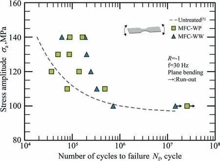
Fig.6.Results of plane bending fatigue tests for AZ31 magnesium alloy.
The fracture surfaces of the failed specimens were observed by SEM to investigate the fracture mechanism for Mg alloys treated with MFC.Fig.7 shows an SEM fractograph for each specimen near the crack initiation site.The untreated series and the MFC-WW series failed as a result of surface-initiated fracture (Fig.7(a) and (c)).Fig.7(b) shows an SEM fractograph of the MFC-WP series,and Fig.7(d)shows a high-magnification view of the crack nucleation site for the MFC-WP series.A pit produced by cavitation bubbles in phosphoric acid can be seen at the crack initiation site for the MFC-WP series [28,30],which suggests that pit influence the fatigue life.On the other hand,no pits were observed on the surfaces of the untreated and MFC-WW series specimens.In general,fatigue life is essentially divided into two regions: crack nucleation life and crack propagation life.Crack nucleation is known to be sensitive to the surface condition.Therefore,pits significantly influence the fatigue nucleation life [3,43].However,the fatigue strength at 107cycles for the MFC-WP series specimen was same as that for the MFC-WW series specimen.

Fig.7.SEM images of fracture surfaces of (a) untreated,(b) MFC-WP,(c) MFC-WW specimens,and (d) enlarged image of MFC-WP series tested at σa=140 MPa.
Consequently,multifunction cavitation treatment with chemicals formed pits,which results in the reduction of the fatigue life of Mg alloys,but did not reduce the fatigue strength at 107cycles due to the formation of a surface modified layer having a high hardness and compressive residual stress.
4.Discussion
4.1. Mechanism of fatigue crack initiation in MFC-treated Mg alloys
In order to elucidate the influence of surface pits on fatigue crack initiation,initiation and propagation of small fatigue cracks were observed for the MFC-WP series during plane bending fatigue tests using an optical microscope.Fig.8(a) through (e) shows optical micrographs,and Fig.8(f)shows an SEM micrograph of the MFC-WP surface tested atσa=140 MPa.A pit induced by the MFC-WP treatment was observed on the surface.Fig.8(a) and (b) revealed that there were no fatigue cracks in this series at 0 cycles or 1.05 × 10⁵cycles.Then,a single fatigue crack appeared abruptly from the root of the pit induced by the MFC-WP treatment after 1.15 × 10⁵cycles (Fig.8(c)) and gradually propagated with increasing numbers of cycles (Fig.8(d) and(e)).A high-magnification SEM micrograph of the specimen surface after the fatigue test is shown in Fig.8(f).A fatigue crack propagated through the surface pit,and the surface modified layer formed by the MFC-WP treatment was locally peeled.

Fig.8.Optical micrographs of MFC-WP series obtained at (a) N=0,(b) N=1.05 × 10⁵,(c) N=1.15 × 10⁵,(d) N=1.55 × 10⁵,and (e) N=1.63 ×10⁵ cycles,and (f) SEM image obtained at N=1.63 × 10⁵ cycles tests at σa=140 MPa.
The effect of the MFC-WP treatment on fatigue crack initiation and propagation was examined quantitatively.Fig.9 plots the surface crack length against the number of cycles for Mg alloys treated with MFC tested atσa=140 MPa.The data for the untreated specimen are also shown for comparison [5].MFC increased the fatigue crack initiation life for Mg alloys in comparison to the untreated specimen.This is because MFC increased the surface hardness,as shown in Fig.4.Furthermore,MFC increased the fatigue crack propagation life for Mg alloys in comparison to the untreated specimen.This is because MFC generated compressive residual stress,as shown in Fig.3.These results indicate that the improvement in the fatigue life for Mg alloys by MFC was attributed to peening effect,i.e.,deceleration of the surface crack propagation rate caused by the compressive residual stress,and the increase in the surface crack initiation resistance caused by the surface hardness.
Fig.9 also shows that the fatigue crack initiation life for the MFC-WP series is slightly shorter than that for the MFCWW series.This implies that pits induced by MFC-WP have a harmful effect on fatigue crack initiation in Mg alloys.In order to clarify the effect of surface morphology on the fatigue properties,the topography of the magnesium alloys was characterized by SEM.Fig.10 shows a height profile of the specimen surface treated with (a) MFC-WP and (b) MFCWW,and (c) a cross-sectional profile for a specimen treated with MFC.No surface pits were observed on the surface treated with MFC-WW (Fig.10(b)).In contrast,the maximum distance between the highest and lowest points of the pit formed in MFC-WP was 23.7 μm,whereas the maximum distance between the highest and lowest points on the surface for MFC-WW was 1.4 μm.The pit formed in the MFC-WP series was very large compared to the surface topography of the MFC-WW series.Thus,the fatigue crack initiation life for the MFC-WW series was slightly longer than that for the MFC-WP series because fatigue crack initiation from surface pits was suppressed.

Fig.10.Surface topography of (a) MFC-WP series and (b) MFC-WW series specimens,and (c) cross-sectional profiles of specimens treated with MFC.
Consequently,the fatigue properties of Mg alloys were improved by the MFC-WP treatment due to the peening effect,but harmful effects on fatigue properties were observed due to the surface pits.
4.2. Improvement of fatigue properties of Mg alloys by processing combined with MFC-WW and UC
Fatigue cracks were initiated from surface pits formed by MFC with chemicals,as described in the previous sections.In this section,in order to elucidate the mechanism of pit formation and suppress pit formation as a result of the MFC treatment,UC treatment was performed for the MFC-WWtreated Mg alloys.
In the water immersion test [30] of Mg alloy using phosphoric acid,the shape of the film formed on the surface differs depending on the concentration of phosphoric acid,and the thickness of the film is not uniform.Since this film is formed by a dissolution reaction on the Mg alloy surface and a pH fluctuation near the interface,segregation is likely to occur [42,44].Therefore,even if phosphoric acid is used in the MFC treatment,the chemical reaction is significantly accelerated at the same time that the cavitation bubble collapses,and the depth of the pit is considered to be large.The cause is thought to be the generation of high pressure when the cavitation bubble collapses.Therefore,in order to reduce the chemical reaction,the WW+UC series was produced using no chemicals in the MFC treatment,and only water was used (MFC-WW treatment),followed by surface treatment by ultrasonic cavitation using phosphoric acid (UC treatment) to produce the WW+UC series (Fig.11(b)).The phosphoric acid concentration and the ultrasonic cavitation conditions were the same as those for the MFC+WP treatment.Fig.11(a) shows EPMA mapping results for O and P for the WW+UC series,together with SEM micrographs.Compared with the MFC-WP series,in which peening effect and film formation simultaneously occurred (Fig.5(b)),the WW+UC-treated specimen had approximately the same P and O intensities.The results confirm that WW+UC processing formed a phosphate film on the magnesium alloy surface.Film formation was confirmed on the surface after immersion in phosphoric acid.However,the film thickness was negligible [28].
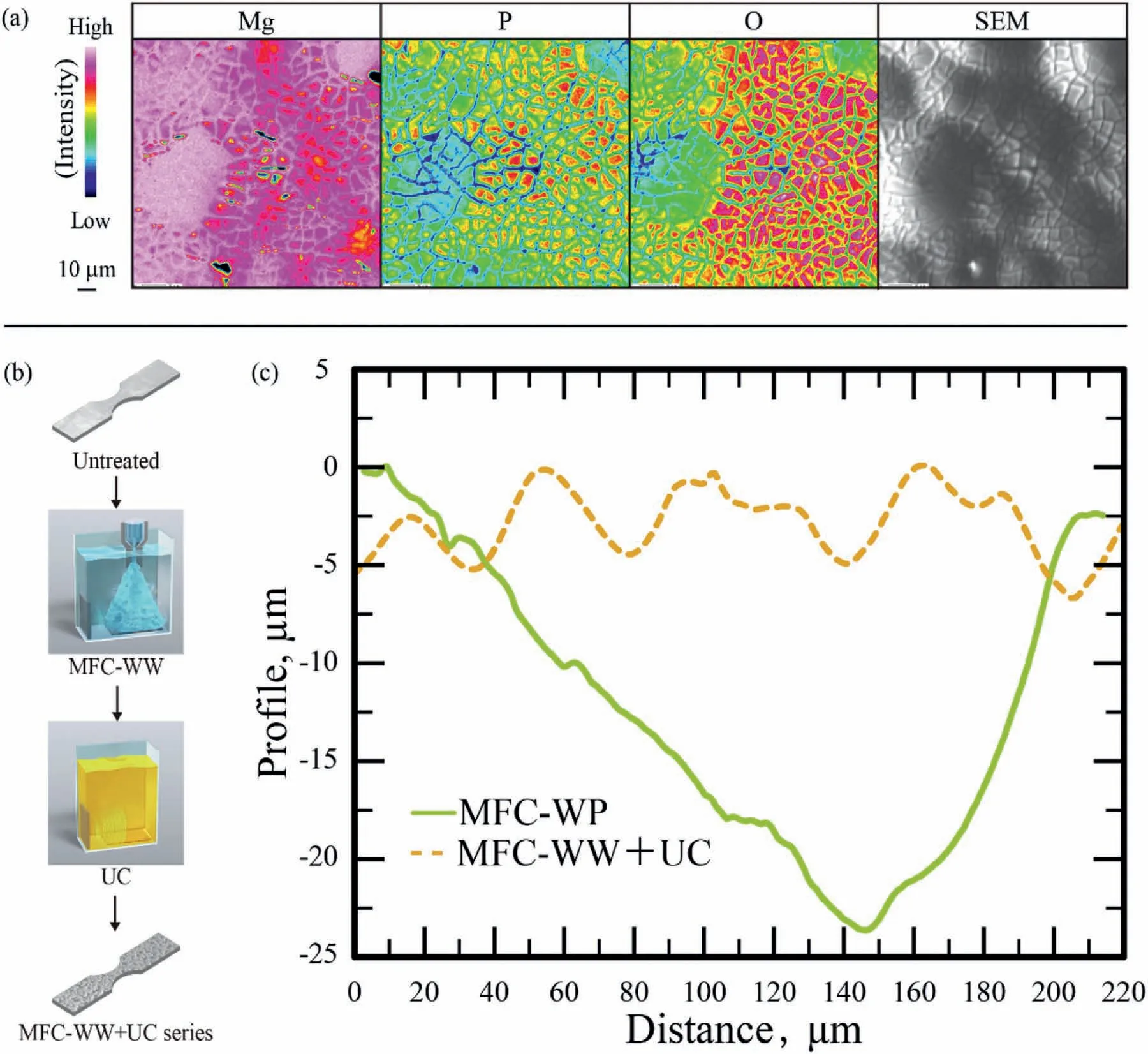
Fig.11.(a) SEM image and elemental maps obtained by EPMA for WW+UC surface,(b) schematic illustrations showing specimen preparation procedure,and (c) cross-sectional profiles of MFC-WP and MFC-WW+UC series specimens.
Fig.11(c) shows a cross-sectional profile of specimens treated with MFC-WW+UC and MFC-WP.The maximum distance between the highest and lowest points of the pit formed by MFC-WP was 23.7 μm,whereas that for MFCWW+UC was 6.8 μm.The undulating topography of the MFC-WW+UC series was very small compared to the pits formed in the MFC-WP series.These results indicate that formation of pits in the MFC-WP series is due to the combined effects of the high-temperature,high-pressure cavitation bubbles and cavitation jets.
Plane bending fatigue tests were also conducted for the MFC-WW+UC series.The results are plotted asS–Ndiagrams in Fig.12 for the MFC-WW+UC series,and the results for the MFC-WP series are also shown for comparison.It can be seen thatNffor the entire series increases with decreasingσa.The fatigue life for the MFC-WW+UC series was approximately the same as that for the MFC-WP series.On the other hand,the MFC-WW+UC series had a higher fatigue strength at 107cycles than the MFC-WP series.This is attributed to the suppression of surface pit formation.Furthermore,compressive residual stress (-111 MPa),which was slightly lower than that of the MFC-WW series as shown in Fig.3(a),was generated.Thus,UC treatment did not significantly release residual stress generated by the MFC-WW process because a temperature rise on the specimen surface did not occur during the UC treatment due to the lower pressure and temperature of bubbles rather than the MFC processing.In addition,the surface hardness was increased (117.6 ±37.8 HV),which showed approximately the same as the MFCWW series as shown in Fig.4(a),due to the combined effect of UC and MFC-WW treatments.These results indicate that the MFC-WW+UC series exhibited superior fatigue properties compared to the other treated specimens because peening effect occurred while pit formation was suppressed when the peening and coating processes were separated.
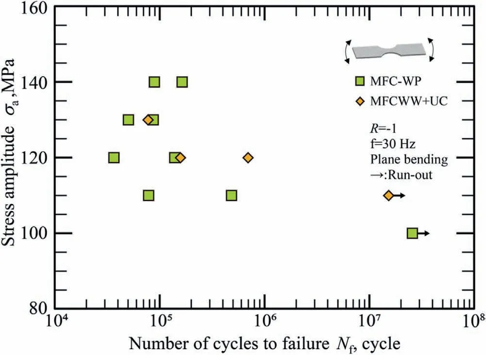
Fig.12.Results of plane bending fatigue tests for AZ31 magnesium alloy.
Thus,we separated the effects of surface pits and peening on the fatigue properties of Mg alloys treated with MFC using chemicals.Furthermore,we achieved both film formation and improvement of the fatigue properties by combining UC and MFC treatments.
5.Conclusion
Multifunction cavitation processing with chemicals was introduced to form a highly corrosion-resistant film and improve the fatigue properties of AZ31 magnesium alloy.The surface microstructural changes for the MFC-treated specimen were characterized,and the effect on the plane bending fatigue properties were examined.The main conclusions of the present study are as follows:
1.MFC processing increases the fatigue life for magnesium alloys due to the peening effect,deceleration of the crack growth rate due to generation compressive residual stress,and an increase in the fatigue crack initiation life by an increase in surface hardness.
2.MFC processing with phosphoric acid forms surface pits on magnesium alloys.These pits are large enough to easily nucleate fatigue cracks.
3.Pit formation is attributed to the combined effects of mechanical action and electrochemical action of film formation during MFC processing with phosphoric acid.
4.Magnesium alloys treated with MFC using only water and only ultrasonic irradiation in a phosphoric acid solution exhibit superior fatigue properties.This is because peening effect occurs while pit formation is suppressed when the peening and coating processes are separated.
Declaration of competing interest
The authors declare that they have no known competing financial interests or personal relationships that could have appeared to influence the work reported in this paper.
 Journal of Magnesium and Alloys2023年6期
- Journal of Magnesium and Alloys的其它文章
- Ameliorating the re/dehydrogenation behaviour of MgH2 by zinc titanate addition
- Inhibiting effect of I-phase formation on the plastic instability of the duplex structured Mg-8Li-6Zn-1.2Y (in wt.%) alloy
- PEO coating on Mg-Ag alloy: The incorporation and release of Ag species
- Underlying mechanisms of variation in yield asymmetry and strain hardening behavior of extruded pure Mg with Gd addition
- Edge crack damage analysis of AZ31 magnesium alloy hot-rolled plate improved by vertical roll pre-rolling
- High sintering and dielectric performance: The improved (Mg,Zn)3B2O6 ceramics with the help of the DFT calculation
