Pattern reconfigurable antenna array for 5.8 GHz WBAN applications*
Lingsheng YANG ,Bin WANG ,Yajie LI
1School of Electronics &Information Engineering, Nanjing University of Information Science &Technology, Nanjing 210044, China
2Zhongda Hospital Southeast University, Nanjing 210009, China
A pattern reconfigurable antenna array for 5.8 GHz wireless body area network (WBAN) applications is proposed in this paper.The antenna array consists of a radiation component and a controller component.The radiation component comprises four planar F-shaped antennas,which are located on the four corners of the upper layer and are rotated 90° anticlockwise from each other.The controller component is located in the lower layer and includes a four-port controllable network.An omnidirectional radiation pattern tangent to the human body surface and a directional radiation pattern normal to the human body surface can be obtained by controlling the PIN diodes,which are integrated in this controllable network.Measurements of impedance bandwidth,radiation pattern,and gain are performed when the array is mounted on the human body or forearm phantom,and the results agree with the simulation.Specific absorption rate (SAR) values for both radiation modes,and beam switch ability are also simulated to ensure the practicability of this array.
1 Introduction
WBAN has drawn growing attention from a wide variety of applications,such as wireless communications,medical care,health monitoring,physical training,and military applications (Lee et al.,2017;Wong et al.,2017;Ramaswamy and Gandhi,2022).As the most critical component of WBAN devices,the antenna should be compact,easy to fabricate,robust to the influence of the human body,have a minimal SAR,and be low in cost (Wang MJ et al.,2018;Gökdemir et al.,2022).Even if all these requirements are met,when the antenna is mounted above the dynamic human body,the environment becomes so complex that it is difficult to guarantee low power and secure wireless communication (Cihangir et al.,2018;Yaghoubi et al.,2022).
For WBAN devices,when creeping waves that propagate around the body surface (such as on-body communications between wearable devices) are the main component of all received waves,an antenna with an omnidirectional or monopole-like radiation pattern is suitable.When waves normal to the body surface (such as off-body communications between the communication node and the wearable device) are dominant,an antenna with a directional or patch-antenna-like radiation pattern is preferred (Alves et al.,2011;Shan and Yan,2020).Antennas with pattern diversity,especially antennas that can switch between omnidirectional and directional radiation patterns,can adapt to different application scenarios,and have gained a lot of interest (Kim et al.,2012;Lin et al.,2017;Wang Y et al.,2017).
Scholars worldwide have conducted extensive research around WBAN antennas with radiation pattern diversity (Kim et al.,2012;Yan and Vandenbosch,2016a;Lin et al.,2017).In Kim et al.(2012),by changing the state of two PIN diodes,the power divider provides in-phase and out-of-phase excitation to two branched radiators.Normal and side-direction radiation patterns are realized accordingly.A three-port-fed antenna with tripolarization diversity for wearable communications was proposed in Yao et al.(2012) and Yan and Vandenbosch (2016b).The omnidirectional radiation pattern is generated when an inductively loaded patch antenna is fed in the center,while orthogonal broadside patterns are obtained when a microstrip annular ring antenna is excited by the other two ports separately.In Yan and Vandenbosch (2016a),by reconfiguring the dispersion curve of the inductor-loaded transmission line,the antenna can be switched between the +1 mode or the 0th-order mode,and an omnidirectional or broadside radiation pattern can be achieved,respectively.In Tong et al.(2018),the states of the PIN diodes determine whether the circular patch is connected to the ground,and two working modes are realized accordingly.
This paper describes a four-element antenna array with pattern-diversity performance,designed for 5.8 GHz industrial scientific medical (ISM) band WBAN operations.By changing the working states of the PIN diodes located in the controllable network,two types of radiation patterns can be realized: omnidirectional radiation,which is tangent to the human body surface,and directional radiation,which is normal to the human body surface.Next,the power transmission efficiency method for designing the directional mode is further extended to achieve beam switch ability performance.This paper covers the parameter study of the antenna element and the working principle of the pattern reconfigurable array.Simulation and measurement results and further development of the antenna array-like switchable pattern properties are also presented.
2 Pattern reconfigurable antenna array design
2.1 Four-element antenna array structure
Fig.1 shows the geometry of the proposed antenna array.The antenna array consists of a radiation component and a controller component,which are located in different layers of an FR4 double-layered substrate with relative permittivityεr=4.4,loss tangent tanδ=0.02,and dimensions 30 mm×30 mm×3 mm (layer 1:2 mm;layer 2: 1 mm).The radiation component includes four planar F-shaped antennas,which are located on the top of the upper layer and are rotated 90° anticlockwise in turn.The controller component consists of a controllable network with four ports and is located on the bottom of the lower layer.The controllable network includes power dividers,PIN diodes,and phase shifters.The four output ports from the controllable network are connected to the antenna elements through four vias.As shown in Fig.1c,seven PIN diodes (SMPA1320-079LF_Skyworks) integrated with the transmission lines are divided into two groups (blue: PIN A;red: PIN B).For ports 2 and 3,the feeding phase is fixed,but for ports 1 and 4,the feeding phase is controllable by controlling the working states of the diodes.The on-resistance and off-capacitance of the PIN diodes are 1 Ω and 0.3 pF,respectively.The center copper sheet acts as the common ground as shown in Fig.1c,and can isolate the coupling between the antenna elements and the controllable network.Hence,it is of great benefit to design and optimize this radiation antenna array.
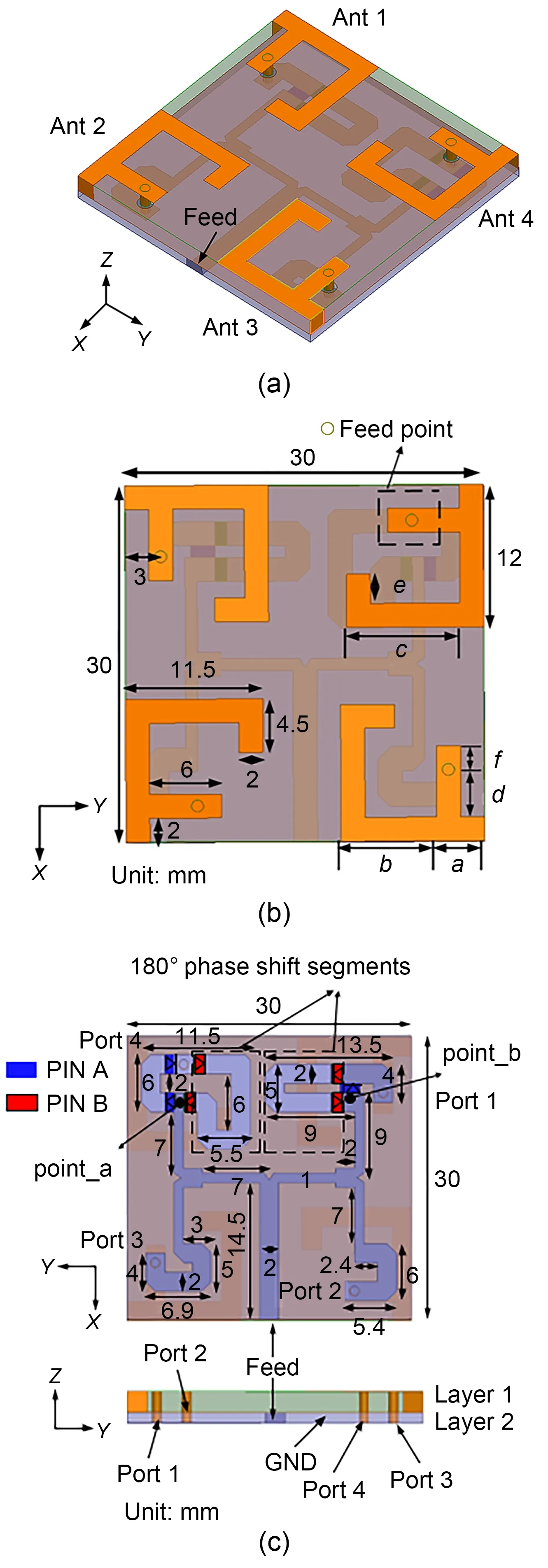
Fig.1 Geometry of the proposed array: (a) overall view;(b) antenna elements,top view;(c) controllable network,bottom and side views (References to color refer to the online version of this figure)
2.2 Antenna element design
Near the feed point,a short stub (microstrip line in Fig.1b) is set as a matching circuit.We use High Frequency Structure Simulator (HFSS) (Ansys Version 15) to optimize the parameters for the antenna element.The optimized parameters are as follows:a=4 mm,b=8 mm,c=9.5 mm,d=4 mm,e=2.5 mm,andf=2 mm.The total length of the current path for the antenna to resonate at 5.8 GHz is 30 mm,which is about one wavelength at 5.8 GHz.
The wavelength (λ) can be determined by
2.3 Omnidirectional radiation array design
As shown in Fig.2,the surface currents distributed on single-antenna elements contain two orthogonal components,and the expression of the currents can be assumed as
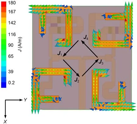
Fig.2 Surface current distribution on the antenna array for omnidirectional radiation mode (References to color refer to the online version of this figure)
wheref(x) orf(y) is the current distribution of a halfwave antenna,Iis the amplitude of the current,and j means that the current phase difference in theXandYdirections is 90°.So,the total electric field of the antenna element can be written as
For the antenna element,the length of the surface currents in theXandYdirections are nearlyλ/2,and for the half-wave antenna,we have
Therefore,the total electric field of the antenna element can be written as
According to Eq.(6),the E-field of a single element acts as a circle in theXY-plane (omnidirectional).So if the four antennas are fed with the same amplitude and phase,the synthetic total field can still achieve omnidirectional radiation characteristics.
When +1.8 V direct current (DC) voltage is applied to point_a and point_b through bias circuits,diodes of PIN A are on and diodes of PIN B are off,the amplitude and phase of the input power for the four ports are the same,the array can achieve horizontal omnidirectional radiation parallel to the human body (XY-plane),and can effectively receive creeping waves that propagate along the human body surface.Surface current distribution can be used to further analyze the working mechanism of the array.In Fig.2,J1represents the total vector sum of the leftward and downward surface currents that distribute on ant 1,J2represents the total vector sum of the rightward and downward surface currents that distribute on ant 2,J3represents the total vector sum of the rightward and upward surface currents that distribute on ant 3,andJ4represents the total vector sum of the leftward and upward surface currents that distribute on ant 4.The four total vector sum currents form a loop current.This is similar to the performance of a magnetic dipole,which radiates omnidirectionally in theXY-plane.
2.4 Directional radiation array design
To realize directional radiation,we first establish a wireless transmission system using the power transmission efficiency method (Jiang et al.,2016).The system is depicted in Fig.3;the aforementioned fourelement array is used as the transmitting antenna,and a dipole (resonant at 5.8 GHz) is introduced as a receiving antenna.The dipole is placed in the far field of the transmitting antenna in a specified direction.In this case,the antenna array is designed to radiate normally to human body surfaces,which is suitable for receiving off-body communication signal waves,or waves that are scattered by the ground,the walls,and so on.Therefore,during simulation,the dipole is placed in the +Zdirection,300 mm away from the transmitting antenna.
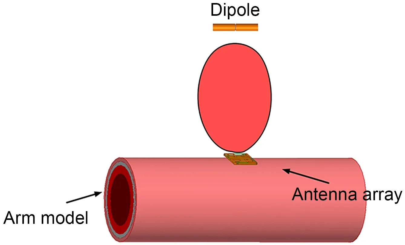
Fig.3 Power transmission between the four-element transmit‐ting antenna array and the receiving antenna (dipole)
The whole transmission system can be treated as a (4+1)-port network,and can be described by the scattering matrix as Eq.(7):
The subscripts t and r represent the transmitting antenna array and the receiving antenna (dipole),respectively.The normalized incident and reflected waves in the above formula can be expressed as
The ratio of the power received by the receiving antenna to the power input to the transmitting antenna array is defined as the power transmission efficiencyT,which can be expressed by
Because the test antenna is well matched at 5.8 GHz,we havear=0.When the power transmission efficiencyTreaches the maximum,according to Jiang et al.(2016) and Eqs.(7) and (9),Tcan be obtained by
whereAandBare two matrices defined by
Because at 5.8 GHz,the dipole and the transmitting antenna array are well matched,Eq.(10) can be further simplified to Eq.(12):
Through the HFSS simulation software,theSparameters for the transmitting antenna array and the receiving antenna can be obtained,and then substituted into Eq.(8).By solving Eq.(8),we can obtain the maximum transmission efficiency,Tmax,as the largest eigenvalue (because there is only one test antenna,Eq.(12) has only one positive eigenvalue,while the rest are zero because the rank ofAis unit).Meanwhile,the eigenvectoratcorresponding to the largest eigenvalue stands for the optimal excitation for each port of the transmitting antenna array.This method involves only port information,which can be obtained in the simulations and measurements.The complex environment and the coupling between antennas have been taken into consideration,which makes the method for obtaining the desired pattern of a wearable antenna array simple and effective.
During the simulations,when the amplitude and phase of the input power for the feed are set as 1 and 0°,respectively,to achieve a directional radiation pattern,the calculated amplitudes for the four ports are 0.49,0.51,0.50,and 0.50,while the phases are 179.3°,-2.5°,0°,and 178.1°.For simplicity,the four ports are designed to be fed with the same amplitude,and the phases for the four ports are adjusted to 180°,0°,0°,and 180°.
3 Antenna array measurements and further performance
3.1 Antenna measurements
The fabricated prototype of the antenna is shown in Fig.4.We use a ZNB 20 GHz two-port vector network analyzer to measure theSparameters of the array in free space and on an arm.When +1.8 V DC voltage is put on point_a (the black wire weld spot in Fig.4b) and point_b (the red wire weld spot in Fig.4b) through bias circuits,the omnidirectional model can be measured,and when -1.8 V DC voltage is put on point_a (the black wire weld spot in Fig.4b) and point_b (the red wire weld spot in Fig.4b),diodes of PIN A are off and diodes of PIN B are on,and the directional mode can be measured.As depicted in Fig.5,for both radiation modes,the measured resonance frequencies not attached to the human body shift slightly from the simulation results,which is caused mainly by the fabrication error and the difference among realistic dielectric material,PIN diodes,and the simulation models.When the array is mounted on the human body,for both modes,the resonance frequencies shift to a higher frequency.However,for all cases,the measured bandwidth can cover the targeted 5.8 GHz ISM band (5.725-5.875 GHz).
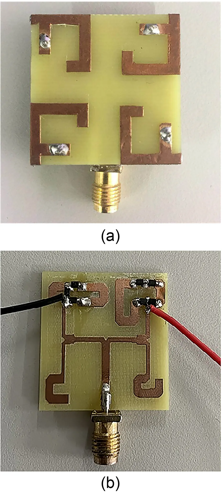
Fig.4 Fabricated prototype of the array: (a) top view;(b) bottom view (References to color refer to the online version of this figure)
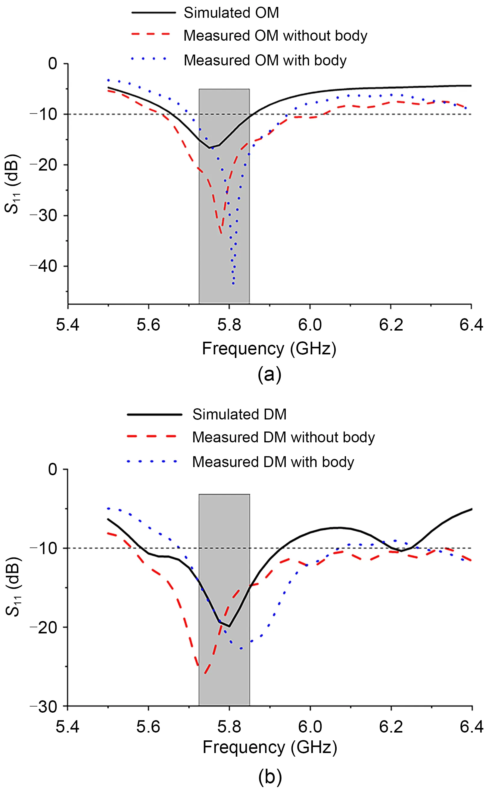
Fig.5 Simulation and measurement S parameters:(a) omnidirectional mode (OM);(b) directional mode (DM)
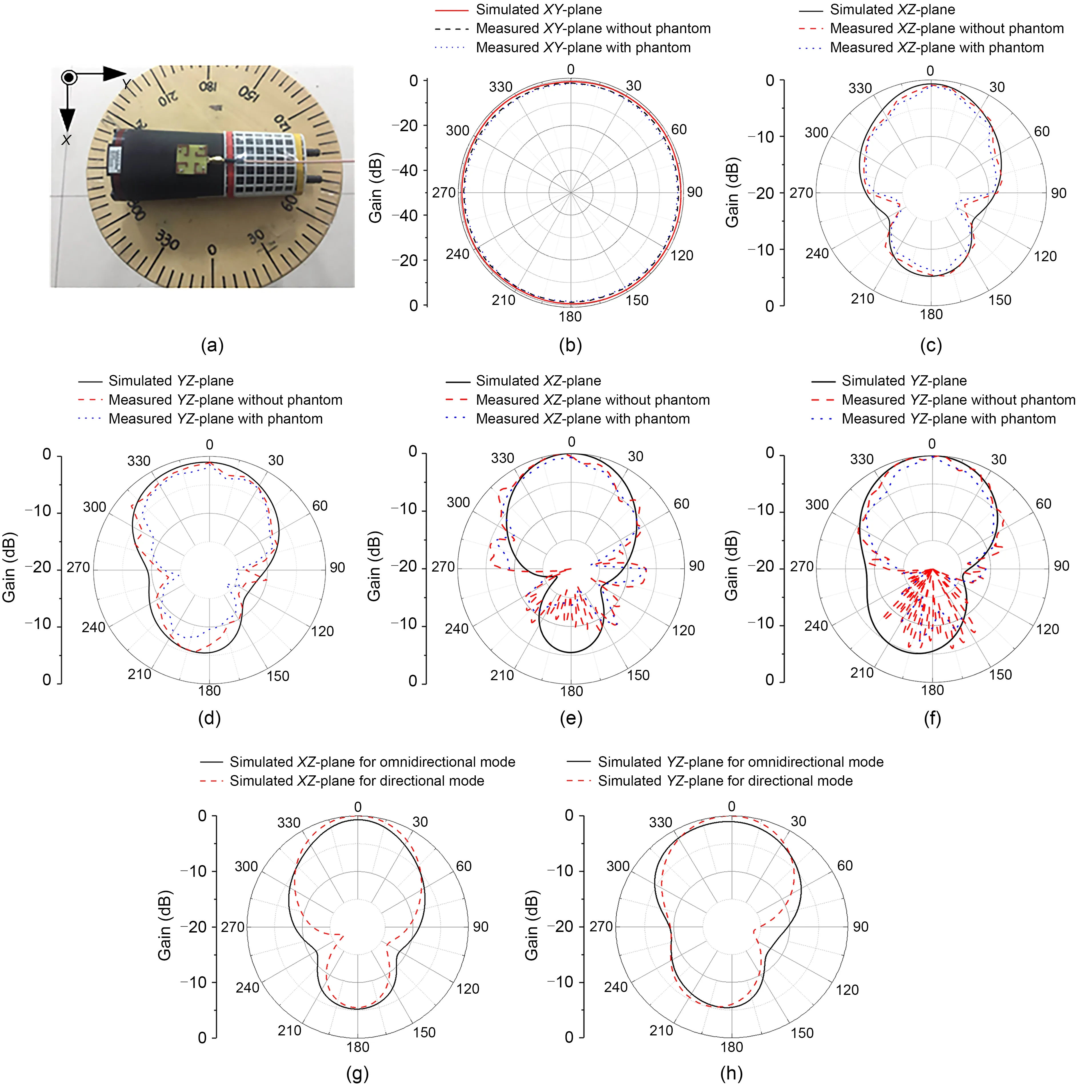
Fig.6 Radiation patterns for two modes of the array: (a) measurements of the antenna array on the forearm phantom;(b) XY-plane for omnidirectional mode;(c) XZ-plane for omnidirectional mode;(d) YZ-plane for omnidirectional mode;(e) XZ-plane for directional mode;(f) YZ-plane for directional mode;(g) comparison between simulated XZ-plane for two modes;(h) comparison between simulated YZ-plane for two modes
The radiation pattern is measured when the antenna array is mounted on a forearm phantom (Speag model SHO3TO6-LFPV2).The phantom has a frequency range from 3 to 6 GHz.For omnidirectional mode,as shown in Figs.6b-6d,the simulation and measurement results agree well,and omnidirectional radiation characteristics can be observed in theXY-plane.When the array is mounted on the forearm phantom,the gain is slightly reduced mainly due to the high loss of human tissue.For directional mode,the radiation patterns in theXZ-andYZ-plane are plotted in Figs.6e and 6f,respectively.We can see that the array radiates mainly to the +Zaxis direction,which is normal to human surfaces.Non-null radiation around broadside is obtained.From Figs.6g and 6h,we can see that compared with the directional mode,the lobe of the forward radiation pattern is wider in the omnidirectional mode.For omnidirectional mode,based on our design,after setting multiple receiving (test) antennas,the radiation pattern stretches in the four directions in theXY-plane.
In the 5.8 GHz ISM band,the measured gain with the forearm phantom varies from 1.7 to 2.1 dBi for the omnidirectional mode,and varies from 2.33 to 3.45 dBi for the directional mode.For both modes,the antenna array has the highest gain near the resonance point of 5.8 GHz.Simulated efficiencies in free space are 72% and 81% for the omnidirectional and directional modes,respectively,whereas measured values for the omnidirectional and directional modes reduced to 63% and 70% in the presence of the phantom.
3.2 Specific absorption rate evaluation
To ensure the safety of the antenna array when it is mounted on the human body,the SAR level should be analyzed.According to the Federal Communications Commission (FCC) guidelines,the SAR must be <1.6 W/kg averaged >1 g of human tissue (Lin et al.,2017).In this study,the SAR values of the array are also simulated via HFSS.Skin,fat,and muscle layers used in the three-layer human tissue model (Fig.7) are 1,2,and 10 mm,respectively.Their relative permittivities and conductivities are listed in Table 1.The antenna array is placed 5 mm above the human tissue model,and the input power to the array is 500 mW.For the directional model,the maximum SAR is 0.75 W/kg for averaged >1 g of body tissue at 5.8 GHz in the fat layer,which is higher than the maximum SAR values in the skin layer (0.23 W/kg) and muscle layer (0.03 W/kg).For the omnidirectional model,the SAR values in three layers are slightly higher,but they can all satisfy the FCC criterion.

Table 1 Dielectric properties of various human tissues at an operation frequency of 5.8 GHz
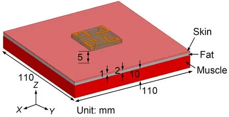
Fig.7 Simulated 1 g averaged SAR distributions with a three-layer tissue model
3.3 Beam switchable function realization
Recent studies have shown that arrays with beam switching capabilities are in demand for WBAN applications.Similar to directional radiation pattern design,based on a power transmission efficiency method,we can realize the beam switchable function by replacing the feed network with power dividers and phase shifters.Taking the beam switching angles of ±45° as an example,as depicted in Fig.8,test ant 1 is for the directional mode,while test ant 2 and test ant 3 are for-45° and +45°,respectively.Together with the antenna array and calculate the (4+1)-port network for test ant 2 and test ant 3.Using Eqs.(7)-(12),we can obtain the amplitude and phase information of the 4-port feed required in Table 2.

Table 2 Port amplitude and phase information required to realize the beam switching angle
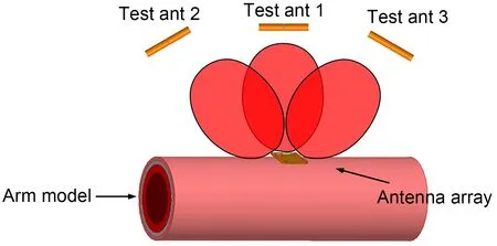
Fig.8 Antenna system setting for beam switchable function
When the amplitude and phase of the input power for the feed are set at 1 and 0°,to achieve a +45°beam switching angle,the calculated amplitudes for the four ports are 0.48,0.53,0.28,and 0.65,while the phases are -66.8°,47.8°,-140°,and 0°.Meanwhile,to obtain -45° beam switching angle,the calculated amplitudes for the four ports are 0.28,0.65,0.48,and 0.53,while the phases are -140°,0°,-66.8°,and 47.8°.
By bringing the above port amplitude and phase information into HFSS for simulation,we can obtain the beam switchable function (Fig.9).We can see that the radiation pattern of the array switches to the aimed angle,while the front-to-back ratios are at a similar level.Because all the port information can be calculated in advance,we can ensure that even without the fixed microstrip feed network,omnidirectional and directional patterns can still be realized.According to our design,when the test antenna is relocated,the beam can be shifted in the aimed direction.Because there are only four antenna elements and the antenna element beam is not narrow,the effective beam steering range is about -60° to 60°.
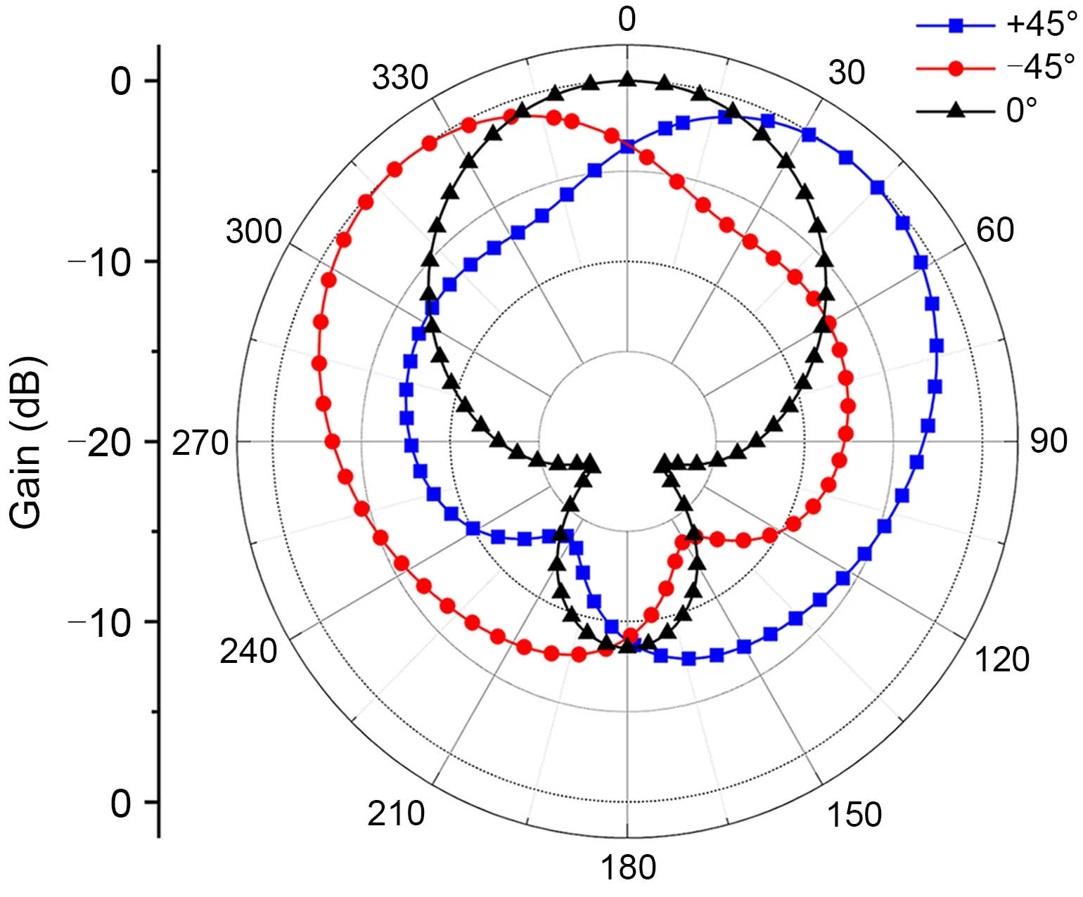
Fig.9 Simulated switchable radiation patterns for the array
4 Conclusions
A four-element antenna array with pattern diversity for 5.8 GHz wearable applications is proposed in this paper.By changing the working states of the PIN diodes,the array can switch between two radiation patterns: the omnidirectional radiation pattern in the plane tangent to the body surface,which is suitable for on-body communication applications,and a radiation pattern normal to the body surface,which is appropriate for off-body communication applications.When the array is attached to the human body or arm phantom,the measurement results such as impedance bandwidth and radiation patterns agree with the simulation results and can satisfy the design goal.Moreover,the simulated SAR values for both modes are below the FCC’s standard threshold.Also,the methods used to design the directional mode can be simply extended to realize beam switchable functionality.By calculating theSparameters of the system composed of the virtual test antenna at the target position and replacing the feed network with feeding circuits including power dividers and phase shifters,the beam can be easily switched to the target angle.
Contributors
Lingsheng YANG and Yajie LI designed the research.Bin WANG processed the data.Lingsheng YANG drafted the paper.Yajie LI revised and finalized the paper.
Compliance with ethics guidelines
Lingsheng YANG,Bin WANG,and Yajie LI declare that they have no conflict of interest.
Data availability
The data that support the findings of this study are available from the corresponding author upon reasonable request.
 Frontiers of Information Technology & Electronic Engineering2023年9期
- Frontiers of Information Technology & Electronic Engineering的其它文章
- Matrix-valued distributed stochastic optimization with constraints∗
- Distributed optimization based on improved push-sum framework for optimization problem with multiple local constraints and its application in smart grid∗
- A home energy management approach using decoupling value and policy in reinforcement learning∗
- Exploring nonlinear spatiotemporal effects for personalized next point-of-interest recommendation
- LDformer: a parallel neural network model for long-term power forecasting*
- Mixture test strategy optimization for analog systems∗#
