
Numerical investigations of the failure mechanism evolution of rock-like disc specimens containing unfilled or filled flaws
2023-02-06 07:06TianWANGJianWANGShengJIANGJiaheZHANG
Tian WANG, Jian WANG, Sheng JIANG,2, Jiahe ZHANG
Regular paper
Numerical investigations of the failure mechanism evolution of rock-like disc specimens containing unfilled or filled flaws

1College of Water Conservancy and Hydropower Engineering, Hohai University, Nanjing 210098, China2School of Civil Engineering, The University of Sydney, Sydney, NSW 2006, Australia
The mechanical responses and ultimate failure patterns of rocks are associated with the failure mechanism evolution. In this study, smoothed particle hydrodynamics (SPH) method with the mixed-mode failure model is proposed to probe into failure mechanism evolutions for disc specimens upon loading. The tensile damage model and the Drucker-Prager model are used to calculate the tensile failure and shear failure of the material, respectively. It is concluded that for flaw-unfilled disc specimens, the crack coalescence mechanism in the rock bridge area is affected by the flaw inclination angle and the material property. Considering disc specimens with filled flaws, the incremental rate of tensile damage grows more rapidly when the disc and filling material have a closer ratio of tensile strength to cohesion, which makes the entire specimen response greater brittleness. Furthermore, with the increasing non-uniformity of filling distribution, the incremental rate of tensile-activated damage decreases and the disc specimen performs more ductile. Besides, the influence of the fillings is greater when the flaw inclination angle is approaching 45°. It is proved that the proposed SPH method can be used to simulate the failure mechanism evolution of rocks, which lays a foundation for the study of more complex rock failure.
Smoothed particle hydrodynamics (SPH); Mixed-mode failure model; Failure mechanism evolution; Crack coalescence; Filling distribution
1 Introduction
Substantial pre-existing flaw induced heterogeneity widely exists in natural rock masses and may span over multiple scales (Ichikawa et al., 2001). Under some environmental circumstances, these opening flaw apertures are naturally filled with different fine-grained materials due to weathering or joint shearing (Sharafisafa et al., 2019). The main effect of the rock heterogeneity induced by opening flaws or fillers is the generation of local tensile stress concentration even when the rock is only subjected to compressive loading (Miao et al., 2018). These local tensile cracks are believed to be the primary mechanisms of crack initiation, propagation, and coalescence in most scenarios (Wong and Einstein, 2009b). Nevertheless, when sufficient tensile damage has been generated or the applied confining pressure is sufficiently high, shear cracking starts to prevail and becomes dominant (Shen et al., 1995).
Consequently, compared with the intact rock, the macroscopic mechanical properties of these heterogeneous rocks are different, and are associated with the alternations of deformation behaviors and ultimate failure patterns upon loading. Issues pertaining to heterogeneous rock fracturing events are widespread in many fields. Rock fracture is very common in large deformation problems. For instance, in the geotechnical field, a sliding surface triggered by dynamic loads or heavy rainfall in jointed rock mass may induce rock slope instability, which eventually leads to landslides (Pal et al., 2012). In underground construction projects, the occurrence of rock fracture initiation, propagation, and coalescence should be avoi ded to prevent collapse during the excavation of mines and tunnels (Cai et al., 2004; Zheng et al., 2021). In contrast, for the extraction of oil or gas in the petroleum industries (Adachi et al., 2007), hydraulic fracturing is used as a basic technique to boost the well to maximize extraction.
Conventional laboratory-based investigations are usually the most straightforward approach to evaluating the fracture behaviors of flawed or flaw-filled rocks (Yu et al., 2015). The topic of interest focuses on the effects of opening flaws or fillers on rock fracturing in terms of different pre-existing crack configurations, such as crack geometry (Wong and Chau, 1998; Afolagboye et al., 2018), number (Tang et al., 2001; Zhou et al., 2014), orientation (Wong and Einstein, 2009b), and filling materials (Zhao and Zhou, 2016; Lei et al., 2020). Zhao et al. (2016) conducted a series of uniaxial compression tests on rock-like specimens containing two parallel flaws. The experimental results highlighted that the flaw angle associated with the bridge angle determines the peak strength and cracking coalescence patterns. As for rocks with three fissures, Wong et al. (2000) analyzed the coalescence characteristics through experiments, which mainly focus on the influence of confining pressure. Rock fracture behaviors become more complex with the complicated interactions from rock-flaw-filling (Zhao et al., 2022). The presence of filler will change the stress state of the flaw and further enhance the rock heterogeneity, making a significant difference from the unfilled cases. Pan et al. (2020) studied the influence of infilling conditions on flaw surface relative displacement and on induced cracking behaviors, such as crack initiation, propagation, and crack patterns. They concluded that with the increase of fillers' stiffness or flaw inclination angle, the effect of relative tangential displacement gradually plays a dominant role in cracking behavior. Miao et al. (2018) observed the damage process of sandstone specimens with different filling materials and studied the compressibility effect of fillings on cracking behavior through analysis of the displacement and strain fields of the flawed specimens.
Nevertheless, the experimental approach is usually time-consuming for specimen preparation and test setup (Haeri et al., 2014). This drawback will be more problematic for investigating high dimensional variables. For some especially fragile or heavily weathered rocks, it may be difficult to obtain an adequate number of high-quality formed experimental samples. Also, systematic errors cannot be eliminated during the sample preparation process, including unexpected micro-damage or micro-cracks, leading to bias in the experimental results (Sharafisafa et al., 2018). Therefore, the numerical approach is an alternative to replicating experiments for predicting coupled effects of flaws and fillers on rocks. Rather than the peak load and failure pattern, extra information, such as the stress distribution and fracture evolution, is also accessible from the numerical results enhancing the interpretation of the experimental observations (Zhang and Wong, 2012; Lin et al., 2015). Xu and Chen (2016) modelled the multiphase distribution in the meso-structure with the finite element method (FEM), which closely mimics the mechanical response and damage behavior of concrete. However, methods based on that method are not ideal for large deformation problems (Yin et al., 2021). Tian and Yang (2017) pointed out, by numerical simulation using the 2D particle flow code (PFC2D), that shear coalescence is prone to occur at specific ligament and fissure angle ranges. Sharafisafa and Nazem (2014) stated that the discrete element method (DEM) can simulate secondary crack formations and associated crack coalescence patterns well. To understand the influence of tensile crack and shear crack initiation in the cracking process, Zhang and Wong (2012) used the bonded-particle model (BPM) approach to simulate the axial compression of a rock mass with a single pre-existing fracture. Those methods are all based on the discrete element approach. Due to its high calculation cost, DEM is not widely used in simulating large-scale deformation problems. The calculation of DEM adopts many microscopic particle parameters, which requires multiple parameter calibration before calculation (Zhang et al., 2015). It is not convenient for application in practical engineering and cannot be used as a reference for the value of material parameters in such circumstances.
Wang YN et al. (2019, 2020) and Wang T et al. (2020) mentioned that the smoothed particle hydrodynamics (SPH) has value in simulating the generation and propagation of cracks in solid materials. Also, the application of the SPH method in simulating rock-like specimens lays a foundation for the study of more complex rock failure, such as landslides. However, to date, most studies mainly pivot on the failure phenomena of heterogeneous rock-like samples. Less attention is paid to the evolution of the failure mechanism upon loading. The fragmentation of the heterogeneous rock samples is controlled by various fracture mechanisms that depend on their material properties (Ma et al., 2018). These evolving behaviors of the diverse fracture mechanisms ultimately manifest as the discrepancies of failure patterns and mechanical properties (Zhao and Zhou, 2016). The objective of this study is to numerically investigate the failure mechanism evolutions of both flaw and flaw-filled rock-like materials in the Brazilian disc test. The SPH method is utilized to tackle this problem by introducing the mixed-mode fracture model. The coupled effects of different disc materials, flaw inclination angles, and filling material properties on the rock-like disc sample fragmentation are investigated to study the evolution of the underlying failure mechanism. The associated mechanical properties and failure patterns are compared and discussed to highlight these coupled influences.
2 Methodology
SPH is a Lagrangian meshless method and is suitable for large deformation problems. Since its invention to solve astrophysical problems (Gingold and Monaghan, 1977; Lucy, 1977), it has been widely applied in many fields (Libersky et al., 1993; Cleary, 1998; Potapov et al., 2009; Wang and Chan, 2014; Yeylaghi et al., 2017; Jin et al., 2021) and has certain applications in the field of rock fracture (Das and Cleary, 2010, 2015; Das et al., 2014; Douillet-Grellier et al., 2017) and even in multiphase materials (Douillet-Grellier et al., 2016).
The governing equations of SPH method and the SPH approximation are provided in Sections S1 and S2 of the electronic supplementary materials (ESM). In this study, many techniques are adopted to avoid tensile instability in the simulation, which are described in Section S3 of the ESM.
2.1 SPH kernel correction
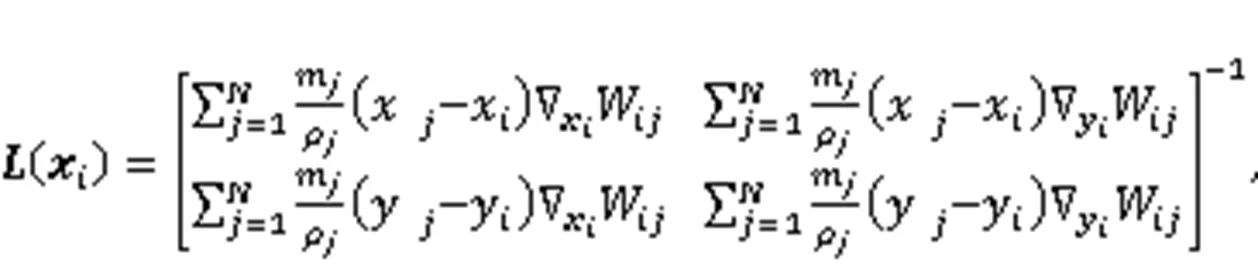
A corrective smoothed particle method (CSPM) derived from the Taylor expansion is applied to handle the particle deficiency at boundaries in the SPH calculation (Chen et al., 1999). Smoothing kernel functionin Eq. (S3) of the ESM and the gradient of the kernel function ∇in Eq. (S5) of the ESM can be replaced byCand ∇C, as follows:
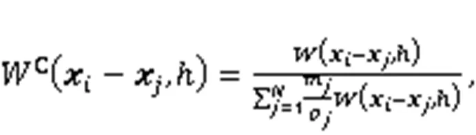
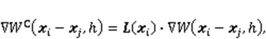
whereis the smoothing length;mandρare the mass and density values of particlein the support domain;andare the positions of particleand particle, respectively;() is the normalization matrix, and its 2D formation is as follows:
For the sake of simplicity, a detailed elaboration with respect to SPH can be found in (Bui et al., 2008).
2.2 Constitutive model for rock-like materials
The brittleness characteristic of rock-like materials mainly results from the dominant position of the tensile failure upon loading. Plastic deformation can also occur due to rock ductility and consequently develops into shear failure (Deb and Pramanik, 2013). To fully capture the complex damage phase in the rock-like materials, a coupled mixed-mode failure model is integrated with SPH. To be specific, the Drucker-Prager (D-P) model is employed for describing the elastoplastic behaviors of rock-like materials, as well as the damage activated by shear. The damage behavior induced by tensile failure is determined by the tensile damage model. To distinguish between tensile failure and shear failure, the damage variableis further subdivided into the tensile damage variabletand the shear damage variables.
The ideal elastoplastic constitutive model is given in Section S4 of the ESM.
2.2.1D-P model
The D-P yield criterion is used to determine the initiation of the plastic deformation (Bui et al., 2008). This applied yield criterionmodifies the original Mohr-Coulomb yield function to eliminate the singularities caused by sharp angles, as follows:
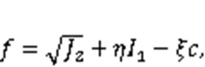
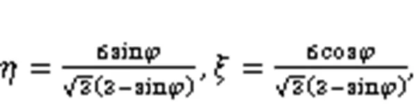
whereandare the constants in the D-P model, related to the friction angle;is the cohesion;1and2are the first invariant of the stress tensor and the second invariant of the deviatoric stress tensor, respectively. D-P model parameters of geotechnical materials can be obtained by the triaxial test.
The plastic potential functionand the stress–strain expression of the D-P model are given in Section S5 of the ESM.

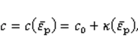
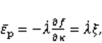
The degree of shear damage is determined by the plastic strain calculated in the D-P model as follows:

2.2.2Tensile damage model
The criterion of particle tensile failure is defined as:
wheretis the material tensile strength, andmaxis the maximum principal stress.
Once the initial crack is generated, the tensile damage variabletof a particle will evolve with its relative displacement. The stress–displacement relationship of the damaged particle is a two-line cohesive model (Ma et al., 2018):
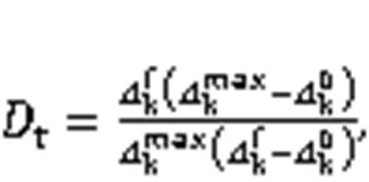
The tensile damage variabletis a scalar.t=0 indicates the material is intact. When the maximum normal stress of the particle reaches the tensile strength of the material, cracks initiate in the material. The tensile damage variable will gradually increase to 1 until a complete tensile damage state is reached and particles cannot suffer any tensile stress (Benz and Asphaug, 1995).
When the particle has tensile damage and shear damage, the particle is in the mixed-mode damage state, i.e.,t·s≠0, so that bothtandsrepresent the damage degree of the particle. To couple the D-P model with the tensile damage model, it is necessary to remove the tensile part from the D-P model to avoid conflict with the tensile damage model (Douillet-Grellier et al., 2016).
3 SPH model validation
To validate the accuracy and applicability of the proposed SPH model, a detailed study has been performed. The accuracy of SPH method is firstly verified by comparing it with the analytical solution in Section S6 of the ESM.
In this study, the smoothing lengthis set as 1.2Δwith the cubic spline kernel, where Δis the initial particle space. All the simulations are carried out with artificial viscosity termsΠandΠtaken as 1.0 to improve numerical stability and damp out undesirable oscillations (Monaghan, 1992). The exponentin the artificial stress method is taken as 0.2. The tension cracking treatment and stress-rescaling procedure are also adopted in simulations to bring the stress state back to the yield surface (Chen and Mizuno, 1990).
The proposed SPH algorithm is then verified by implementing the mixed-mode failure model through simulations of the Brazilian disc test with double unfilled (or filled) flaws. The simulations of discs with flaws are conducted to calibrate the material parameters and to verify the applicability of the proposed SPH method in three different flaw inclination angle cases, namely 0°, 45°, and 90°.
Fig. 1 depicts the schematic view of the double-flaw disc configuration with 8-mm flaw length and 6-mm gap distance. The individual flaw width is 0.6 mm. The applied loading is controlled by displacement of an upper panel at a constant speed of 1 mm/s. In the SPH simulation, the translational rigid body with zero friction force is adopted as the displacement boundary (Wang et al., 2013; Wang and Chan, 2014). Material mechanical properties adopted here refer to the study of Sharafisafa et al. (2019), as listed in Table 1. The tensile strength, cohesion, and friction angle of the rock-like material are determined by parameter calibrations to guarantee the peak loads simulated by the SPH are close to the experimental results. Fig. 2 illustrates that, other than in the case of unfilled flaws (=45°), the peak load errors between the SPH simulation and experiment are all less than 4.5%. Fig. 3 shows the post tensile failure diagrams for different cases. The tensile failure patterns fit well with the maximum tensile strain contours of the experiment. For the case of coplanar filled flaws, the initial crack is generated from the filled flaw tip and then runs through the disc when≤45°, while in the experiment, the crack does not pass through the filled flaw area. The difference lies in the stress concentration of the simulation, resulting in deviation of the initial crack location. Corresponding shear failure contours and analysis are demonstrated in Section 4. The accordance of failure pattern and peak load of the SPH simulations and experiments indicates the applicability of the SPH simulation.
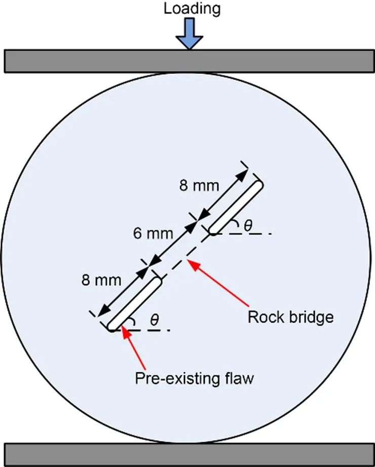
Fig. 1 Schematic diagram of the disc with double flaws. θ is the flaw inclination angle
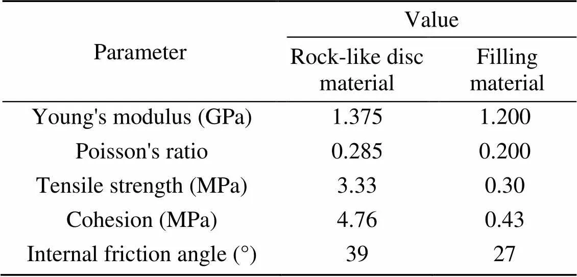
Table 1 Mechanical properties of rock-like disc material and filling material
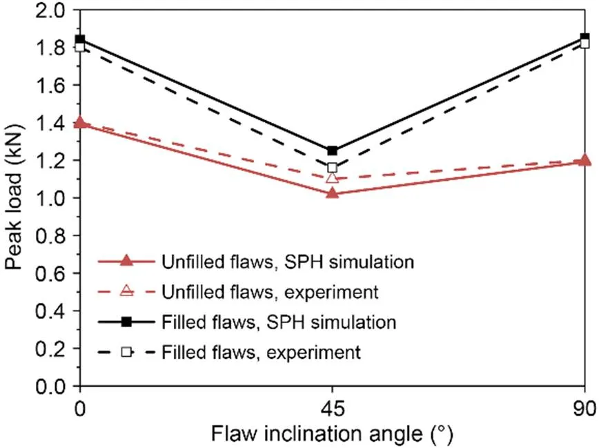
Fig. 2 Peak load of specimens with unfilled or filled flaws derived from SPH simulation and experiment
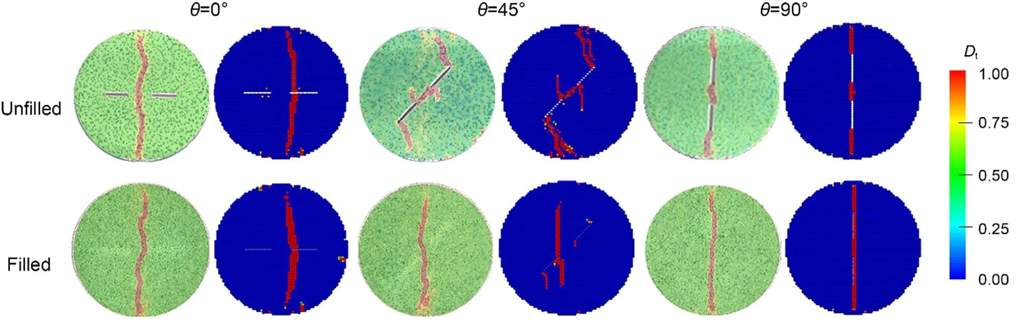
Fig. 3 Tensile failure diagrams of disc specimens with unfilled or filled flaws (discs in green: experimental results; discs in blue: SPH simulation results). References to color refer to the online version of this figure
In this study, in order to verify the convergence of the simulation and to validate the rationality of the smoothing length, different particle discretization sizes and smoothing lengths are used for the unfilled flawed disc (=45°) simulations, which are shown in Section S7 of the ESM.
4 Case studies of fracture mechanism evolutions
To investigate the failure mechanism evolutions of disc specimens containing unfilled or filled flaws, case studies are performed by varying the mechanical properties of both disc material and filling material, as well as the flaw inclination angle. According to previous experimental results, the failure patterns in the Brazilian disc tests with double flaws are basically of two types: crack coalescence formed in the bridge area or a through-running failure band initiated from the disc center (Sharafisafa et al., 2019). When≤30° in unfilled cases or≤45° in filled cases, the failure patterns are all classified as through-running failure bands (Gui et al., 2015). In order to distinguish the two fracture modes in the following analysis of the coalescence mechanisms, the flaw inclination angle of unfilled cases spans over 35° to 90° and the flaw inclination angle of flaw-filled cases is chosen from 0° to 45° to emphasize the through-running failure band.
Hereafter, the geometrical setup of the remaining simulated problems is the same as in Fig. 1 and the loading rate is set as 1 mm/s. All the parameters of the SPH simulation setup are the same as in Section 3. In addition, for the purpose of valid comparisons, only the shear strength related parameters (cohesion and internal friction angle) are changed, while other mechanical properties are kept unchanged, as listed in Table 1.
4.1 Flawed disc case
For a comprehensive study of different types of material, three combinations (Cases I, II, and III) of cohesion and internal friction angle are selected, representing the gradual transformation of disc material properties from brittleness (Ma et al., 2018) to ductility (Chen and Shen, 2022). Considering that a ductile material usually has a smaller internal friction angle than a brittle one, the internal friction angle value varies along with the cohesion. The ratio of disc material tensile strength to the cohesion, denoted byr, is implemented as the index to represent different combinations. Table 2 summarizes the material properties for different cases. The flaw inclination angles are selected as 35°, 45°, 60°, 75°, and 90°, respectively.
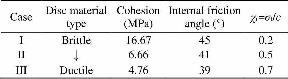
Table 2 Parameters of the disc material in the three cases
tdenotes the tensile strength of the disc material anddenotes the cohesion of the disc material
4.1.1Failure mechanism evolutions
Considering that the damage factor is calculated by the relative displacement, the strain value can reflect the damage state. For tracing the complete crack coalescence process, the strains of two representative points (P1 and P2) in the bridge area are analyzed, where points P1 and P2 are as labeled in the inset of Fig. 4a.
For the ductile material (Case III), Figs. 4a–4c are the strain histories at representative points and failure evolution diagrams under different flaw inclination angles (45°, 60°, and 90°). As shown in Fig. 4a, for=45°,after reaching the peak load, some tensile damage appears in the center of the rock bridge region, which is also reflected by the abrupt change of tensile strainεat P1. A small amount of shear failure is also discovered at the flaw tips at this stage. Upon continuing loading, the central tensile cracks keep propagating towards the flaw tips and the initial shear failure gradually turns into shear damage. Consequen tly, initial tensile-activated cracks gradually transform into the mixed-mode fracture and generate the ultimate crack coalescence mode.
For the=60° case depicted in Fig. 4b, tensile-activated cracks have already been produced in the middle of the rock bridge before the disc specimen reaches its peak load, and they soon shift into mixed-mode fractures. The sharp increase of tensile strainεat P1 is earlier than that at P2, indicating that crack coalescence extends from the center of the disc specimen to the flaw tip. Besides, P2 experiences more severe change of shear strainεthan P1, which is different from the 45° case. This evidence indicates that when=60°, the crack coalescence mode at the rock bridge is a mixed-mode activated fracture; the 45° case is more shear dominant than the 60° case.
In terms of=90°, shear strainsεat P1 and P2 hardly evolve before the peak load, as shown in Fig. 4c. The sharp increase ofεof both P1 and P2 reflects the tensile dominant state of the coalescence mode.
In conclusion, tensile failure is generated from the center of the rock bridge area, while shear failure tends to initiate from the pre-existing flaw tip. With the decrease of flaw inclination angle, there will be more shear failure generated from the flaw tip, which leads to the transformation of the crack coalescence mode from tensile failure dominant to shear failure dominant.
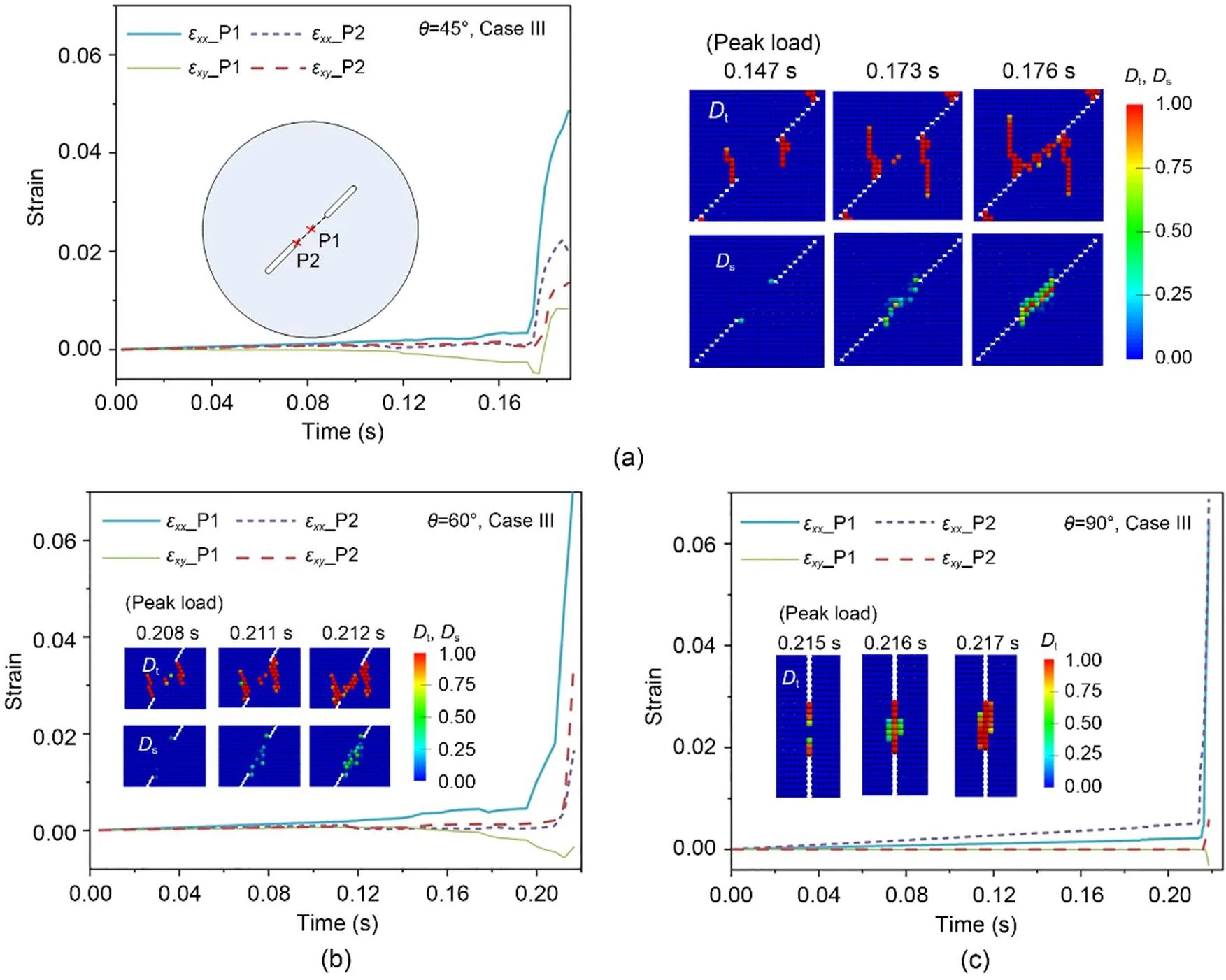
Fig. 4 Diagrams of tensile strain εxx and shear strain εxy histories at characteristic points of three typical disc specimens in the SPH simulations, and the corresponding crack coalescence processes in the rock bridge area of the disc specimens: (a) θ=45°, Case III; (b) θ=60°, Case III; (c) θ=90°, Case III
For brittle material (=60°, Case I) in Fig. 5, the initiation of tensile crack coalescence is at the center of the disc specimen. It merges with tensile-activated wing cracks in the middle of the disc specimen, connecting the pre-existing flaws and forming a crack coalescence, during which the bearing capacity of the disc specimen greatly declines. There is no significant change of shear strainεat P1 and P2 during the loading process. Also, because no sudden increase is found in the tensile strainεof P2, the tensile fracture in the middle of the disc specimen has not fully penetrated to the pre-existing flaws.
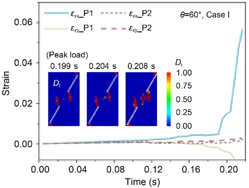
Fig. 5 Diagrams of tensile strain εxx and shear strain εxy histories at characteristic points of disc specimen in the SPH simulation, and the corresponding crack coalescence processes in the rock bridge area (θ=60°, Case I)
Comparing Figs. 4b and 5, it can be concluded that for=60°, when the material property changes from brittle to ductile, the mechanism evolution of crack coalescence mode at the rock bridge gradually changes from tensile failure to mixed-mode failure after the peak load.
With the coupled effect of flaw inclination angle and material type, the failure mechanism evolution in the disc specimen's rock bridge area is gradually transformed. Besides, in Figs. 4 and 5, when=45°, the abrupt change ofεandεat P1 or P2 happens after the peak load while, when>60°, it happens earlier than the peak load, thus indicating that for disc specimens with a relative high flaw inclination angle, the crack coalescence occurs before the peak load, which coincides with the results in (Sharafisafa et al., 2019).
4.1.2Crack coalescence mechanisms
Table 3 lists the crack coalescence modes of disc specimens with different material properties and flaw inclination angles. With the decrease of the flaw inclination angle (90° to 35°), the crack coalescence mechanism will gradually transform from tensile failure dominant to shear failure dominant, which agrees with the analysis of failure mechanism evolution. At a given flaw inclination angle (<60°), the material shows more brittleness and the more difficult the crack coalescence is to occur in an unfilled flaws disc, indicating that crack coalescence is mainly caused by shear failure. When the inclination angle of the flaw is around 60°, with material property changes from brittle to ductile, the type of crack coalescence at the rock bridge area changes from tensile failure to mixed-mode failure, which accords with the failure mechanism evolution analysis in Section 4.1.1, and proves that the fracture mechanism evolutions determine the crack coalescence type of the disc specimen. For the cases with high flaw inclination angle, tensile failure is mainly found in the area of the rock bridge. Fig. S7 of the ESM shows the characteristic post-failure diagrams of disc specimens with different crack coalescence modes.
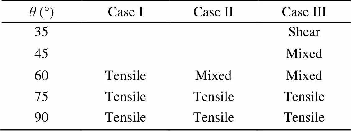
Table 3 Crack coalescence modes in the rock bridge area
4.2 Flaw-filled disc case
The failure mechanisms of the disc specimens are statistically analyzed to quantitatively evaluate the failure process for flaw-filled disc specimens. The effects of the strength of the fillings and the non-uniform filling distribution are both discussed in this section. The flaw inclination angles are selected as 0°, 15°, 30°, and 45°. The ratio of fillings' tensile strength to cohesion, denoted byf, is used to describe the property of the filling material. Since most of the rock fillings in nature have weaker material properties than the rock itself, the range offchosen here is from 0.5 to 1.2.
4.2.1Uniform distributed filling material
By simulating various tests of discs with filled flaws, the influence of different fillings on the failure mechanism evolutions of the disc can be studied. The parameters of the filling material in different cases are tabulated in Table 4.
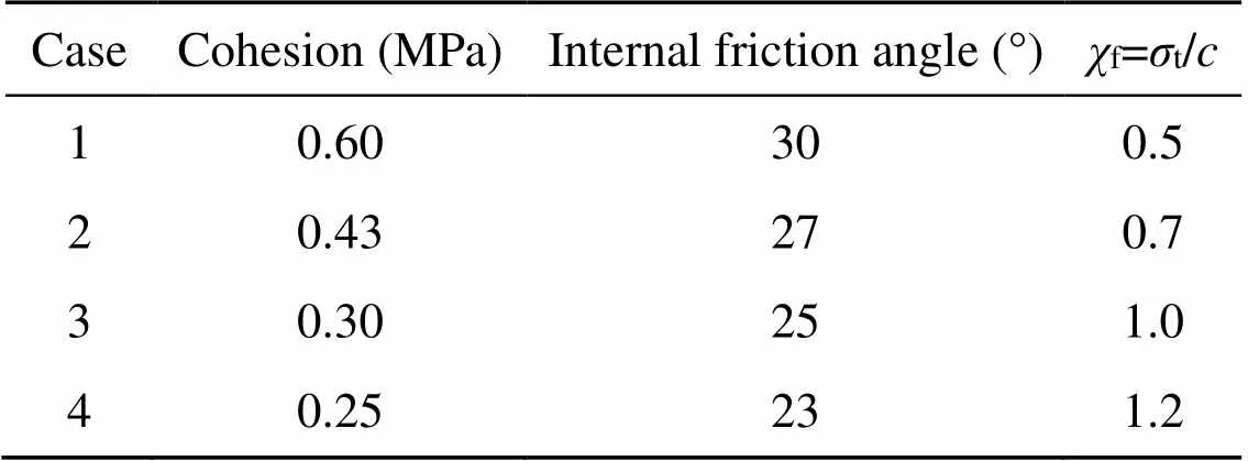
Table 4 Parameters of the filling material
tdenotes the tensile strength of the filling material anddenotes the cohesion of the filling material
4.2.1.1Failure mechanism evolutions
To describe the failure process of disc specimens over the progressive failure process, Fig. 6a presents the typical evolutions of damage ratiosof disc specimens (=30°, Case 1), in which, tensile, shear and mixed-mode damage ratiosH,H, andHrefer to the ratio of the respective damaged particle number to the total particle number. The failure process of the disc specimen is generally divided into the ascending stage and the plateau stage in Fig. 6a. The ascending stages differ, but the initiations of the plateau stages forH,H, andHare almost the same. It is assumed that the entire time periods of the ascending stages of tensile damage, shear damage, and mixed-mode damage are Δt, Δt, and Δt, respectively. The damage ratio incremental rates Δ/Δin the ascending stage of disc specimens (=30°) versus different fillings are plotted in Fig. 6b. Fig. 6b shows that the disc specimen of Case 2 (f=0.7) has the lowest incremental rate of shear damage ratio and the highest incremental rate of mixed-mode damage ratio, while the disc specimen of Case 4 (f=1.2) is the opposite. In it, the mixed-mode damage is all tensile dominant. The variation trend of shear damage ratio incremental rate with the type of fillings is opposite to that of the mixed-mode damage. However, the incremental rate of shear damage is less influential compared to that of tensile dominant damage. The results show that whenfof the fillings is close torof the disc, the incremental rate of tensile dominant damage is larger.
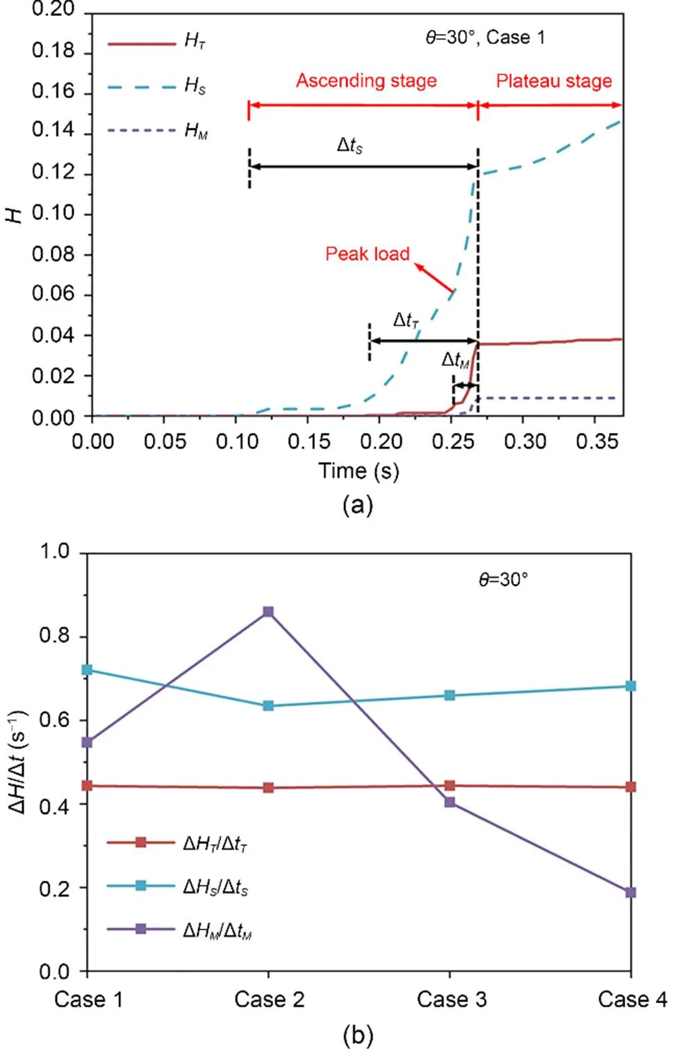
Fig. 6 Evolutions of damage ratios H of the disc specimen (θ=30°, Case 1) (a) and incremental rates of damage ratio for disc specimens (θ=30°) (b) under different types of fillings
For further analysis of the coupled effect of the strength of the fillings and the flaw inclination angle on the proportion of different types of damage, Fig. S8 of the ESM shows the comparison diagrams of the proportions of damage at peak load and post-failure. The proportions of particle numbers in tensile, shear, and mixed-mode damage states to the total number of damaged particles in the disc specimens (excluding filling material) are represented by,, and, respectively, where++=1.
As can be seen from Fig. S8a of the ESM,increases with the increase of flaw inclination angle at peak load, whiledoes the opposite. When the strength of the filling material is the weakest,of the disc specimen is the largest andis the minimum at peak load. At peak load,is relatively small and below 2%.is the largest at=30°.
After the disc specimen reached peak load, it continued to be loaded for 24.56 ms to reach post-failure state. The proportions of particle numbers in tensile, shear, and mixed-mode damage states to the total number of damaged particles are illustrated in Fig. S8b of the ESM. When=0°, as the filling material strength weakens,increases anddecreases. When>0°, the changes ofandwith the fillings are opposite to those when=0°. The particle numbers in the mixed-mode damage state increase after peak load and the rate of increase is the largest at=15°.
The analysis above indicates that the strength of filling material has a certain influence on the proportions of different failure mechanisms in the disc specimens and may change the overall distribution of cracks in some cases. That influence is greater when the flaw inclination angle in the disc specimen is close to 45°. The effect increases with the decrease of filling strength. When the filling strength is very weak, the tensile failure of the disc specimen increases significantly at=45°.
4.2.1.2Mechanical responses and failure patterns
The differences in peak load of cases with differentfare within 8%, proving that the material property of the fillings has little influence on the peak load value of the disc specimens. It can be seen from Fig. 7 that the crack initiation strength ratio (Wong and Einstein, 2009a) is almost 1 at=0°, illustrating that the disc specimen has reached its maximum bearing capacity when the first crack occurs in the disc. With the flaw inclination angle increased to 45°, the crack initiation strength ratio decreases gradually. The relatively lower ratio indicates that after the occurrence of the initial crack, the disc specimen has to be loaded further to reach its maximum bearing capacity. For the same flaw inclination angle, whenf=0.7, the crack initiation strength ratio is the highest. The overallrof the disc specimen is 0.7, too, which implies that when the ratio of tensile strength to cohesion of the filling material is close to that of the disc, the crack initiation strength ratio is the highest. That conclusion is in good agreement with the analysis of the damage ratio rate Δ/Δ, which proves that the greater the incremental rate of tensile dominant damage ratio is, the more brittle the disc specimen as a whole will become. That is to say that the damage incremental rate in the failure mechanism evolution process is closely related to the mechanical performance of the disc specimen, and that the tensile-activated damage is the most influential factor.
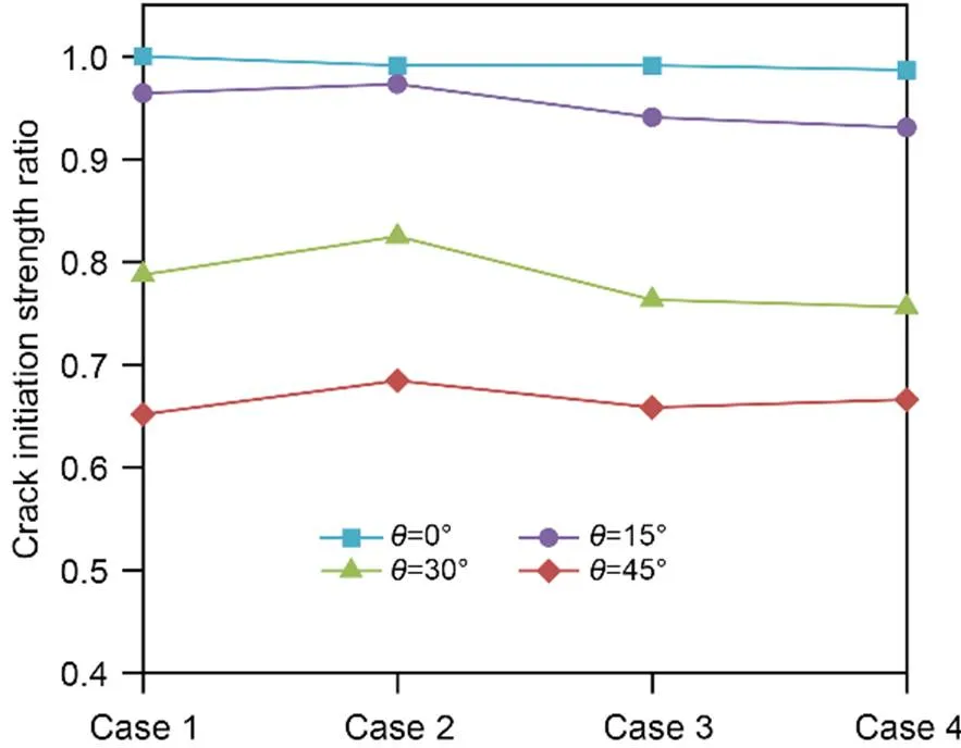
Fig. 7 Crack initiation strength normalized by the respective specimen strength of the disc specimens with different filled flaws (Cases 1–4)
The failure pattern analysis of the uniform distributed filling disc is demonstrated in Section S8 of the ESM.
4.2.2Non-uniform distributed filling material
In practical engineering, the distributions of flaw-fillings may not be uniform. To study the influences of non-uniform distributed fillings, in the case study of the Brazilian disc tests with filled flaws, the material property of fillings in one flaw is differentiated from that in another. The ratiosf1andf2are used here to describe the properties of the left and right fillings, respectively. The mean and variance off1andf2are adopted to express the degrees of non-uniformity of the filling distribution in the disc specimens. Table 5 shows the ratio of the fillings' tensile strength to cohesion in different cases.
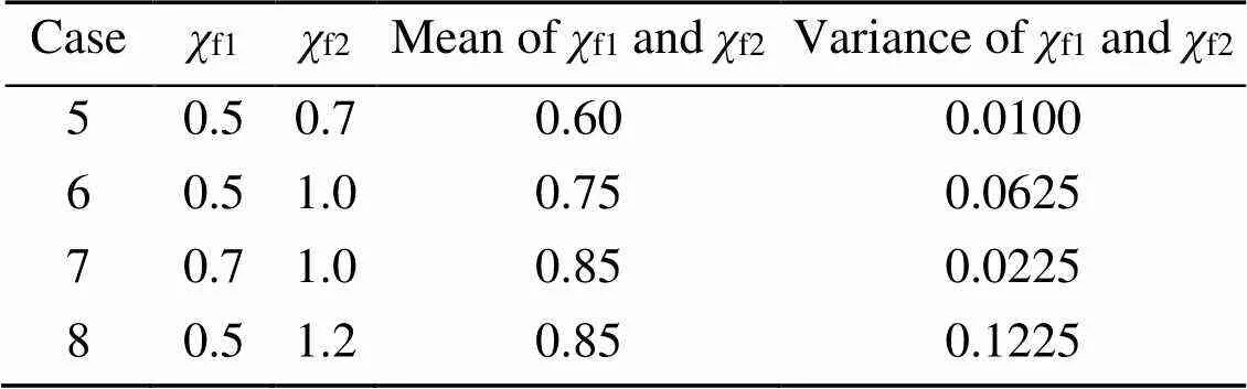
Table 5 Ratio of fillings' tensile strength to cohesion in different cases
4.2.2.1Fracture mechanism evolutions
To assess the influence of the fillings on the failure process of a nearby area, the disc is divided into two parts, parts A and B, as displayed in Fig. 8a. Fig. 8a is the evolutions of damage ratios in a typical case (=30°, Case 5). The characteristic incremental rates of damage ratio Δ/Δof parts A and B of four-disc specimens (=30°) are shown in Figs. 8b–8d.f1of the left flaw-fillings is 0.5, andf2of the right flaw-fillings is 0.5 to 1.2 in four different cases, namely, Cases 1, 5, 6, and 8. The variance off1andf2in the four cases gradually increases, indicating that the non-uniformity of filling distribution of the four cases increases with the increment of case number. Δis the period of 24.56 ms after peak load, which is denoted in Fig. 8a. The incremental rate of the tensile damage ratio is the largest in the case of uniform fillings (Case 1), and with the decrease of fillings strength in part B, the incremental rates of tensile and the shear damage ratio in part B decrease after the peak load. Nevertheless, the effect of tensile damage is predominant. The variation trend of shear damage ratio incremental rate of part A is consistent with that of the mixed-mode damage ratio incremental rate of part B. No mixed-mode damage is generated in part A. It can be seen that the change of the filling material can not only influence the various failure mechanism evolutions in nearby areas, but also influence the shear failure mechanism evolutions in distant areas.
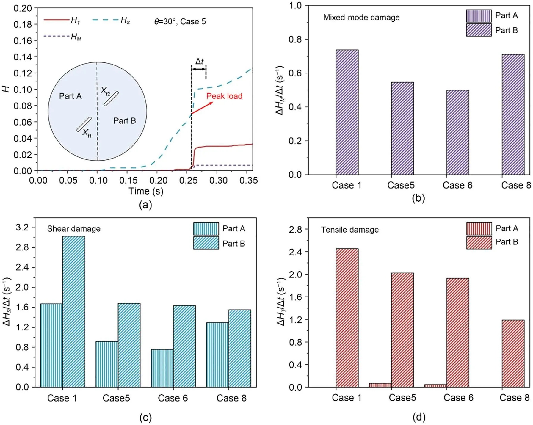
Fig. 8 Evolutions of damage ratios H of the disc specimen (θ=30°, Case 5) and a schematic diagram of the disc divided into two parts (a), and comparisons of damage ratio incremental rates of the disc specimens on the left and right sides: (b) mixed-mode damage; (c) shear damage; (d) tensile damage
To further analyze the influence of the non-uniform distributed filling material and its coupled effect with the flaw inclination angle on the failure mechanisms in progressive failure, the proportions of tensile damage, shear damage, and mixed-mode damage to the total number of damaged particles in the disc specimens represented by′,′, and′ versus flaw inclination angle are described in Fig. S10 of the ESM. Four cases (Cases 5–8) are given, in which the decreasing mean value off1andf2represents the weakening of filling strength, and the increasing variance value off1andf2denotes the increasing effect of the non-uniform distribution of the fillings.
According to Fig. S10a of the ESM, with the increase of flaw inclination angle,′ increases and′ decreases at peak load. The variation trend of′ or′ with flaw inclination angle is the same for different cases. In addition, Case 8 has the largest′, followed by Case 6, indicating that as the differences between the two flaw-fillings are bigger, the tensile damage accounted for a greater portion under peak load.′ is usually below 1.6% and is almost 0 when≤15°.
In the post-failure state (24.56 ms after peak load), for the same flaw inclination angle, the differences between the results of different cases are small, as demonstrated in Fig. S10b of the ESM. Only in Case 6 (=45°), is′ relatively high and′ relatively low.′ decreases with the increase of flaw inclination angle. The rate of increase of′ is high when≤15° and is low when≥30°.
The analysis above illustrates that non-uniform fillings have a certain influence on the failure state in the disc specimens. At peak load, when the fillings' non-uniform distribution becomes more obvious, the tensile damage takes a greater part in the evolution of the failure mechanism. The non-uniform distribution effect of the fillings is the largest whenis close to 45°. However, after peak load, the non-uniform fillings have negligible influence on the overall failure state, indicating that after peak load, the distribution of different types of failures tends to be stable and is similar for different cases.
4.2.2.2Mechanical responses and failure patterns
Fig. 9 shows the crack initiation strength normalized by the respective specimen strength versus different cases. Under the same flaw inclination angle, the differences between the cases off1≠f2and the cases off1=f2are less than 9%. It illustrates that non-uniform distributed fillings have little influence on bearing capacity. In Fig. 9, the crack initial strength ratio is almost 1 at=0°, showing that non-uniform fillings have little influence on the disc specimens at=0°. With the increase of flaw inclination angle, the ratio decreases gradually. For all the disc specimens with the same flaw inclination angle, the lowest crack initial strength ratio is obtained in Case 8 (f1=0.5,f2=1.2). This reflects that the disc specimen will exhibit more ductility when the fillings' strength is weaker and its distribution less uniform. That is consistent with the analysis in Section 4.2.2.1 of the evolution of the failure mechanism. In conclusion, the strength difference between the left and right sides of fillers influences the fracture mechanism evolutions in the failure process, and further alters the mechanical performance of the disc specimen.
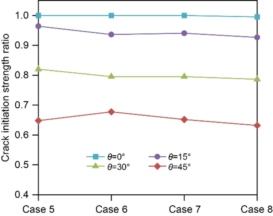
Fig. 9 Crack initiation strength normalized by the respective specimen strength of the disc specimens with different filled flaws (Cases 5–8)
The failure pattern analysis of the non-uniform distributed filling disc is demonstrated in Section S9 of the ESM.
5 Conclusions
In this study, the SPH method has been used to simulate the mixed-mode fracture of rock-like disc specimens. The fracture mechanism evolutions of the filled or unfilled flawed disc cases are analyzed. The main conclusions are as follows:
(1) As a mesh-less method, SPH is not confined by meshes, which makes it possible to simulate and analyze the fracture behavior of rocks. To distinguish the effects of tensile failure and shear failure, two damage variables are used to represent the two damage types. The numerical results from the Brazilian disc test with flaws demonstrate that the SPH approach proposed in this study has potentials for simulating rock fracture and can be the foundation of analysis of the heterogeneity of rocks.
(2) The coupled effect of disc material type and flaw inclination angle on the mechanism evolutions of crack coalescence in the disc with unfilled flaws is analyzed. With the decrease of the flaw inclination angle, the crack coalescence mechanism in the rock bridge area will transform from tensile failure dominant to shear failure dominant. It is proved that the crack coalescence is mainly caused by shear failure, and fracture mechanism evolutions determine the final crack coalescence mode of the disc specimen.
(3) The coupled influence of different fillings and flaw inclination angles of the flaw-filled disc is studied through the analysis of failure mechanism evolution. The incremental rate of tensile-activated damage in the failure mechanism evolution process affects the mechanical performance of the disc specimen. When the disc and filling have a similar ratio of tensile strength to cohesion, the tensile-activated damage increases rapidly, which makes the mechanical performance of the specimen more brittle. The filling material has a certain influence on the proportions of different failure mechanisms in the disc specimens, which may change the overall distribution of cracks in some cases. That influence becomes greater with the decrease of fillings' strength when the flaw inclination angle is approaching 45°.
(4) The coupled effect of non-uniform distributed fillings and flaw inclination angle on the failure mechanism evolutions of the flaw-filled disc is studied. The non-uniform distribution of the fillings can not only influence the failure mechanism evolution in the nearby area, but also influence the shear failure mechanism evolution in distant areas. The incremental rate of tensile damage in the failure mechanism evolution determines the mechanical response of the disc specimen. With the increasing non-uniformity of fillings' distribution, the incremental rate of tensile-activated damage drops after the peak load, and the disc specimen becomes more ductile. Non-uniform distributed fillings influence the final failure mechanisms, and the influence becomes more significant when the flaw inclination angle is close to 45° at peak load, which makes the disc specimen cracking paths more complex.
(5) It should be noted that the particle spacing is relatively large to simulate the cracking behavior of the fillings. To study the characteristics of filling fracture growth and fracture modes, the spatial discretization of the model should be further refined and rock heterogeneity parameters should be introduced. In future study, the fracture characteristics of the fillings can be studied using the SPH approach. Also, the stress intensity factor of cracks at different flaw angles and fillings in SPH simulation will be studied in the future to expand the application of the SPH method in fracture mechanics.
Acknowledgments
This work is supported in part by the National Natural Science Foundation of China (No. 51779084).
Author contributions
Tian WANG and Jian WANG designed the research. Tian WANG and Jiahe ZHANG processed the corresponding data. Tian WANG wrote the first draft of the manuscript. Sheng JIANG helped to organize the manuscript. Jian WANG and Sheng JIANG revised and edited the final version.
Conflict of interest
Tian WANG, Jian WANG, Sheng JIANG, and Jiahe ZHANG declare that they have no known competing financial interests or personal relationships that could have appeared to influence the work reported in this paper.
Electronic supplementary materials
Sections S1–S9; Eqs. (S1)–(S13); Figs. S1–S11
Adachi J, Siebrits E, Peirce A, et al., 2007. Computer simulation of hydraulic fractures. International Journal of Rock Mechanics and Mining Sciences, 44(5):739-757. https://doi.org/10.1016/j.ijrmms.2006.11.006
Afolagboye LO, He JM, Wang SJ, 2018. Crack initiation and coalescence behavior of two non-parallel flaws. Geotechnical and Geological Engineering, 36(1):105-133. https://doi.org/10.1007/s10706-017-0310-0
Benz W, Asphaug E, 1995. Simulations of brittle solids using smooth particle hydrodynamics. Computer Physics Communications, 87(1-2):253-265. https://doi.org/10.1016/0010-4655(94)00176-3
Bui HH, Fukagawa R, Sako K, et al., 2008. Lagrangian meshfree particles method (SPH) for large deformation and failure flows of geomaterial using elastic-plastic soil constitutive model. International Journal for Numerical and Analytical Methods in Geomechanics, 32(12):1537-1570. https://doi.org/10.1002/nag.688
Cai M, Kaiser PK, Tasaka Y, et al., 2004. Generalized crack initiation and crack damage stress thresholds of brittle rock masses near underground excavations. International Journal of Rock Mechanics and Mining Sciences, 41(5):833-847. https://doi.org/10.1016/j.ijrmms.2004.02.001
Chen JK, Beraun JE, Carney TC, 1999. A corrective smoothed particle method for boundary value problems in heat conduction. International Journal for Numerical Methods in Engineering, 46(2):231-252. https://doi.org/10.1002/(SICI)1097-0207(19990920)46:2<231::AID-NME672>3.0.CO;2-K
Chen WF, Mizuno E, 1990. Nonlinear Analysis in Soil Mechanics: Theory and Implementation. Elsevier, Amsterdam, the Netherlands.
Chen ZP, Shen LM, 2022. A modified smoothed particle hydrodynamics for modelling fluid-fracture interaction at mesoscale. Computational Particle Mechanics, 9(2):277-297. https://doi.org/10.1007/s40571-021-00409-x
Cleary PW, 1998. Modelling confined multi-material heat and mass flows using SPH. Applied Mathematical Modelling, 22(12):981-993. https://doi.org/10.1016/S0307-904X(98)10031-8
Das R, Cleary PW, 2010. Effect of rock shapes on brittle fracture using smoothed particle hydrodynamics. Theoretical and Applied Fracture Mechanics, 53(1):47-60. https://doi.org/10.1016/j.tafmec.2009.12.004
Das R, Cleary PW, 2015. Evaluation of accuracy and stability of the classical SPH method under uniaxial compression. Journal of Scientific Computing, 64(3):858-897. https://doi.org/10.1007/s10915-014-9948-4
Das R, Zhang Y, Schaubs P, et al., 2014. Modelling rock fracturing caused by magma intrusion using the smoothed particle hydrodynamics method. Computational Geosciences, 18(6):927-947. https://doi.org/10.1007/s10596-014-9437-8
Deb D, Pramanik R, 2013. Failure process of brittle rock using smoothed particle hydrodynamics. Journal of Engineering Mechanics, 139(11):1551-1565. https://doi.org/10.1061/(asce)em.1943-7889.0000592
Douillet-Grellier T, Jones BD, Pramanik R, et al., 2016. Mixed-mode fracture modeling with smoothed particle hydrodynamics. Computers and Geotechnics, 79:73-85. https://doi.org/10.1016/j.compgeo.2016.06.002
Douillet-Grellier T, Pramanik R, Pan K, et al., 2017. Development of stress boundary conditions in smoothed particle hydrodynamics (SPH) for the modeling of solids deformation. Computational Particle Mechanics, 4(4):451-471. https://doi.org/10.1007/s40571-016-0137-0
Gingold RA, Monaghan JJ, 1977. Smoothed particle hydrodynamics: theory and application to non-spherical stars. Monthly Notices of the Royal Astronomical Society, 181(3):375-389. https://doi.org/10.1093/mnras/181.3.375
Gui Y, Bui HH, Kodikara J, 2015. An application of a cohesive fracture model combining compression, tension and shear in soft rocks. Computers and Geotechnics, 66:142-157. https://doi.org/10.1016/j.compgeo.2015.01.018
Haeri H, Shahriar K, Marji MF, et al., 2014. Experimental and numerical study of crack propagation and coalescence in pre-cracked rock-like disks. International Journal of Rock Mechanics and Mining Sciences, 67:20-28. https://doi.org/10.1016/j.ijrmms.2014.01.008
Ichikawa Y, Kawamura K, Uesugi K, et al., 2001. Micro- and macrobehavior of granitic rock: observations and viscoelastic homogenization analysis. Computer Methods in Applied Mechanics and Engineering, 191(1-2):47-72. https://doi.org/10.1016/S0045-7825(01)00244-4
Jin Z, Lu Z, Yang Y, 2021. Numerical analysis of column collapse by smoothed particle hydrodynamics with an advanced critical state-based model. Journal of Zhejiang University-SCIENCE A (Applied Physics & Engineering), 22(11):882-893. https://doi.org/10.1631/jzus.A2000598
Lei RD, Zhang ZY, Berto F, et al., 2020. Cracking process and acoustic emission characteristics of sandstone with two parallel filled-flaws under biaxial compression. Engineering Fracture Mechanics, 237:107253. https://doi.org/10.1016/j.engfracmech.2020.107253
Libersky LD, Petschek AG, Carney TC, et al., 1993. High strain Lagrangian hydrodynamics: a three-dimensional SPH code for dynamic material response. Journal of Computational Physics, 109(1):67-75. https://doi.org/10.1006/jcph.1993.1199
Lin P, Wong RHC, Tang CA, 2015. Experimental study of coalescence mechanisms and failure under uniaxial compression of granite containing multiple holes. International Journal of Rock Mechanics and Mining Sciences, 77:313-327. https://doi.org/10.1016/j.ijrmms.2015.04.017
Lucy LB, 1977. A numerical approach to the testing of the fission hypothesis. Astronomical Journal, 82:1013-1024. https://doi.org/10.1086/112164
Ma G, Zhang YD, Zhou W, et al., 2018. The effect of different fracture mechanisms on impact fragmentation of brittle heterogeneous solid. International Journal of Impact Engineering, 113:132-143. https://doi.org/10.1016/j.ijimpeng.2017.11.016
Miao ST, Pan PZ, Wu ZH, et al., 2018. Fracture analysis of sandstone with a single filled flaw under uniaxial compression. Engineering Fracture Mechanics, 204:319-343. https://doi.org/10.1016/j.engfracmech.2018.10.009
Monaghan JJ, 1992. Smoothed particle hydrodynamics. Annual Review of Astronomy and Astrophysics, 30(1):543-574. https://doi.org/10.1146/annurev.aa.30.090192.002551
Pal S, Kaynia AM, Bhasin RK, et al., 2012. Earthquake stability analysis of rock slopes: a case study. Rock Mechanics and Rock Engineering, 45(2):205-215. https://doi.org/10.1007/s00603-011-0145-6
Pan PZ, Miao ST, Jiang Q, et al., 2020. The influence of infilling conditions on flaw surface relative displacement induced cracking behavior in hard rock. Rock Mechanics and Rock Engineering, 53(10):4449-4470. https://doi.org/10.1007/s00603-019-02033-x
Potapov S, Maurel B, Combescure A, et al., 2009. Modeling accidental-type fluid-structure interaction problems with the SPH method. Computers & Structures, 87(11-12):721-734. https://doi.org/10.1016/j.compstruc.2008.09.009
Sharafisafa M, Nazem M, 2014. Application of the distinct element method and the extended finite element method in modelling cracks and coalescence in brittle materials. Computational Materials Science, 91:102-121. https://doi.org/10.1016/j.commatsci.2014.04.006
Sharafisafa M, Shen LM, Xu QF, 2018. Characterisation of mechanical behaviour of 3D printed rock-like material with digital image correlation. International Journal of Rock Mechanics and Mining Sciences, 112:122-138. https://doi.org/10.1016/j.ijrmms.2018.10.012
Sharafisafa M, Shen LM, Zheng YG, et al., 2019. The effect of flaw filling material on the compressive behaviour of 3D printed rock-like discs. International Journal of Rock Mechanics and Mining Sciences, 117:105-117. https://doi.org/10.1016/j.ijrmms.2019.03.031
Shen BT, Stephansson O, Einstein HH, et al., 1995. Coalescence of fractures under shear stresses in experiments. Journal of Geophysical Research: Solid Earth, 100(B4):5975-5990. https://doi.org/10.1029/95JB00040
Tang CA, Lin P, Wong RHC, et al., 2001. Analysis of crack coalescence in rock-like materials containing three flaws—part II: numerical approach. International Journal of Rock Mechanics and Mining Sciences, 38(7):925-939. https://doi.org/10.1016/S1365-1609(01)00065-X
Tian WL, Yang SQ, 2017. Experimental and numerical study on the fracture coalescence behavior of rock-like materials containing two non-coplanar filled fissures under uniaxial compression. Geomechanics and Engineering, 12(3):541-560. https://doi.org/10.12989/gae.2017.12.3.541
Wang J, Chan D, 2014. Frictional contact algorithms in SPH for the simulation of soil-structure interaction. International Journal for Numerical and Analytical Methods in Geomechanics, 38(7):747-770. https://doi.org/10.1002/nag.2233
Wang J, Wu H, Gu CS, et al., 2013. Simulating frictional contact in smoothed particle hydrodynamics. Science China Technological Sciences, 56(7):1779-1789. https://doi.org/10.1007/s11431-013-5262-x
Wang T, Wang J, Zhang P, 2020. An improved support domain model of smoothed particle hydrodynamics method to simulate crack propagation in materials. International Journal of Computational Methods, 17(10):1950081. https://doi.org/10.1142/S0219876219500816
Wang YN, Bui HH, Nguyen GD, et al., 2019. A new SPH-based continuum framework with an embedded fracture process zone for modelling rock fracture. International Journal of Solids and Structures, 159:40-57. https://doi.org/10.1016/j.ijsolstr.2018.09.019
Wang YN, Tran HT, Nguyen GD, et al., 2020. Simulation of mixed-mode fracture using SPH particles with an embedded fracture process zone. International Journal for Numerical and Analytical Methods in Geomechanics, 44(10):1417-1445. https://doi.org/10.1002/nag.3069
Whyatt JK, Board MP, 1991. Numerical Exploration of Shear-Fracture-Related Rock Bursts Using a Strain-Softening Constitutive Law. US Department of the Interior, Bureau of Mines, USA, p.1-20.
Wong LNY, Einstein HH, 2009a. Crack coalescence in molded gypsum and Carrara marble: part 1. Macroscopic observations and interpretation. Rock Mechanics and Rock Engineering, 42(3):475-511. https://doi.org/10.1007/s00603-008-0002-4
Wong LNY, Einstein HH, 2009b. Systematic evaluation of cracking behavior in specimens containing single flaws under uniaxial compression. International Journal of Rock Mechanics and Mining Sciences, 46(2):239-249. https://doi.org/10.1016/j.ijrmms.2008.03.006
Wong RHC, Chau KT, 1998. Crack coalescence in a rock-like material containing two cracks. International Journal of Rock Mechanics and Mining Sciences, 35(2):147-164. https://doi.org/10.1016/S0148-9062(97)00303-3
Wong RHC, Lin P, Chau KT, et al., 2000. The effects of confining compression on fracture coalesence in rock-like material. Key Engineering Materials, 183-187:857-862. https://doi.org/10.4028/www.scientific.net/kem.183-187.857
Xu Y, Chen SH, 2016. A method for modeling the damage behavior of concrete with a three-phase mesostructure. Construction and Building Materials, 102:26-38. https://doi.org/10.1016/j.conbuildmat.2015.10.151
Yeylaghi S, Moa B, Buckham B, et al., 2017. ISPH modelling of landslide generated waves for rigid and deformable slides in Newtonian and non-Newtonian reservoir fluids. Advances in Water Resources, 107:212-232. https://doi.org/10.1016/j.advwatres.2017.06.013
Yin ZY, Jin YF, Zhang X, 2021. Large deformation analysis in geohazards and geotechnics. Journal of Zhejiang University-SCIENCE A (Applied Physics & Engineering), 22(11):851-855. https://doi.org/10.1631/jzus.A21LDGG1
Yu J, Chen SJ, Chen X, et al., 2015. Experimental investigation on mechanical properties and permeability evolution of red sandstone after heat treatments. Journal of Zhejiang University-SCIENCE A (Applied Physics & Engineering), 16(9):749-759. https://doi.org/10.1631/jzus.A1400362
Zhang XP, Wong LNY, 2012. Cracking processes in rock-like material containing a single flaw under uniaxial compression: a numerical study based on parallel bonded-particle model approach. Rock Mechanics and Rock Engineering, 45(5):711-737. https://doi.org/10.1007/s00603-011-0176-z
Zhang XP, Wong LNY, Wang SJ, 2015. Effects of the ratio of flaw size to specimen size on cracking behavior. Bulletin of Engineering Geology and the Environment, 74(1):181-193. https://doi.org/10.1007/s10064-014-0596-6
Zhao YL, Zhang LY, Wang WJ, et al., 2016. Cracking and stress–strain behavior of rock-like material containing two flaws under uniaxial compression. Rock Mechanics and Rock Engineering, 49(7):2665-2687. https://doi.org/10.1007/s00603-016-0932-1
Zhao ZH, Zhou D, 2016. Mechanical properties and failure modes of rock samples with grout-infilled flaws: a particle mechanics modeling. Journal of Natural Gas Science and Engineering, 34:702-715. https://doi.org/10.1016/j.jngse.2016.07.022
Zhao ZH, Lin T, Chen YD, et al., 2022. Shear behaviors of natural rock fractures infilled with cemented calcite. Computers and Geotechnics, 141:104493. https://doi.org/10.1016/j.compgeo.2021.104493
Zheng G, Zhu R, Sun JB, et al., 2021. Numerical study on failure propagation between two closely spaced tunnels. Journal of Zhejiang University-SCIENCE A (Applied Physics & Engineering), 22(11):894-908. https://doi.org/10.1631/jzus.A2000502
Zhou XP, Cheng H, Feng YF, 2014. An experimental study of crack coalescence behaviour in rock-like materials containing multiple flaws under uniaxial compression. Rock Mechanics and Rock Engineering, 47(6):1961-1986. https://doi.org/10.1007/s00603-013-0511-7
May 2, 2022; Revision accepted Aug. 1, 2022;
https://doi.org/10.1631/jzus.A2200238
Jian WANG, https://orcid.org/0000-0001-7833-3217
Crosschecked Nov. 24, 2022
© Zhejiang University Press 2023
 Journal of Zhejiang University-Science A(Applied Physics & Engineering)2023年1期
- Journal of Zhejiang University-Science A(Applied Physics & Engineering)的其它文章
- Multiscale multiphysics modeling in geotechnical engineering
- CFD-DEM modelling of suffusion in multi-layer soils with different fines contents and impermeable zones
- Effect of hydraulic fracture deformation hysteresis on CO2 huff-n-puff performance in shale gas reservoirs
- Finite volume method-based numerical simulation method for hydraulic fracture initiation in rock around a perforation
- Mechanistic investigation on Hg0 capture over MnOx adsorbents: effects of the synthesis methods
- Modelling and applications of dissolution of rocks in geoengineering