
Effect of hydraulic fracture deformation hysteresis on CO2 huff-n-puff performance in shale gas reservoirs
2023-02-06 07:02XiaYANPiyangLIUZhaoqinHUANGHaiSUNKaiZHANGJunfengWANGJunYAO
Xia YAN, Pi-yang LIU, Zhao-qin HUANG, Hai SUN, Kai ZHANG,, Jun-feng WANG, Jun YAO*
Research Article
Effect of hydraulic fracture deformation hysteresis on CO2huff-n-puff performance in shale gas reservoirs
Xia YAN1, Pi-yang LIU2, Zhao-qin HUANG1, Hai SUN1, Kai ZHANG1,2, Jun-feng WANG3, Jun YAO1*
1School of Petroleum Engineering, China University of Petroleum (East China), Qingdao 266580, China2Civil Engineering School, Qingdao University of Technology, Qingdao 266520, China3Chuandong Drilling Company, CNPC Chuanqing Drilling Engineering Company Limited, Chongqing 401120, China
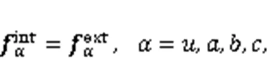
As a promising enhanced gas recovery technique, CO2huff-n-puff has attracted great attention recently. However, hydraulic fracture deformation hysteresis is rarely considered, and its effect on CO2huff-n-puff performance is not well understood. In this study, we present a fully coupled multi-component flow and geomechanics model for simulating CO2huff-n-puff in shale gas reservoirs considering hydraulic fracture deformation hysteresis. Specifically, a shale gas reservoir after hydraulic fracturing is modeled using an efficient hybrid model incorporating an embedded discrete fracture model (EDFM), multiple porosity model, and single porosity model. In flow equations, Fick’s law, extended Langmuir isotherms, and the Peng-Robinson equation of state are used to describe the molecular diffusion, multi-component adsorption, and gas properties, respectively. In relation to geomechanics, a path-dependent constitutive law is applied for the hydraulic fracture deformation hysteresis. The finite volume method (FVM) and the stabilized extended finite element method (XFEM) are applied to discretize the flow and geomechanics equations, respectively. We then solve the coupled model using the fixed-stress split iterative method. Finally, we verify the presented method using several numerical examples, and apply it to investigate the effect of hydraulic fracture deformation hysteresis on CO2huff-n-puff performance in a 3D shale gas reservoir. Numerical results show that hydraulic fracture deformation hysteresis has some negative effects on CO2huff-n-puff performance. The effects are sensitive to the initial conductivity of hydraulic fracture, production pressure, starting time of huff-n-puff, injection pressure, and huff-n-puff cycle number.
Enhanced gas recovery; CO2huff-n-puff; Coupled geomechanics and multi-component flow; Hydraulic fracture deformation hysteresis; Embedded discrete fracture model (EDFM)
1 Introduction
In recent years, the development of shale gas has received great attention all over the world (Striolo and Cole, 2017; Sun et al., 2017; Yan et al., 2018b; Wang et al., 2019; Liu et al., 2020a). Typically, a shale gas reservoir has extremely small pores and ultralow matrix permeability (Song et al., 2016; Fan et al., 2019). Nevertheless, economic exploitation of shale gas has been achieved by horizontal drilling (Giger et al., 1984; Karlsson et al., 1991) and artificial fracturing (Hubbert and Willis, 1957; Zeng et al., 2018, 2019). Field data show a rapid decline in productivity after a period of production (Hasan et al., 2017; Li and Elsworth, 2019). Therefore, some advanced techniques, such as gas injection (Godec et al., 2014), infill drilling (Urban et al., 2016), and refracturing (Shah et al., 2017) have been proposed to enhance gas recovery. CO2huff-n-puff (cyclic injection) is regarded as promising, as it could be one of the most effective techniques to enhance gas recovery from reservoirs with ultralow permeability (Zuloaga et al., 2017; Du and Nojabaei, 2019). Moreover, it could also contribute to CO2sequestration (Kim et al., 2017).
Although commercialization of CO2huff-n-puff has not yet been realized, many numerical studies have been carried out that show the feasibility and efficiency of this technique. Fathi and Akkutlu (2014) improved CO2huff-n-puff performance by using a triple-porosity single-permeability model. Their numerical results showed that competitive adsorption and counter-diffusion are important to CH4recovery and CO2sequestration. Similarly, Xu et al. (2017) developed a triple-porosity dual-permeability model, in which competitive adsorption and binary diffusion are considered, to investigate the feasibility of CO2huff-n-puff in shale gas reservoirs. Kim et al. (2017) developed a coupled model considering molecular diffusion, competitive adsorption, CO2dissolution, and stress-dependent permeability. They used this model to carry out sensitivity analyses of CO2huff-n-puff and CO2flooding. Huang et al. (2020) evaluated the effect of kerogen distribution on different CO2injection schemes in shale gas reservoirs. These studies have demonstrated the feasibility and efficiency of CO2huff-n-puff in shale gas reservoirs, and identified some of the factors influencing this technology. Nevertheless, most studies focused only on fluid flow, and the effects of geomechanics were not examined comprehensively. Geomechanical effects are expected to affect CO2huff-n-puff significantly (Gala and Sharma, 2018), as the cyclic production/injection process during huff-n-puff can be considered as several loading/unloading periods (Liu et al., 2020b). In this context, deformation hysteresis (i.e., irreversible deformation) of hydraulic fracture could occur during CO2huff-n-puff (Ye et al., 2012; Ghanizadeh et al., 2016; Li et al., 2017), which would affect fracture properties and well production. The conventional simplification of the geomechanical effects considers only the pressure-dependent permeability and is insufficient to accurately model fracture deformation (Yan et al., 2020). Therefore, hydraulic fracture deformation hysteresis and its effect on CO2huff-n-puff performance should be simulated and investigated through a hydro-mechanical coupling model that comprehensively incorporates geomechanical effects. On the other hand, CO2injection may induce temperature changes because of cold-CO2injection and the Joule-Thomson phenomenon. These thermal effects also affect aspects of production and injection performance, such as geothermal energy extraction combined with CO2storage (Mahmoodpour et al., 2022a, 2022b).
A complex fracture system containing a small amount of hydraulic fractures and numerous natural fractures could be created in a shale reservoir through artificial fracturing (Yan et al., 2018b). As weak surfaces and main flow channels, these fractures are extremely stress-sensitive and have an important influence on fluid flow (Liu et al., 2020a). To investigate the effect of fractures on fluid flow in deformed shale reservoirs, researchers have proposed many numerical models, such as the equivalent continuum model (Liu J et al., 2019), multiple porosity model (Pruess, 1991; Kim and Moridis, 2014; Yu and Sepehrnoori, 2014; Zhang and Borja, 2021; Zhang et al., 2021, 2022), discrete fracture model (Garipov et al., 2016; Norbeck et al., 2016; Jiang and Yang, 2018), and a hybrid model (Ren et al., 2016; Yan et al., 2018a, 2018b). Among these models, the hybrid model, in which hydraulic fractures are represented explicitly and natural fractures implicitly, has been the most promising. However, hydraulic fracture deformation hysteresis has not been considered in the hybrid models; therefore, they cannot be applied directly to study how hydraulic fracture deformation hysteresis affects CO2huff-n-puff performance in shale gas reservoirs.
In this study, a novel hydro-mechanical coupling model is presented to evaluate CO2huff-n-puff performance in shale gas reservoirs considering hydraulic fracture deformation hysteresis. Specifically, a fractured shale gas reservoir is modeled using an efficient hybrid model consisting of an embedded discrete fracture model (EDFM) (Moinfar et al., 2012; Yan et al., 2016), multiple porosity model, and single porosity model. In the flow model, we consider the viscous flow, molecular diffusion, Knudsen diffusion, and multi-component adsorption, and adopt the Peng-Robinson equation of state (Jiang et al., 2014), extended Langmuir isotherms (Liu LJ et al., 2019), and Fick's law (Webb and Pruess, 2003). In the geomechanics model, a path-dependent constitutive law is applied for hydraulic fracture deformation hysteresis. For numerical discretization, we use the finite volume method (FVM) (Versteeg and Malalasekera, 1995; Zhu et al., 2019; Qiu et al., 2020) to discretize the flow model, and stabilized extended finite element method (XFEM) (Yan et al., 2018b) to discretize the geomechanics model. We solve the coupled model by means of the fixed-stress split iterative method (Kim et al., 2012). Finally, we verify the proposed method, and then use it to investigate how hydraulic fracture deformation hysteresis affects CO2huff-n-puff performance in a 3D shale gas reservoir.
This paper is structured as follows: the coupled multi-component flow and geomechanics model are presented in Section 2, and its numerical solution in Section 3. Numerical examples used to test the proposed method and study the effect of hydraulic fracture deformation hysteresis on CO2huff-n-puff performance are presented in Section 4, and conclusions are summarized in Section 5.
2 Mathematical model
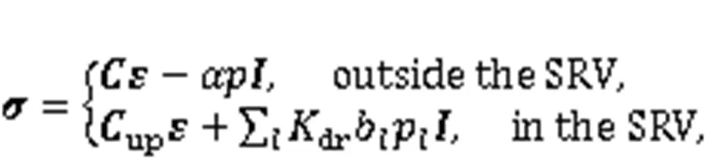
Fig. 1 is a sketch of a typical shale gas reservoir that includes two different regions: one is close to the hydraulic fractures, and contains a huge number of natural fractures. This region is usually named the stimulated reservoir volume (SRV). The other region outside of the SRV contains few natural fractures. Here, we apply an efficient hybrid model for the simulation of CO2huff-n-puff in such a shale gas reservoir. In this model, a single porosity model is applied to the part outside the SRV since only the shale matrix is of interest, and a multiple porosity model is adopted in the SRV for considering the shale matrix and natural fractures. The EDFM is used to explicitly represent hydraulic fractures and accurately consider hydraulic fracture deformation hysteresis.
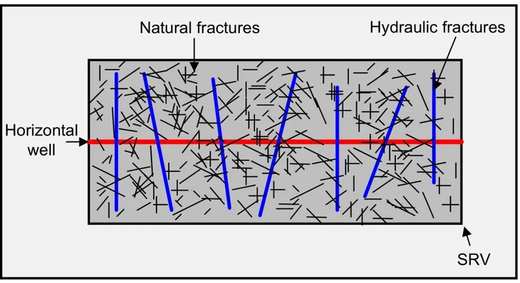
Fig. 1 Schematic diagram of a typical shale gas reservoir
2.1 Multi-component flow model
In this study, we assumed that the gas contains two components (i.e., CH4and CO2), and exists as adsorbed and free phases in the matrix, but only as free phase in the fractures. According to the mass conservation law (Wu et al., 2014), the isothermal single-phase multi-component flow satisfies:
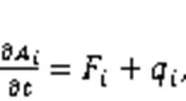
wheredenotes the time; the subscriptindicates the component index;,, andindicate the mass accumulation, mass flux, and source, respectively. The mass accumulation of componentis
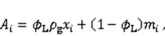
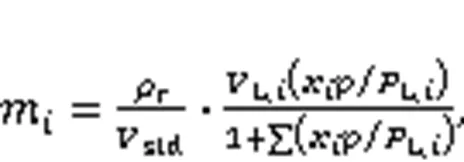
whereLis the Lagrange porosity that considers the geomechanical effect on porosity (Yan et al., 2018b);gis the gas molar density, which can be obtained from the Peng-Robinson equation of state (Jiang et al., 2014);xis the component molar fraction;mindicates the adsorbed molar of component, which can be calculated using the extended Langmuir isotherms (Liu LJ et al., 2019) as a function of gas pressure and the component molar fraction:

where the first and second items (right side) represent the mass flux caused by Darcy flow and molecular diffusion, respectively. Here, we assume that the molecular diffusion satisfies Fick's law (Webb and Pruess, 2003);is the gas velocity;eff,iis the effective diffusion coefficient, as defined by Liu LJ et al. (2019). According to Darcy's law, the gas velocity is
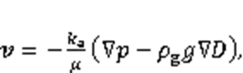
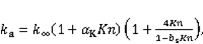
whereis the gas viscosity, which can be calculated using the Lohrenz-Bray-Clark method (Lohrenz et al., 1964);denotes the acceleration due to gravity;is the depth;aindicates the apparent gas permeability (Song et al., 2016; Fan et al., 2019; Liu LJ et al., 2019):
2.2 Geomechanics model
Assuming a quasi-static process, the linear mom entum balance equation for geomechanics is given as:
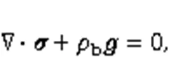
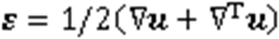
wherebdenotes the bulk density. Here, the sign convention of compressive stress being negative is adopted for internal force. The total stress tensorcan be defined as (Yan et al., 2018b)
A sketch of the geomechanic boundaries is shown in Fig. 2. We can mathematically express these boundary conditions as:
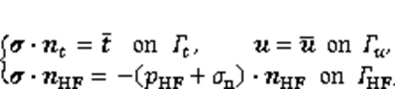
Fig. 2 Sketch of a fractured reservoir and its boundaries
2.3 Constitutive relations
The properties of the shale matrix, natural fracture, and hydraulic fracture are all stress-sensitive in shale reservoirs. Therefore, we need to specify these constitutive relations in terms of the stress explicitly or implicitly before simulating the CO2huff-n-puff process. The dynamic change in the matrix intrinsic permeabilitymis associated with the Lagrange porosityL, which is given by the Kozeny-Carman equation (Liu et al., 2011). In the multiple porosity model, the dynamic permeability of natural fractureffor each gridblock is given as a function of the volumetric strainv(Yan et al., 2018b). The expressions formandfare given in Section S1 of the ESM.
In this study, to consider the hysteresis effect on the deformation and permeability evolution of hydraulic fractures, the incremental forms for the stress‒strain relationship and stress‒permeability relationship are given by Li et al. (2017) and Liu et al. (2020b):
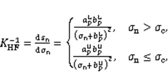

Now, the properties of hydraulic fracture are updated as:
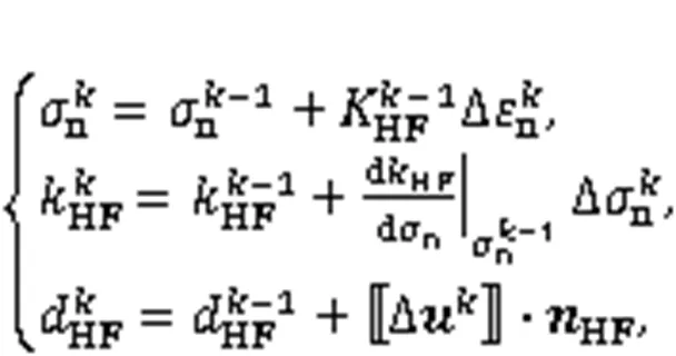
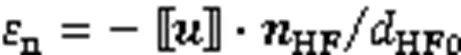
where the superscriptrepresents the calculation step, Δ indicates the increment, andHFis the hydraulic fracture aperture. Note that we consider only the normal deformation of a hydraulic fracture here.
3 Numerical schemes
In this section, we present a numerical method for the hydro-mechanical coupling model. As shown in Fig. 3, the reservoir region without hydraulic fractures is discretized using orthogonal grids, then hydraulic fractures are embedded into these grids. The nested grids for the multiple porosity model are constructed in the SRV region according to the improved multiple interacting continua (MINC) method (Yan et al., 2018b). After geometry discretization, the flow and geomechanics equations are discretized with the FVM and stabilized XFEM (S-XFEM), and the coupling model is iteratively solved via the fixed-stress split iterative method.
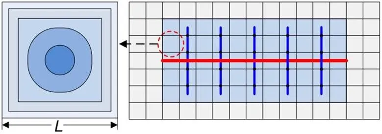
Fig. 3 Sketch of the geometry discretization (blue line: hydraulic fracture; red line: horizontal well). References to color refer to the online version of this figure
3.1 Flow equations discretization
Firstly, we apply the FVM for the discretization of Eq. (1), then write it in the residual form:
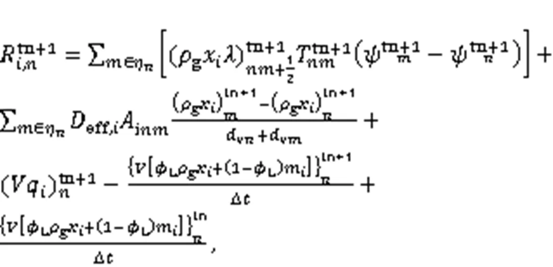

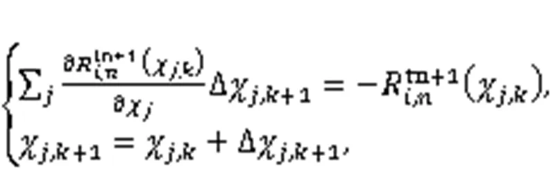
where subscriptsanddenote the index of primary variables and the iteration level, respectively;indicates the primary variables; Δrepresents primary variable increment.
3.2 Geomechanics equations discretization
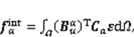
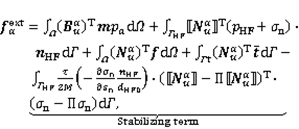
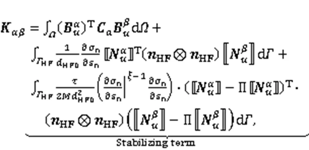
For discretization of the geomechanics equations, we first substitute Eqs. (8) and (9) into the weak form of Eq. (7), which is obtained based on virtual work theory (Zienkiewicz and Taylor, 2000). Equal-order linear interpolation is applied to approximate displacement in the XFEM. This does not satisfy the discrete Ladyzhenskaya–Babuska–Brezzi stability condition (Liu and Borja, 2010), and could result in displacement oscillation at hydraulic fractures (Yan et al., 2018b). To eliminate this oscillation, a stabilizing term based on the polynomial pressure projection technique (Liu and Borja, 2010) is added into the weak form:


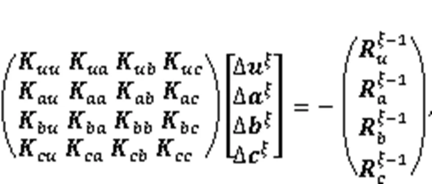
In this study, we add the Heaviside, fracture tip asymptotic, and junction enrichment functions to the standard finite element space (Khoei, 2014) for simulating the displacement discontinuity at hydraulic fractures. Then, the enriched displacement field and its test function are substituted into Eq. (15), and the necessity that Eq. (15) must keep for any kinematically admissible test function is considered. Eq. (15) is written as (more details can be seen in the Section S1 of the ESM)
with

3.3 Fixed-stress split iterative method
To solve the hydro-mechanical coupling model, the fixed-stress split iterative method is adopted here due to its stability and flexibility (Kim et al., 2012). As shown in Fig. 4, the flow model is first solved with the fixed stress, and then the geomechanics model is solved with the gas pressure obtained from the flow model. Within each time step, this iteration procedure is repeated until the solution converges to an allowable tolerance. In addition, we update the properties of the matrix and fracture according to the geomechanics results.

Fig. 4 Flow diagram of the fixed-stress split iterative method
4 Numerical examples
In this section, we work through a series of num erical examples. Firstly, we verify our codes of the multi-component model by comparison with the GEM of Computer Modelling Group (CMG, 2015), which is a commercial unconventional reservoir simulator. However, hydraulic fracture deformation hysteresis cannot be considered in CMG-GEM; then, we verify the S-XFEM iterative formulation for simulating hydraulic fracture deformation hysteresis by comparison with COMSOL Multiphysics (COMSOL, 1998), which is a multiphysics simulation software based on the finite element method. In COMSOL, fractures are explicitly represented using matching refined gridding, leading to high computational costs. Unlike COMSOL, our proposed approach can explicitly represent fractures with non-matching grids, thus the challenges associated with matching refined gridding are bypassed entirely. After that, a classical Terzaghi's consolidation problem (Jaeger et al., 2005) in porous media is introduced to verify the fixed-stress split iterative method. Finally, we work through some examples to study the effect of deformation hysteresis of hydraulic fracture on CO2huff-n-puff performance.
4.1 Model verification
4.1.1Multi-component model validation
To verify our codes of the multi-component model, a simple naturally fractured shale gas reservoir was modeled using our codes and CMG-GEM. As shown in Fig. 5, the reservoir size was 100 m×100 m×4 m, and it was assumed to be a dual-porosity single-permeability medium with the pseudo-steady inter-porosity flow. A vertical production well is set at the center of this reservoir and connects to natural fractures. The reservoir and its component properties (Vermylen, 2011) are given in Table 1. Fig. 6 shows the cumulative production and production rate of each component. The results from our codes and CMG-GEM show close agreement.
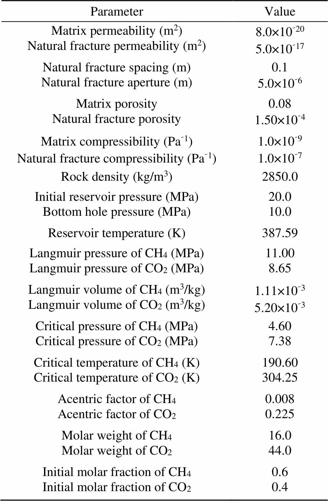
Table 1 Reservoir and its component properties for multi-component verification
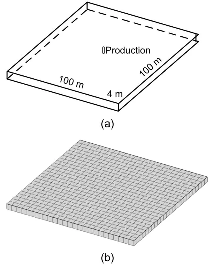
Fig. 5 Schematic of the reservoir (a) and its computational grids (25×25×1) (b)
4.1.2Hydraulic fracture deformation hysteresis
Fig. 7a shows a 3D model used to verify the S-XFEM formulation that was developed to simulate hydraulic fracture deformation hysteresis. This model is homogenous. Its Poisson's ratio is 0.2, and its Young's modulus is 1.0 GPa. We set a vertical fracture (1.68 m×1.68 m×0.005 m) at its center. Here, the constitutive model considering deformation hysteresis (i.e., Eq. (16)) was adopted, and the parametersL,L,U, andUwere set as 0.8415, 10.88, 0.5249, and 25.29 MPa, respectively. The top boundary was the traction-boundary with a uniform load increased (0 to 100 MPa) and then decreased (100 to 0 MPa) stepwise. The other boundaries were the fixed normal displacement boundary. A stress observation point (red point) was set at the fracture center, and two displacement observation lines (dotted lines,=1.0 m,=1.75 m) were set on the fracture. Then, the two different methods (i.e., COMSOL and the S-XFEM) were applied to simulate the mechanical problem. The gridding of COMSOL was refined, and its number was 56190. On the other hand, a uniform gridding (15×25×25) was applied to the S-XFEM. The computational times used by COMSOL and the S-XFEM were 18 s and 7 s, respectively. Figs. 7b and 7c show the–displacement fields of the two methods. It can be seen that these two fields are almost the same.
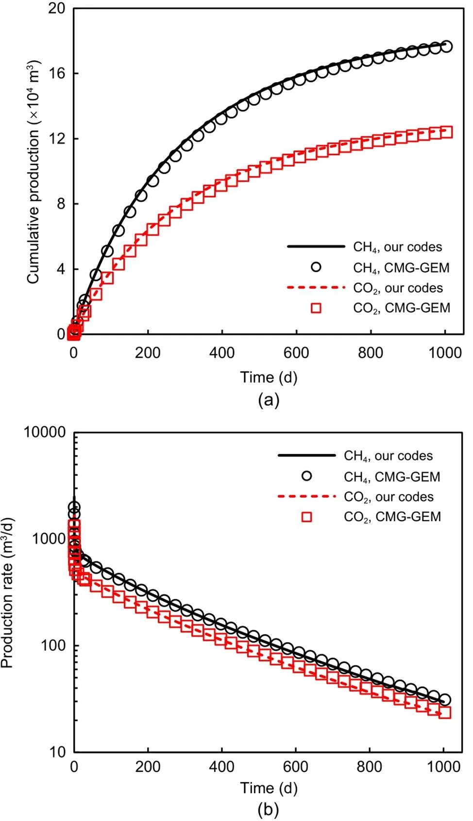
Fig. 6 Comparison of cumulative production (a) and production rate (b) for each component
Fig. 8a shows the residual fracture apertures of whole fracture after unloading obtained from COMSOL (black dots) and the S-XFEM (surface). The residual fracture apertures along two displacement observation lines obtained from the different methods are shown in Fig. 8b. The two methods show close agreement. In addition, another two cases with different cycle loads (0→25→0 MPa and 0→50→0 MPa) were carried out for comparison. Fig. 8c gives the stress–strain curves (the relationships between normal stress and normal strain) at the observation point for the three cases, which were obtained from the two methods. The results from S-XFEM and COMSOL are almost the same. Moreover, the significant deformation hysteresis (irrecoverable strain at no-load state) and nonlinear feature caused by the constitutive model considering deformation hysteresis can be seen.
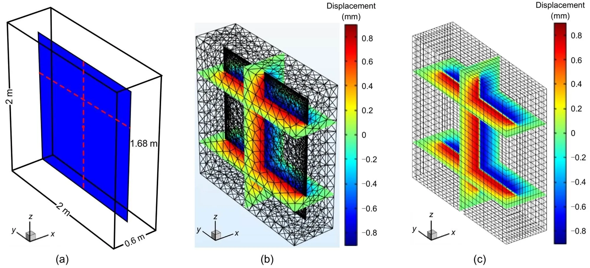
Fig. 7 Schematic of the fractured medium model (a) and x–displacement fields obtained from COMSOL (b) and the S-XFEM (c). References to color refer to the online version of this figure
4.1.3Terzaghi’s consolidation problem
Terzaghi's consolidation problem in porous media is introduced here to verify the fixed-stress split iterative method. The geometry model and boundary conditions are shown in Fig. 9a. The initial fluid pressure was 0 MPa. We applied a uniform constant load on the top and bottom boundaries, and maintained them throughout the consolidation process. The viscosity, density, and compressibility of fluid were 1 mPa·s, 1000 kg/m3, and 5×10⁻⁹Pa-1, respectively. The Poisson's ratio, Young's modulus, Biot coefficient, porosity, and permeability of matrix were 0.3, 1 GPa, 0.79, 0.3, and 1×10-13m2, respectively. We simulated this consolidation problem by using the fixed-stress split iterative method, and then compared the results with the analytical solutions (Jaeger et al., 2005). The fluid pressure comparison is shown in Fig. 9b, and the upper surface displacement comparison in Fig. 9c. They show excellent agreement. Note that we have plotted only the upper half of the pressure profile, due to its symmetry.
4.2 Application and discussion
In this subsection, we analyze some case studies to illustrate how hydraulic fracture deformation hysteresis affects the CO2huff-n-puff performance in fractured shale gas reservoirs. A 3D model of dimensions 700 m×340 m×30 m, including three layers (overburden, shale reservoir, and underburden), is shown in Fig. 10a. The height of each layer is 10 m, and the SRV region (dashed line) with five hydraulic fractures is 540 m×220 m×10 m. The spacing, height, and length of the hydraulic fractures are 100 m, 10 m, and 190 m, respectively. A horizontal well (red line) is set through the centers of hydraulic fractures, and the observation point (white point) is set at the center of the 3rd fracture. This reservoir is initially saturated with CH4. Its flow boundaries are closed. The right, back, and top geomechanics boundaries are the traction-boundary with uniform normal loads (45, 50, and 45 MPa, respectively), and the other boundaries are the fixed normal displacement boundary. The component properties can be obtained from Table 1, and the reservoir properties are given in Table 2 (Ryder, 1996; Yan et al., 2018b; Liu et al., 2020b). Note that the initial porosity of natural fractures is an equivalent porosity, which is the product of the intrinsic poro sity and volume fraction. The dynamic properties of the matrix and fractures presented in Section 2.3 are adopted here. Fig. 10b gives the computational grids. Note that the overburden and underburden in this model are used to improve consideration of geomechanical effects, and they are both impermeable. In other words, gas exists only in the reservoir part. For convenience, we have plotted only the reservoir part in the following analysis.
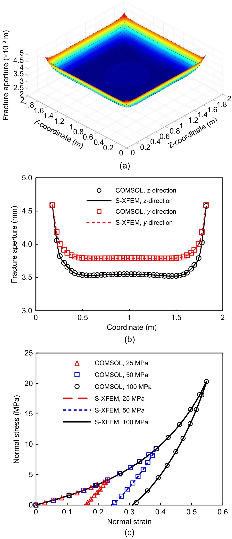
Fig. 8 Comparison of the residual fracture apertures of whole fracture (a) and along two displacement observation lines (b), and the stress–strain curves at the observation point (c). References to color refer to the online version of this figure
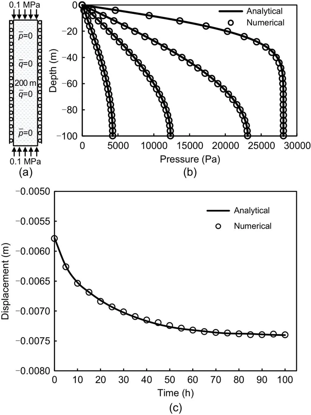
Fig. 9 Sketch of the consolidation model (a) and its pressure comparison (b), and displacement comparison (c)
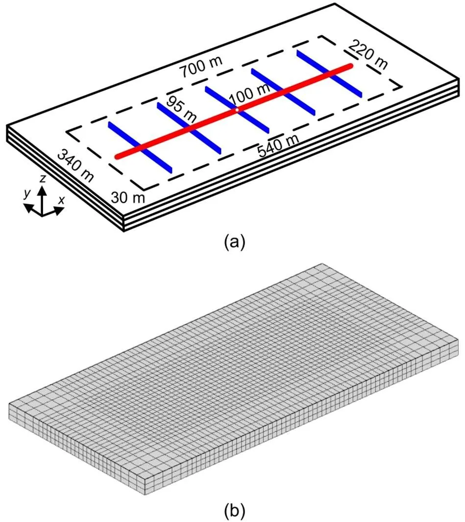
Fig. 10 Sketch of the shale gas reservoir (a) and the result of gridding (b). References to color refer to the online version of this figure
Table 2 Reservoir properties used for application and discussion
Three cases are presented here to study the effect of deformation hysteresis of hydraulic fractures on CO2huff-n-puff performance. In Case 1, a shale gas reservoir continuously produces for 10 a without CO2injection. In Cases 2 and 3, after 5 a of depletion production, CO2is injected for 18 months at a constant injection pressure (20 MPa), followed by 6 months of soaking, then the shale gas reservoir produces for 3 a. The only difference between Cases 2 and 3 is that hydraulic fracture deformation hysteresis is neglected in Case 2. Figs. 11a and 11b illustrate a comparison of gas pressure and CO2mole fractions between the different cases after 7 a. The gas pressure and CO2mole fractions in Cases 2 and 3 are obviously higher than those in Case 1. This means that the CO2huff-n-puff can re-pressurize the reservoir and sequestrate CO2. The gas pressure and CO2mole fraction in Case 3 are slightly different from those in Case 2. This is caused by the effect of deformation hysteresis. To better visualize the impact of the deformation hysteresis, Fig. 11c plots the gas pressure and CO2mole fraction along the observation line (∈[0, 700] m,=80 m, and=15 m) for Cases 2 and 3. The gas pressure and CO2mole fraction in Case 3 are both lower than those in Case 2. This is because deformation hysteresis hinders CO2injection.
Fig. 12 shows a comparison of CH4cumulative production, CO2cumulative sequestration, and CH4production rate among the three cases. The CO2huff-n-puff not only enhances CH4recovery, but also sequestrates CO2, but its performance declines when the deformation hysteresis of hydraulic fracture is considered. This could be partly because deformation hysteresis may hinder the recovery of hydraulic fracture permeability during the CO2huff-n-puff process. The evolution of normal effective stress and hydraulic fracture permeability at the observation point is shown in Fig. 13. Although the difference between the normal effective stress of Cases 2 and 3 is not obvious, the hydraulic fracture permeability of Case 3 is significantly lower than that of Case 2 due to the effect of hydraulic fracture deformation hysteresis.
During the production process, shale gas could be contaminated by the injected CO2. Therefore, CO2capture should be carried out to remove CO2from shale gas. According to the data from International Energy Agency (IEA), the average cost of CO2capture from natural gas is 20 USD/t (IEA, 2021), and the natural gas prices in Europe, Asia, and the USA are about 7.0, 25.0, and 25.0 USD/MMBtu, respectively (IEA, 2022). Here, MMBtu is the million British thermal units, and 1MMBtu=1.055 GJ. In Case 3, the amount of CO2that needs to be removed is 1.15×10⁷m3(22965.5 t), and the increase in natural gas (CH4) resulting from the use of CO2huff-n-puff is 9.8×10⁵m3(equivalent to 34608 MMBtu). The calculated average cost of CO2capture is 459310 USD, and the profit from increased natural gas is 242256 USD (in the USA) and 865200 USD (in Europe and Asia), respectively. Therefore, CO2huff-n-puff is cost-effective in Europe and Asia at present. In the future, it will become more cost-effective with further development of CO2capture.
Fig. 11 Comparison of gas pressure and CO2 mole fraction between different cases after 7 a: (a) gas pressure fields (MPa) of Case 1 (left), Case 2 (middle), and Case 3 (right); (b) CO2 mole fraction fields of Case 1 (left), Case 2 (middle), and Case 3 (right); (c) gas pressure (left) and CO2 mole fraction (right) along the observation line for Cases 2 and 3
In the above case study, the negative effect of hydraulic fracture deformation hysteresis on CO2huff-n-puff performance was roughly estimated, but this effect could be different under various reservoir properties and production conditions. Therefore, sensitivity analyses were carried out to understand when the effect of deformation hysteresis would be significant. In the following subsections, Cases 2 and 3 are used for the sensitivity analyses.
4.2.1Sensitivity to the initial conductivity of hydraulic fracture
First, we studied the sensitivity to the initial conductivity of hydraulic fracture through three cases with initial conductivity of 6, 12, and 24 mD·m (1 mD (millidarcy) is equivalent to 0.9869233×10⁻¹⁵m2, and here was approximated as 1×10–15m2). Fig. 14 shows a comparison of the CH4cumulative production, CO2cumulative sequestration, and CH4production rate among the different cases. When the deformation hysteresis was neglected, the errors of CH4cumulative production for the three cases were 4.03%, 1.85%, and 0.37%, respectively. The CO2huff-n-puff performance correlated positively with the initial conductivity of hydraulic fracture. In addition, the negative impact caused by deformation hysteresis on the enhanced CH4recovery decreased with the increase of initial conductivity. Therefore, the final design should strive to achieve highly conductive hydraulic fractures to enhance CO2huff-n-puff performance and reduce the negative effect caused by deformation hysteresis.
4.2.2Sensitivity to the starting time of huff-n-puff
Three cases with different starting times (i.e., after 3, 5, and 7 a, respectively) were constructed to study the sensitivity to the starting time. A comparison of the CH4cumulative production, CO2cumulative sequestration, and CH4production rate among the different cases is plotted in Fig. 15. When the deformation hysteresis is neglected, the errors of CH4cumulative production for the three cases were 1.17%, 1.85%, and 2.57%, respectively. A later starting time leads to a stronger negative effect of deformation hysteresis and a lower CH4recovery. Therefore, to reduce the negative effect of deformation hysteresis and improve CH4recovery, an early starting time of CO2huff-n-puff is recommended.
Fig. 12 Comparison of CH4 cumulative production and CO2 cumulative sequestration (a), and the CH4 production rate (b) among cases 1‒3
Fig. 14 Comparison of CH4 cumulative production and CO2 cumulative sequestration (a), and CH4 production rate (b) with different permeability. DH indicates deformation hysteresis
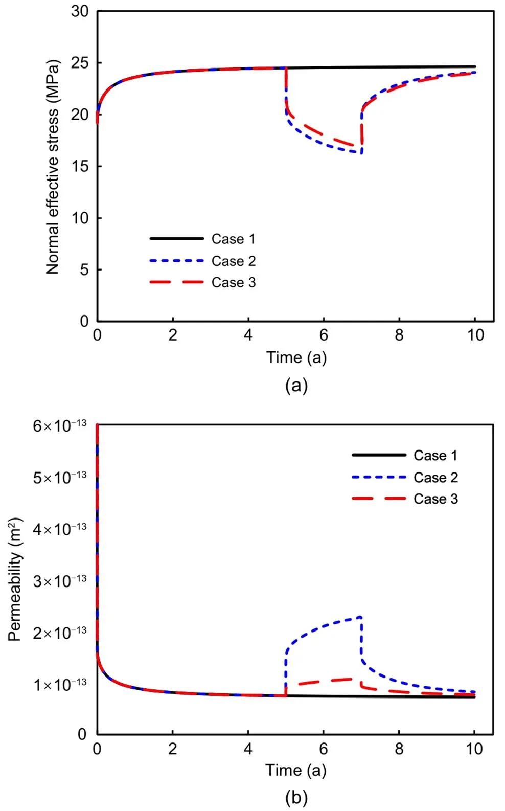
Fig. 13 Evolution of the normal effective stress acting on hydraulic fracture (a) and the hydraulic fracture permeability (b) at the observation point among cases 1‒3
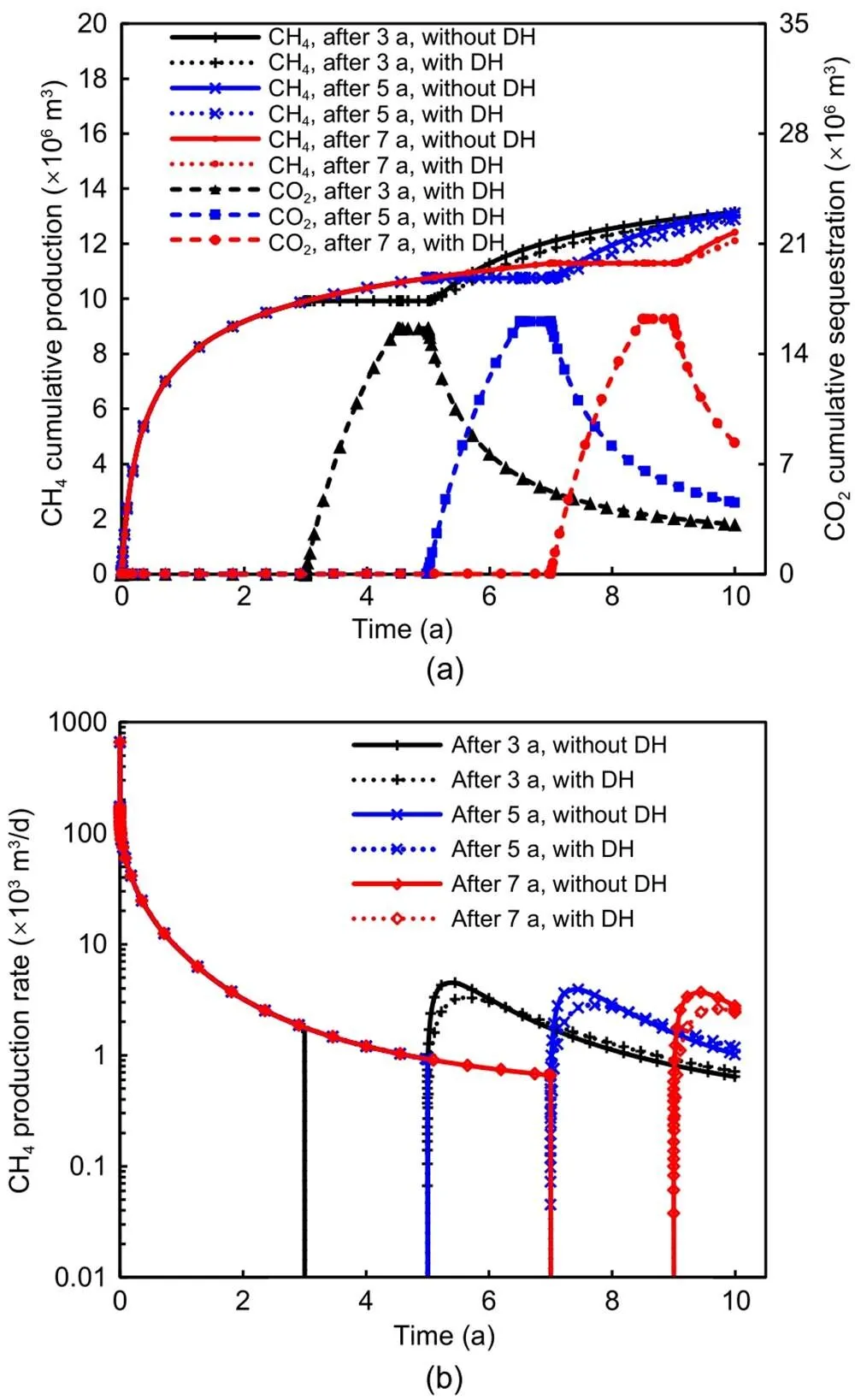
Fig. 15 Comparison of CH4 cumulative production and CO2 cumulative sequestration (a), and CH4 production rate (b) with different time
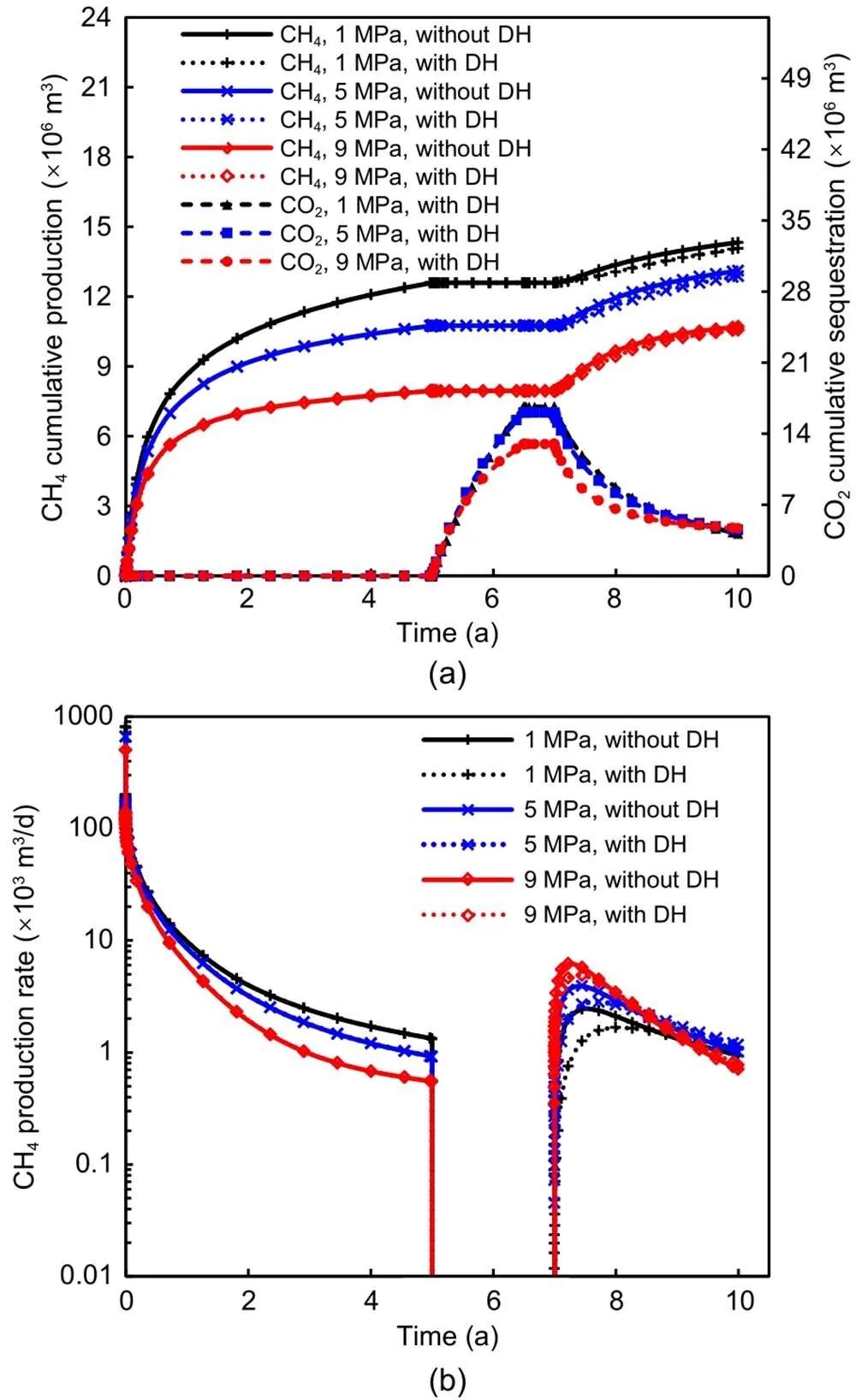
Fig. 16 Comparison of CH4 cumulative production and CO2 cumulative sequestration (a), and CH4 production rate (b) with different production pressures
4.2.3Sensitivity to production pressure
Here, we constructed three different cases with production pressures of 1, 5, and 9 MPa, respectively. Fig. 16 compares the performance of CO2huff-n-puff between the different cases. When deformation hysteresis was neglected, the errors of CH4cumulative production for the three cases were 2.13%, 1.85%, and 0.65%, respectively. This clearly shows that CH4cumulative production correlates negatively with the production pressure. Also, the negative effect of deformation hysteresis becomes more obvious as a lower production pressure is used. This is because a lower production pressure results in larger normal effective stress acting on the hydraulic fracture, leading to more significant differences in hydraulic fracture permeability among the cases with and without deformation hysteresis.
4.2.4Sensitivity to injection pressure
The sensitivity to injection pressure was studied using three different cases with injection pressures of 10, 15, and 30 MPa, respectively. Fig. 17 shows a comparison of CO2huff-n-puff performance among the different cases. When deformation hysteresis was neglected, the errors of CH4cumulative production for the three cases were 0.54%, 1.37%, and 2.04%, respectively. This shows that CO2huff-n-puff performance increases as the injection pressure incr eases. This is because the shale gas reservoir can be considerably re-pressurized as the injection pressure increases. In addition, the increase of injection pressure would result in more CO2being injected into the shale gas reservoir, thereby replacing more CH4due to competitive adsorption. Deformation hysteresis can lead to an obvious negative effect with high injection pressure. This is because a higher injection pressure results in a greater unloading force, and this further amplifies the differences in the permeability of the hydraulic fractures.
4.2.5Sensitivity to cycle number
Lastly, we studied three cases with different CO2huff-n-puff schemes to test sensitivity to cycle number. During the cycle of CO2huff-n-puff, CO2is injected for 5 months at a constant injection pressure (20 MPa), followed by 1 month of soaking, then 18 months of production by the shale gas reservoir. After 4 a of depletion production, the cycle of CO2huff-n-puff repeats for 1, 2, and 3 times in Cases 4, 5, and 6, respectively. After the CO2huff-n-puff process, the shale gas reservoir continues to produce for 10 a. Two different situations (i.e., without and with hydraulic fracture deformation hysteresis) were considered in each case.
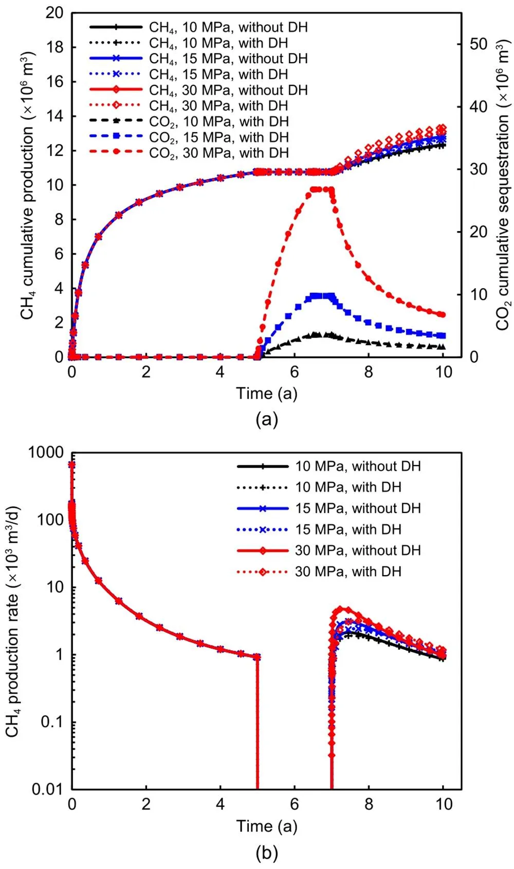
Fig. 17 Comparison of CH4 cumulative production and CO2 cumulative sequestration (a), and CH4 production rate (b) with different injection pressures
A comparison of CO2huff-n-puff performance among the different cases is given in Fig. 18. When the deformation hysteresis was neglected, the errors of CH4cumulative production for the three cases were 1.16%, 2.12%, and 3.49%, respectively. Note that the blue dashed line in Fig. 18 overlaps the black solid line at the end. This shows the CO2huff-n-puff performance correlated positively with the cycle number, and the negative effect of deformation hysteresis on the enhanced CH4recovery increased with the cycle number. This is because a higher cycle number leads not only to more CO2injection, but also to a longer period of exposure to the negative effects of deformation hysteresis. Therefore, to improve CO2huff-n-puff performance, multiple cycles are recommended, but the effect of deformation hysteresis cannot be ignored in this situation.
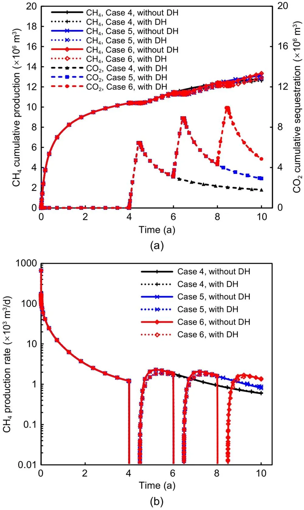
Fig. 18 Comparison of CH4 cumulative production and CO2 cumulative sequestration (a), and CH4 production rate (b) among cases 4‒6. References to color refer to the online version of this figure
5 Conclusions
In this paper, we have presented a fully coupled multi-component flow and geomechanics model, which includes viscous flow, molecular diffusion, Knudsen diffusion, multi-component adsorption, and path-dependent constitutive law, to evaluate CO2huff-n-puff performance in shale gas reservoirs considering hydr aulic fracture deformation hysteresis. A numerical solution method for the hydro-mechanical coupling model is also presented in detail. The proposed method was verified using some numerical examples, and then applied to some sensitivity analyses of the effect of hydraulic fracture deformation hysteresis on CO2huff-n-puff in a 3D shale gas reservoir. From the simulation results, we reached the following conclusions: (1) hydraulic fracture deformation hysteresis could hinder the recovery of fracture permeability during the CO2injection periods, and is unfavorable for CO2huff-n-puff performance; (2) a lower initial conductivity and production pressure, later starting time, higher injection pressure, and higher cycle number would increase the negative effects of deformation hysteresis; (3) CO2huff-n-puff performance correlates positively with the initial conductivity, starting time, injection pressure, and cycle number, but correlates negatively with the production pressure. In our future studies, the proposed method will be extended to consider thermal effects and coupling fracture propagation.
Acknowledgments
This work is supported by the National Natural Science Foundation of China (Nos. 52004321, 52034010, and 12131014), the Natural Science Foundation of Shandong Province, China (No. ZR2020QE116), and the Fundamental Research Funds for the Central Universities, China (Nos. 20CX06025A and 21CX06031A).
Author contributions
Xia YAN and Jun YAO designed the research. Xia YAN and Pi-yang LIU processed the corresponding data. Xia YAN wrote the first draft of the manuscript. Zhao-qin HUANG helped to organize the manuscript. Hai SUN, Kai ZHANG, and Jun-feng WANG revised and edited the final version.
Conflict of interest
Xia YAN, Pi-yang LIU, Zhao-qin HUANG, Hai SUN, Kai ZHANG, Jun-feng WANG, and Jun YAO declare that they have no conflict of interest.
Electronic supplementary materials
Section S1
CMG (Computer Modelling Group), 2015. GEM User’s Guide. Computer Modelling Group, Calgary, Canada.
COMSOL, 1998. Introduction to COMSOL Multiphysics®. COMSOL, Burlington, USA.
Du FS, Nojabaei B, 2019. A review of gas injection in shale reservoirs: enhanced oil/gas recovery approaches and greenhouse gas control. Energies, 12(12):2355. https://doi.org/10.3390/en12122355
Fan WP, Sun H, Yao J, et al., 2019. An upscaled transport model for shale gas considering multiple mechanisms and heterogeneity based on homogenization theory. Journal of Petroleum Science and Engineering, 183:106392. https://doi.org/10.1016/j.petrol.2019.106392
Fathi E, Akkutlu IY, 2014. Multi-component gas transport and adsorption effects during CO2 injection and enhanced shale gas recovery. International Journal of Coal Geology, 123:52-61. https://doi.org/10.1016/j.coal.2013.07.021
Gala D, Sharma M, 2018. Compositional and geomechanical effects in huff-n-puff gas injection IOR in tight oil reservoirs. SPE Annual Technical Conference and Exhibition, p.1-24. https://doi.org/10.2118/191488-MS
Garipov TT, Karimi-Fard M, Tchelepi HA, 2016. Discrete fracture model for coupled flow and geomechanics. Computational Geosciences, 20(1):149-160. https://doi.org/10.1007/s10596-015-9554-z
Ghanizadeh A, Clarkson CR, Deglint H, et al., 2016. Unpropped/propped fracture permeability and proppant embedment evaluation: a rigorous core-analysis/imaging methodology. Proceedings of the SPE/AAPG/SEG Unconventional Resources Technology Conference, p.1824-1852. https://doi.org/10.15530/URTEC-2016-2459818
Giger F, Reiss L, Jourdan A, 1984. The reservoir engineering aspects of horizontal drilling. SPE Annual Technical Conference and Exhibition, p.1-8. https://doi.org/10.2118/13024-MS
Godec M, Koperna G, Petrusak R, et al., 2014. Enhanced gas recovery and CO2 storage in gas shales: a summary review of its status and potential. Energy Procedia, 63:5849-5857. https://doi.org/10.1016/j.egypro.2014.11.618
Hasan M, Eliebid M, Mahmoud M, et al., 2017. Enhanced gas recovery (EGR) methods and production enhancement techniques for shale & tight gas reservoirs. SPE Kingdom of Saudi Arabia Annual Technical Symposium and Exhibition, p.1-9. https://doi.org/10.2118/188090-MS
Huang JW, Jin TY, Barrufet M, et al., 2020. Evaluation of CO2 injection into shale gas reservoirs considering dispersed distribution of kerogen. Applied Energy, 260:114285. https://doi.org/10.1016/j.apenergy.2019.114285
Hubbert M, Willis DG, 1957. Mechanics of hydraulic fracturing. Transactions of the AIME, 210(1):153-168. https://doi.org/10.2118/686-G
IEA (International Energy Agency), 2021. Levelised Cost of CO2 Capture by Sector and Initial CO2 Concentration, 2019. IEA, Paris, France. https://www.iea.org/data-and-statistics/charts/levelised-cost-of-co2-capture-by-sector-and-initial-co2-concentration-2019
IEA (International Energy Agency), 2022. Natural Gas Prices in Europe, Asia and the United States, Jan 2020-February 2022. IEA, Paris, France. https://www.iea.org/data-and-statistics/charts/natural-gas-prices-in-europe-asia-and-the-united-states-jan-2020-february-2022
Jaeger JC, Cook NGW, Zimmerman RW, 2007. Fundamentals of Rock Mechanics, 4th Edition. Blackwell Publishing, Oxford, UK, p.189-194.
Jiang JM, Yang J, 2018. Coupled fluid flow and geomechanics modeling of stress-sensitive production behavior in fractured shale gas reservoirs. International Journal of Rock Mechanics and Mining Sciences, 101:1-12. https://doi.org/10.1016/j.ijrmms.2017.11.003
Jiang JM, Shao YY, Younis RM, 2014. Development of a multi-continuum multi-component model for enhanced gas recovery and CO2 storage in fractured shale gas reservoirs. SPE Improved Oil Recovery Symposium, p.1-17. https://doi.org/10.2118/169114-MS
Karlsson H, Jacques GE, Hatten JL, et al., 1991. Method and Apparatus for Horizontal Drilling. US Patent 5074366.
Khoei AR, 2014. Extended Finite Element Method: Theory and Applications. John Wiley & Sons, Chichester, UK.
Kim J, Moridis GJ, 2014. Gas flow tightly coupled to elastoplastic geomechanics for tight-and shale-gas reservoirs: material failure and enhanced permeability. SPE Journal, 19(6):1110-1125. https://doi.org/10.2118/155640-PA
Kim J, Sonnenthal EL, Rutqvist J, 2012. Formulation and sequential numerical algorithms of coupled fluid/heat flow and geomechanics for multiple porosity materials. International Journal for Numerical Methods in Engineering, 92(5):425-456. https://doi.org/10.1002/nme.4340
Kim TH, Cho J, Lee KS, 2017. Evaluation of CO2 injection in shale gas reservoirs with multi-component transport and geomechanical effects. Applied Energy, 190:1195-1206. https://doi.org/10.1016/j.apenergy.2017.01.047
Li HL, Lu YY, Zhou L, et al., 2017. A new constitutive model for calculating the loading-path dependent proppant deformation and damage analysis of fracture conductivity. Journal of Natural Gas Science and Engineering, 46:365-374. https://doi.org/10.1016/j.jngse.2017.08.005
Li ZY, Elsworth D, 2019. Controls of CO2–N2 gas flood ratios on enhanced shale gas recovery and ultimate CO2 sequestration. Journal of Petroleum Science and Engineering, 179:1037-1045. https://doi.org/10.1016/j.petrol.2019.04.098
Liu FS, Borja RI, 2010. Stabilized low-order finite elements for frictional contact with the extended finite element method. Computer Methods in Applied Mechanics and Engineering, 199(37-40):2456-2471. https://doi.org/10.1016/j.cma.2010.03.030
Liu J, Wang JG, Gao F, et al., 2019. A fully coupled fracture equivalent continuum-dual porosity model for hydro-mechanical process in fractured shale gas reservoirs. Computers and Geotechnics, 106:143-160. https://doi.org/10.1016/j.compgeo.2018.10.017
Liu JS, Chen ZW, Elsworth D, et al., 2011. Interactions of multiple processes during CBM extraction: a critical review. International Journal of Coal Geology, 87(3-4):175-189. https://doi.org/10.1016/j.coal.2011.06.004
Liu LJ, Yao J, Sun H, et al., 2019. Compositional modeling of shale condensate gas flow with multiple transport mechanisms. Journal of Petroleum Science and Engineering, 172:1186-1201. https://doi.org/10.1016/j.petrol.2018.09.030
Liu LJ, Liu YZ, Yao J, et al., 2020a. Efficient coupled multiphase-flow and geomechanics modeling of well performance and stress evolution in shale-gas reservoirs considering dynamic fracture properties. SPE Journal, 25(3):1523-1542. https://doi.org/10.2118/200496-PA
Liu LJ, Liu YZ, Yao J, et al., 2020b. Mechanistic study of cyclic water injection to enhance oil recovery in tight reservoirs with fracture deformation hysteresis. Fuel, 271:117677. https://doi.org/10.1016/j.fuel.2020.117677
Lohrenz J, Bray BG, Clark CR, 1964. Calculating viscosities of reservoir fluids from their compositions. Journal of Petroleum Technology, 16(10):1171-1176. https://doi.org/10.2118/915-PA
Mahmoodpour S, Singh M, Turan A, et al., 2022a. Simulations and global sensitivity analysis of the thermo-hydraulic-mechanical processes in a fractured geothermal reservoir. Energy, 247:123511. https://doi.org/10.1016/j.energy.2022.123511
Mahmoodpour S, Singh M, Bär K, et al., 2022b. Thermo-hydro-mechanical modeling of an enhanced geothermal system in a fractured reservoir using carbon dioxide as heat transmission fluid-a sensitivity investigation. Energy, 254:124266. https://doi.org/10.1016/j.energy.2022.124266
Moinfar A, Varavei A, Sepehrnoori K, et al., 2012. Development of a novel and computationally-efficient discrete-fracture model to study IOR processes in naturally fractured reservoirs. SPE Improved Oil Recovery Symposium, p.1-17. https://doi.org/10.2118/154246-MS
Norbeck JH, McClure MW, Lo JW, et al., 2016. An embedded fracture modeling framework for simulation of hydraulic fracturing and shear stimulation. Computational Geosciences, 20(1):1-18. https://doi.org/10.1007/s10596-015-9543-2
Pruess K, 1991. TOUGH2: a General-Purpose Numerical Simulator for Multiphase Fluid and Heat Flow. LBL-29400, Lawrence Berkeley Lab, Berkeley, USA.
Qiu YL, Wu CJ, Chen WF, 2020. Local heat transfer enhancement induced by a piezoelectric fan in a channel with axial flow. Journal of Zhejiang University-SCIENCE A (Applied Physics & Engineering), 21(12):1008-1022. https://doi.org/10.1631/jzus.A2000057
Ren G, Jiang J, Younis RM, 2016. Fully coupled geomechanics and reservoir simulation for naturally and hydraulically fractured reservoirs. The 50th U.S. Rock Mechanics/Geomechanics Symposium, p.1-12.
Ryder RT, 1996. Fracture Patterns and Their Origin in the Upper Devonian Antrim Shale Gas Reservoir of the Michigan Basin: a Review. Open-File Report 96-23, U.S. Geological Survey, Reston, USA.
Shah M, Shah S, Sircar A, 2017. A comprehensive overview on recent developments in refracturing technique for shale gas reservoirs. Journal of Natural Gas Science and Engineering, 46:350-364. https://doi.org/10.1016/j.jngse.2017.07.019
Song WH, Yao J, Li Y, et al., 2016. Apparent gas permeability in an organic-rich shale reservoir. Fuel, 181:973-984. https://doi.org/10.1016/j.fuel.2016.05.011
Striolo A, Cole DR, 2017. Understanding shale gas: recent progress and remaining challenges. Energy & Fuels, 31(10):10300-10310. https://doi.org/10.1021/acs.energyfuels.7b01023
Sun H, Yao J, Cao YC, et al., 2017. Characterization of gas transport behaviors in shale gas and tight gas reservoirs by digital rock analysis. International Journal of Heat and Mass Transfer, 104:227-239. https://doi.org/10.1016/j.ijheatmasstransfer.2016.07.083
Urban E, Orozco D, Fragoso A, et al., 2016. Refracturing vs. infill drilling–a cost effective approach to enhancing recovery in shale reservoirs. SPE/AAPG/SEG Unconventional Resources Technology Conference, p.2934-2953. https://doi.org/10.15530/URTEC-2016-2461604
Vermylen JP, 2011. Geomechanical Studies of the Barnett Shale, Texas, USA. PhD Thesis, Stanford University, California, USA.
Versteeg HK, Malalasekera W, 1995. An Introduction to Computational Fluid Dynamics: the Finite Volume Method. Longman Scientific & Technical, New York, USA.
Wang DY, Yao J, Chen ZX, et al., 2019. Image-based core-scale real gas apparent permeability from pore-scale experimental data in shale reservoirs. Fuel, 254:115596. https://doi.org/10.1016/j.fuel.2019.06.004
Webb SW, Pruess K, 2003. The use of Fick’s law for modeling trace gas diffusion in porous media. Transport in Porous Media, 51(3):327-341. https://doi.org/10.1023/A:1022379016613
Wu YS, Li JF, Ding DY, et al., 2014. A generalized framework model for the simulation of gas production in unconventional gas reservoirs. SPE Journal, 19(5):845-857. https://doi.org/10.2118/163609-PA
Xu RN, Zeng KC, Zhang CW, et al., 2017. Assessing the feasibility and CO2 storage capacity of CO2 enhanced shale gas recovery using triple-porosity reservoir model. Applied Thermal Engineering, 115:1306-1314. https://doi.org/10.1016/j.applthermaleng.2017.01.062
Yan X, Huang ZQ, Yao J, et al., 2016. An efficient embedded discrete fracture model based on mimetic finite difference method. Journal of Petroleum Science and Engineering, 145:11-21. https://doi.org/10.1016/j.petrol.2016.03.013
Yan X, Huang ZQ, Yao J, et al., 2018a. An efficient hydro-mechanical model for coupled multi-porosity and discrete fracture porous media. Computational Mechanics, 62(5):943-962. https://doi.org/10.1007/s00466-018-1541-5
Yan X, Huang ZQ, Yao J, et al., 2018b. An efficient numerical hybrid model for multiphase flow in deformable fractured-shale reservoirs. SPE Journal, 23(4):1412-1437. https://doi.org/10.2118/191122-PA
Yan X, Huang ZQ, Zhang Q, et al., 2020. Numerical investigation of the effect of partially propped fracture closure on gas production in fractured shale reservoirs. Energies, 13(20):5339. https://doi.org/10.3390/en13205339
Ye X, Tonmukayakul P, Weaver JD, et al., 2012. Experiment and simulation study of proppant pack compression. SPE International Symposium and Exhibition on Formation Damage Control, p.1-12. https://doi.org/10.2118/151647-MS
Yu W, Sepehrnoori K, 2014. Simulation of gas desorption and geomechanics effects for unconventional gas reservoirs. Fuel, 116:455-464. https://doi.org/10.1016/j.fuel.2013.08.032
Zeng QD, Yao J, Shao JF, 2018. Numerical study of hydraulic fracture propagation accounting for rock anisotropy. Journal of Petroleum Science and Engineering, 160:422-432. https://doi.org/10.1016/j.petrol.2017.10.037
Zeng QD, Yao J, Shao JF, 2019. Study of hydraulic fracturing in an anisotropic poroelastic medium via a hybrid EDFM-XFEM approach. Computers and Geotechnics, 105:51-68. https://doi.org/10.1016/j.compgeo.2018.09.010
Zhang Q, Borja RI, 2021. Poroelastic coefficients for anisotropic single and double porosity media. Acta Geotechnica, 16(10):3013-3025. https://doi.org/10.1007/s11440-021-01184-y
Zhang Q, Yan X, Shao JL, 2021. Fluid flow through anisotropic and deformable double porosity media with ultra-low matrix permeability: a continuum framework. Journal of Petroleum Science and Engineering, 200:108349. https://doi.org/10.1016/j.petrol.2021.108349
Zhang Q, Yan X, Li ZH, 2022. A mathematical framework for multiphase poromechanics in multiple porosity media. Computers and Geotechnics, 146:104728. https://doi.org/10.1016/j.compgeo.2022.104728
Zhu GP, Kou JS, Yao BW, et al., 2019. Thermodynamically consistent modelling of two-phase flows with moving contact line and soluble surfactants. Journal of Fluid Mechanics, 879:327-359. https://doi.org/10.1017/jfm.2019.664
Zienkiewicz OC, Taylor RL, 2000. The Finite Element Method: Solid Mechanics. Butterworth-Heinemann, Oxford, UK.
Zuloaga P, Yu W, Miao JJ, et al., 2017. Performance evaluation of CO2 huff-n-puff and continuous CO2 injection in tight oil reservoirs. Energy, 134:181-192. https://doi.org/10.1016/j.energy.2017.06.028
Mar. 19, 2022; Revision accepted July 11, 2022; Crosschecked Sept. 13, 2022; Online first Dec. 17, 2022
https://doi.org/10.1631/jzus.A2200142
© Zhejiang University Press 2022
 Journal of Zhejiang University-Science A(Applied Physics & Engineering)2023年1期
- Journal of Zhejiang University-Science A(Applied Physics & Engineering)的其它文章
- Multiscale multiphysics modeling in geotechnical engineering
- CFD-DEM modelling of suffusion in multi-layer soils with different fines contents and impermeable zones
- Finite volume method-based numerical simulation method for hydraulic fracture initiation in rock around a perforation
- Numerical investigations of the failure mechanism evolution of rock-like disc specimens containing unfilled or filled flaws
- Mechanistic investigation on Hg0 capture over MnOx adsorbents: effects of the synthesis methods
- Modelling and applications of dissolution of rocks in geoengineering