A Novel Multi-Granularity Flexible-Grid Switching Optical-Node Architecture
Zhenfang Huang ,Bo Zhu,* ,Mingchen Zhu ,Mengyue Jiang ,Xinting Song ,Jiawei Zhao ,Zheng Wang,Fangren Hu
1 College of Electronic and Optical Engineering&College of Microelectronics,Nanjing University of Posts and Telecommunications,Nanjing 210023,China
2 SUFA Technology Industry Co.,Ltd.,CNNC,Suzhou 215001,China
Abstract: A novel multi-granularity flexible-grid switching optical-node architecture is proposed in this paper.In our system,the photonic lanterns are used as mode division multiplexing/demultiplexing (MD-Mux/MD-Demux) for selecting mode.The wavelength division multiplexer/demultiplexer (WDMux/WD-Demux)and the fiber bragg gratings(FBGs)are used to select wavelength channels with the various grid.The experimental results show that the transmission bandwidth covers the C+L band,the average transmission loss is-13.4 dB,and the average crosstalk is -30.5 dB.The optical-node architecture is suit for mode division multiplexing (MDM) optical communication system.
Keywords: optical node;multi-granularity switching;flexible-grid switching
I.INTRODUCTION
Due to the rapid growth of business demand,the development of optical networks is facing the dual pressures of improving transmission capacity and bandwidth flexibility[1].The traditional dense wavelength division multiplexing (DWDM) technology will no longer be suitable for the traffic with large capacity,high dynamic,and strong burst characteristics in the 5G era [2,3].Space division multiplexing (SDM)technology is attracting attention as an upcoming technology for future ultra-large capacity optical networks[4-9].
The current solutions of node structure can be roughly classified into two categories:integrated solution and discrete component solution.The integrated solution means that all functions are integrated on a chip.For example,the structures proposed in references [10,11] have the functions of mode switching and wavelength switching.However,the mode it can switch is the planar waveguide transverse magnetic (TM) mode.Therefore,the mode conversion between TM and linear polarization (LP) will be involved when the structure is applied to a few-mode fiber (FMF) communication system.The structure in reference [12] is based on the Mach-Zehnder Interferometer (MZI) principle,which can realize mode switching and wavelength switching.However,the scale of switching is 2×2,and its performance is related to the polarization of the input signal.The structure in reference[13]is based on the principle of semiconductor optical amplifier,which can realize wavelength switching.However,it cannot realize mode switching.The scale of switching is 2 × 2,and its performance is also related to the polarization of the input signal.The structure proposed in reference[14]is designed by applying the principle of inter-modal four-wave mixing,which can realize the functions of mode switching and wavelength switching.However,the scale of switching is 3 × 3,and the efficiency of parametric process is not high.In summary,the advantage of the integrated solution is easy to integrate,and the disadvantage is a little far from practical applications.
Another category consists of discrete components.For example,the structures proposed in references[15-19] mainly consist of MD-Mux/MD-Demux and wavelength selector switches (WSSs).They can realize the functions of mode switching,wavelength switching and traffic adding/dropping.However,their structures need to use a large number of WSSs,and the systems are more complex.In addition,their structures do not have the function of flexible-gird switching.The structure is based on one pair of N×N cyclic array waveguide gratings (AWGs) and tunable FBGs proposed in reference [20].It can realize the functions of wavelength switching,flexible-grid switching and traffic adding/dropping.However,their structure does not support mode switching.The structure proposed in reference [21] has the functions of flexiblegrid switching and mode switching.In which,spectrum selective switches (SSSs) have replaced fixedgrid WSSs to support elastic spectrum allocation for finer granularity.However,their structure needs to use a large number of SSSs.
This paper adopts discrete component solution,which mainly consists of MD-Mux/MD-Demux,FBGs and optical matrix switches.Our architecture can be directly used in the actual communication system,and its performance is not related to the polarization of the input signal.Our architecture could realize the functions of multi-granularity switching,traffic adding/dropping and optical performance monitoring.The multi-granularity refers to FMF-level,mode-level,wavelength-level and flexible-grid level.Compared with the structure proposed in reference,our structure has more functions.Under the same switching scale condition,the number of optical matrix switches used in our proposed structure are less than the number of WSSs or SSSs used in the structures proposed in references.
II.ARCHITECTURE DESCRIPTION AND WORKING PRINCIPLE
2.1 Design of the Multi-granularity Flexiblegrid Switching Optical-node
Figure 1 illustrates the configuration of the two-layer switching optical-node.The first layer is composed of optical switch 1 and MD-Mux/MD-Demux,which completes the FMF-level switching and mode-level switching.The port sizes of optical switch 1 is 32×32,with 32 input(I)ports and 32 output(O)ports,respectively named I1-I32 and O1-O32.24 I/O(I1-I12,O1-O12)ports are respectively connected with 3 ports of 4 MD-Mux/MD-Demux to form 4 FMF-level ports,16 mode-level I/O (I13-I20,O13-O20) ports,20 add/drop (I21-I30,O21-O30) ports (only two ports are shown in Figure 1 as examples)and 4 WDM I/O(I31-I32,O31-O32) ports.The second layer is consisted of optical switch 2,WD-Mux/WD-Demux,circulators,static FBGs and tunable FBGs to complete the switching of fixed-grid and flexible-grid signals.The tunable FBG is linearly chirped fiber bragg grating(LCFBG),which is different from the static FBG.The static FBG needs to be used with a circulator,but the tunable FBG can be used without a circulator.Due to the thermo-optical effect,a phase shift can be induced along the LCFBG by heating a small portion of the LCFBG,and then a transmission peak can be obtained within the stop band.The tunable FBG uses a thermal printer head as a digital heating unit to accurately heat the specific location of the fiber grating.The location(center wavelength)of the transmission peaks can be set by changing the location of the heating points,and the peak’s bandwidth(channel bandwidth)can be tuned by changing the width of the heating region.The ports size of optical switch 2 are the same as the optical switch 1,and the ports are named I1-I32 and O1-O32 respectively.4 (I1-I4,I8-I11,O1-O4,O8-O11) WD-Mux/WD-Demux configured,18 flexiblegrid level I/O (I5-I7,I12-I14,I18-I20,O5-O7,O12-O14,O18-O20) ports,6 wavelength-level I/O (I15-I17,O15-O17)ports,24 add/drop(I21-I32,O21-O32)ports (only two ports are shown in Figure 1 as examples).The architecture has the functions of multigranularity switching,flexible-grid switching,traffic adding/dropping,service aggregation,and optical performance monitoring.
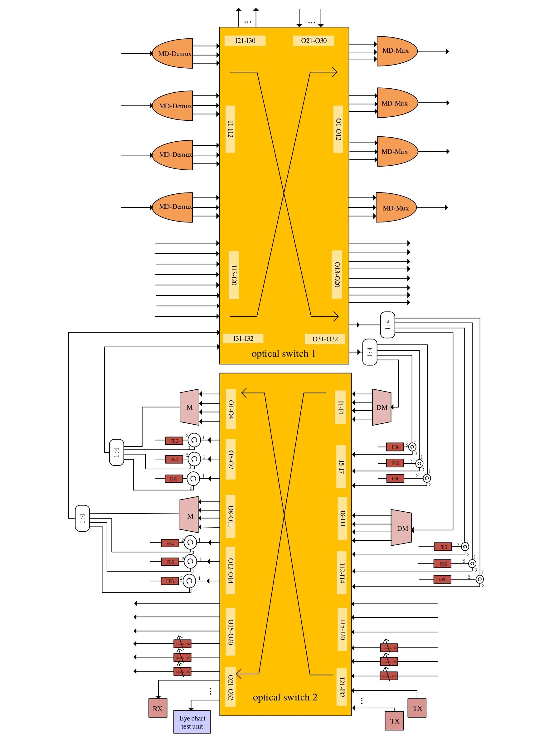
Figure 1. Schematic diagram of multi-granularity flexible-grid switching optical node architecture.
2.2 FMF-Level,Mode-Level,Flexible-Grid Level and Wavelength-Level Switching
The mode and wavelength switching functions can be realized by assigning the optical switch 1 or 2 in Figure 1.For the implementation of the FMF-level optical channel switching,we configure I7-O1,I8-O2,and I9-O3 of optical switch 1,the optical channel of FMFlevel entrance 3 can be switched to the FMF-level exit 1.By configuring I18-O20 of optical switch 2,the optical channel of flexible-grid level can be switched from I18 to O20.The optical switch has no restriction on the channel.Furthermore,the bandwidth of optical channel can be arbitrarily selected from 12.5 GHz or 25 GHz,meeting the requirements of flexible-grid level switching.
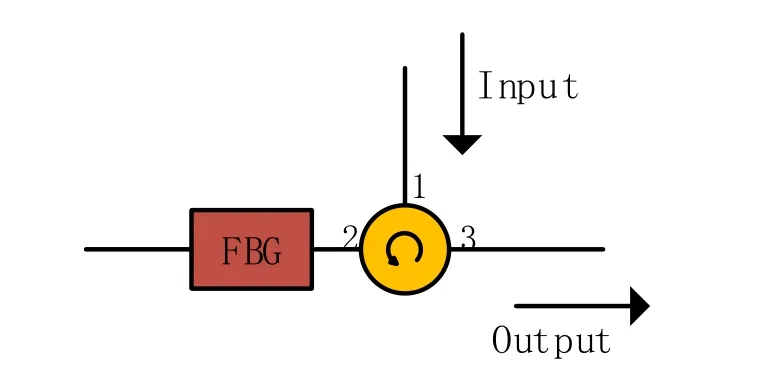
Figure 2. Schematic diagram of selection of flexible bandwidth.
2.3 Add/Drop Traffic
In our design,the add/drop traffic of various granularity are completed by optical switch.To download the mode-level service from FMF-level service,we only need to assign the optical switch 1.To add or drop the flexible-grid level service or wavelength-level service from FMF-level service,we need to assign optical switch 1 and optical switch 2 at the same time.For instance,the second flexible-grid service of the first FMF channel of FMF-level entrance 3 needs to be dropped,we connect I7-O32 of optical switch 1 and I6-O31 of optical switch 2.Then the second flexiblegrid service in the first FMF channel can be downloaded from O31 of optical switch 2.We only need to assign optical switch 2 to download wavelength-level service from wavelength-level service.As for adding traffic,we demonstrate by adding the flexible-grid service of I20 of the optical switch 2.We connect I31-O5 of optical switch 1,I20-O12 of optical switch 2 at the same time.
2.4 Service Aggregation
In order to illustrate the multi-granularity aggregation of our architecture,we assume that there are two mode services (I4,I5) in FMF-level entrance 2 and 6 services from optical switch 2 (I15-I20) (I15-I17 are 3 wavelength-level services,I18-I20 are 3 flexiblegrid level services),the transmission destination is the same.We connect the I4-O1,I5-O2,I31-O3 of optical switch 1,and I15-O8,I16-O9,I17-O10,I18-O12,I19-O13,I20-O14 of optical switch 2 at the same time.So,all services are aggregated on FMF exit 1 of optical switch 1,complete the all-optical service aggregation.
2.5 Optical Performance Monitoring
We use eye diagram test method to complete the monitoring function of our system.
III.EXPERIMENTAL SETUP AND DEMONSTRATION OF THE FUNCTIONS
3.1 Implement the Selection of Flexible Bandwidth
The schematic diagram of flexible bandwidth selection is shown in Figure 2.FBG with simple structure and good reflection characteristics which is used to select the flexible bandwidth.The parameters of FBG:pigtail length is 1 meter,the grid area is 10mm,and the reflectivity is greater than 90%.Furthermore,the bandwidths are all 25GHz and center wavelengths are 1560.4nm,1560.6nm,1560.9nm,which can meet the requirements for flexible-grid level switching.According to Figure 2,the optical signal is input from port 1 of the circulator and reflected by the FBG.We get the optical signal with a bandwidth of 0.2nm at port 3 of the circulator,and the central wavelength is optional (designed by us).With the development of technology,the novel FBG can dynamically select the center wavelength and bandwidth,but the price of the component is relatively expensive.If we use this kind of FBG,our architecture can also dynamically select the center wavelength and bandwidth to add/drop traffic.
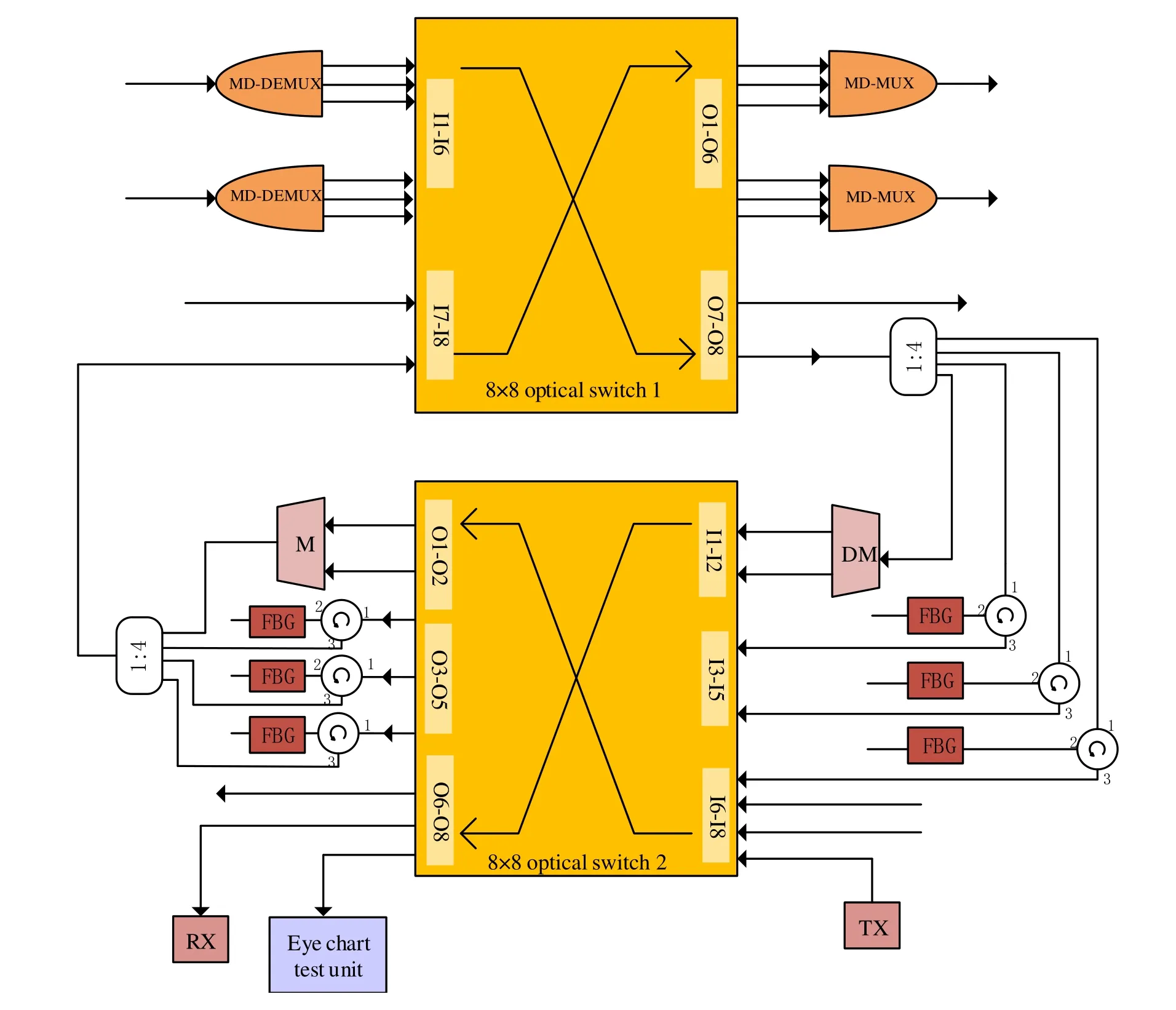
Figure 3. Schematic diagram of experimental system.
3.2 Implement of Optical Switching and MDMux/MD-Demux
In the experiment,we used 8×8 (I1-I8,O1-O8) commercial LightLEADER3424 optical matrix switch,which was controlled by LynxVISION software installed on the server.The transmission loss of optical switch is-3.5 dB,the crosstalk is-40 dB.
We used 6-mode selective photonic lantern as MDMux/MD-Demux,which was produced by CAILabs.It can multiplex the 6 modes (LP01,LP11a,LP11b,LP21a,LP21b,LP02)to any FMF or demultiplex the signal from the FMF.The average transmission loss of photonic lantern is-7 dB and the average crosstalk is-29.3 dB.
3.3 Experimental System
The schematic diagram of experimental system is shown in Figure 3.The port sizes of optical switch 1 and switch 2 are both 8×8,with 8 input (I) ports and 8 output (O) ports,respectively named I1-I8 and O1-O8.12 ports(I1-I6,O1-O6)for switching,2 ports(I7,O7)for adding/dropping,and 2 ports(I8,O8)for connecting with the optical switch 2.In optical switch 2,we allocated 4 WD-Mux/WD-Demux ports (I1-I2,O1-O2),6 flexible-grid level ports (I3-I5,O3-O5),2 wavelength-level ports(I6,O6),and 4 add/drop ports(I7-O7,I8-O8).
3.4 The Demonstration of the Flexible-grid Switching and Service Aggregation
Firstly,we demonstrate the flexible-grid level switching.By configuring the LynxVISION software on the server,we connect I6-O6,I7-O7,and I8-O8 of optical switch 2 in sequence.We chose three flexible-grid signals with different center wavelength to test the transmission performance,the tested results are shown in Figure 4.The center wavelength of the signals are 1560.4 nm,1560.6 nm,1560.9 nm respectively,and the bandwidth are all 25 GHz.Optical spectrum analyzer was used to test the spectrum of before and after flexible-grid switching,as shown in Figure 4(a),(b),and(c),respectively.It shows that our architecture has the function of flexible-grid switching.
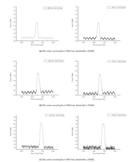
Figure 4. Spectrum diagrams of the signal before flexible-grid level switching (on the left) and after flexible-grid level switching(on the right).
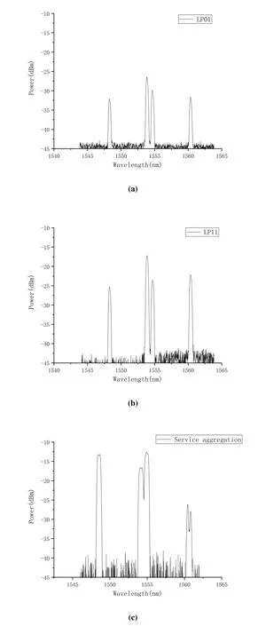
Figure 5. Schematic diagram of the spatial service aggregation.
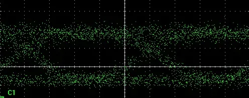
Figure 6. Eye diagram of the second channel(LP11 mode)of FMF-level entrance 1.
The following is a demonstration of service aggregation.We assume that the two input ports (I1,I2)of optical switch 1 and three input ports (I6,I7,I8)of optical switch 2 are aggregated to optical switch 1(O6).I1,I2 of optical switch 1 are two mode-level service ports.I6 of optical switch 2(1548.51 nm)is a wavelength-level service port.I7,I8 of optical switch 2 (1560.4 nm,1560.9 nm) are two flexible-grid level service ports.By controlling the LynxVISION software on the server,we connect I6-O2,I7-O3,I8-O4 of optical switch 2,I8-O6 of optical switch 1.That is,the service is output from FMF-level exit 2.Meanwhile,we connect I1-O4 and I2-O5 of optical switch 1.In order to test the service aggregation capability of the node,we use a mode selective photonic lanterns to demultiplex the signal from the FMF into three non-degenerate modes (LP01,LP11 and LP21),and test the spectrum of the demultiplexed signals respectively,as shown in Figure 5.It can be seen from Figure 5(a),(b),and(c)that the architecture has the service aggregation capability of FMF-level,mode-level,wavelength-level,and flexible-grid level.
In addition,we can use the eye diagram to monitor the performance of any signal through the optical node.For example,we can monitor the performance of first wavelength service of the second channel(LP11 mode)of FMF-level entrance 1.We connect I2-O8 of optical switch 1,I1-O8 of optical switch 2 at the same time.As shown in Figure 6,the eye diagram is measured by the oscilloscope.
IV.CONCLUSION
Based on FBG and optical switches,a novel opticalnode architecture is presented in the paper,we give the system diagram and experimental results.The architecture realizes the functions of multi-granularity switching,service aggregation,add/drop traffic and optical performance monitoring.Especially,it supports both fixed-grid and flexible-grid signal switching,enabling the flexible selection of service signal.
- China Communications的其它文章
- Secrecy Transmission of NOMA-OTFS Based Multicast-Unicast Streaming
- Orthogonal Time Frequency Space Modulation in 6G Era
- Joint Multi-Domain Channel Estimation Based on Sparse Bayesian Learning for OTFS System
- BER Performance Analysis of OTFS Systems with Power Allocation
- OTFS-Based Efficient Handover Authentication Scheme with Privacy-Preserving for High Mobility Scenarios
- Channel Estimation for OTFS System over Doubly Spread Sparse Acoustic Channels

