Modeling and Channel Estimation for Piezo-Acoustic Backscatter Assisted Underwater Acoustic Communications
Junliang Lin,Gongpu Wang,*,Zijian Zheng,Ruyi Ye,Ruisi He,4,Bo Ai,4
1 School of Computer and Information Technology,Beijing Jiaotong University,Beijing 100091,China
2 School of Electronic and Information Engineering,Beijing Jiaotong University,Beijing 100091,China
3 China National Institute of Standardization,Beijing 100088,China
4 The State Key Laboratory of Rail Traffic Control and Safety,Beijing Jiaotong University,Beijing 100091,China
Abstract: Relying on direct and converse piezoelectric effects,piezo-acoustic backscatter(PAB)technology reflects ambient acoustic signals to enable underwater backscatter communications at near-zero power,which was first realized through a prototype.In this paper,we propose a mathematical model of the PAB assisted underwater acoustic (UWA) communication,and address the sparse channel estimation problem.First,we present a five-stage backscatter process to derive the backscatter coefficient,and propose the channel model for the shallow-water communications.Then,we formulate the shallow-water acoustic channel estimation problem as a sparse vector recovery one according to the compressed sensing theory,and leverage the orthogonal matching pursuit(OMP)algorithm to obtain the channel estimator.Finally,simulation results are provided to corroborate our proposed studies.
Keywords: channel estimation; compressed sensing;piezo-acoustic backscatter; underwater acoustic communications
I.INTRODUCTION
Past decades have witnessed a growing market of underwater exploitation of the Internet of Things(IoT).Underwater IoT has covered various fields,such as instrument monitoring,pollution control,climate recording,and marine life investigation [1].The distinct variety of applications promotes the underwater IoT industry and endows underwater communications with prominently strategic significance.
However,one major bottleneck restricting underwater IoT development is the power consumption.For most existing systems,one IoT device has to generate and amplify the carrier acoustic signals to communicate with others,which consumes a few hundred watts even for low-power acoustic transmitters [2].Drastic power consumption is unaffordable for low-cost IoT devices with limited batteries.Thus,most of the underwater IoT systems are incapable of operating on the premise of power shortage.
Seen as a promising solution,piezo-acoustic backscatter (PAB) technology is recently proposed to alleviate the power issue facing underwater IoT devices[3].The terminology piezo comes from ancient Greek,meaning pressure or stress.The advantage of introducing PAB lies in that the IoT device can communicate with others by simply modulating and reflecting the ambient acoustic signal,instead of sending carrier actively.Hence,passive transmissions through PAB save much energy,which differs from traditional active underwater acoustic(UWA)communications.
The key enabler of PAB is the usage of direct and converse piezoelectric effects of piezoelectric materials[4],as shown in Figure 1 on the top of next page.In materials science,the direct piezoelectric effect describes the ability that a piezoelectric material transforms the mechanical strain into electrical charges,i.e.,the pressure (acoustic)-electric transition.The converse piezoelectric effect refers to the process of generating the mechanical strain in response to the applied voltage,i.e.,the electric-pressure(acoustic)transition.Relying on both effects,PAB enables UWA communications by reflecting the ambient acoustic signal at near-zero power consumption.
In this paper,we investigate the PAB assisted UWA communication systems based on the first work [3].The contributions of our work are as follows:
• We present the fundamental model for UWA backscatter communications.In particular,we propose a five-stage backscatter procedure to derive the backscatter coefficient,and characterize the shallow-water(depths lower than 100 meters)acoustic channels.
• Based on the received signal model,We formulate the shallo-water acoustic channel estimation problem as an optimization problem exploiting channel sparsity and apply the compressed sensing(CS)-based sparse vector estimation algorithm to solve it.
Notations:the lowercase,boldface lowercase,and boldface uppercase letter denote scaler (or constant),vector and matrix,respectively; the transpose,Hermitian,pseudo-inverse,modulus,0-norm,and 2-norm are denoted by (·)T,(·)H,(·)†,|·|,||·||0and||·||2,respectively; diagonal matrix is denoted by diag(·);Rm×nand Cm×nare the space ofm×nreal and complex matrices,respectively;Z denotes the space of integer; the inverse sine function,dirac delta function,the symbolic function and convolution operator are represented by arcsin(·),δ(·),sgn(·) and⊗,respectively;ȷ2−1 is the imaginary unit.
II.SYSTEM MODEL
Figure 2(a)illustrates a system model of the PAB assisted UWA communication system,which consists of an acoustic source(S),an acoustic receiver(R),and a PAB node(N).Employing direct and converse piezoelectric effects,the PAB node harvests energy from signals transmitted from the source and communicates with the receiver by switched between reflective and unreflective states.In particular,it sends a symbol 1 in reflective state by reflecting the impinging acoustic signals,and a symbol 0 in unreflective state by absorbing the incoming energy[3].
2.1 Backscatter Coefficient
Figure 2 (b) shows the backscatter model of the PAB node.Note that the backscatter process is depicted in red line,and each stage is marked with a stage number and its corresponding attenuation coefficient.Assume the piezoelectric ceramic immersed in shallow water is covered by the encapsulation polymer,we then present the detailed five-stage backscatter process as follows:
1)Acoustic transmission: Incident acoustic signal transmits from water into piezoelectric ceramic through the encapsulation polymer.
2)Pressure (acoustic)-electric transition: With direct piezoelectric effect,the transmitted acoustic signals apply on the piezoelectric ceramic and generate the electric signal.
3)Electric reflection: When the PAB node is shorted,the associated electric signal is then reflected under the control of impedance matching circuit.
4)Electric-pressure(acoustic)transition: Governed by the converse piezoelectric effect,the piezoelectric ceramic responds to the reflected electric signal and creates the acoustic signal.
5)Acoustic transmission: The acoustic signal transmits from piezoelectric ceramic back into water through the encapsulation polymer.
In view of this,we express the backscatter coefficient as
where theτ1,j1andτ2,j2denote the path propagation delays that will be given in(4),andηj1,j2is the attenuation coefficient given by
whereηj1denotes the energy flux transmission ratio when transmitting from water into piezoelectric ceramic and is determined by the incidence pathj1(related to the incidence angleθw) [5],κis the electromechanical coupling coefficient characterizing the conversion efficiency of piezoelectric ceramic [6],µrepresents the power wave reflection coefficient controlled by the switch of the electric impedance matching circuit [7],andηj2gives the energy flux transmission ratio when transmitting from piezoelectric ceramic back into water and is determined by the transmission pathj2(related to the transmission angleθ′w).
Remark 2.When the power reflection coefficientµ=1,the compressed strain induced by the direct piezoelectric effect nullifies the elongated strain caused by the converse piezoelectric effect.In other words,the PAB node operates as a reflector by preventing it from being deformed[3].
2.2 Shallow-water Acoustic Channel
Figure 3 depicts the examples of shallow-water acoustic channels.The channels of S−R,S−N,and N−R links are denoted byh0,h1andh2,respectively.For tractability,we assume a quasi-static shallow-water environment and the channel amplitudes remain unchanged for one symbol duration[8].Since the acoustic signal in shallow water is propagated to a distance by repeated reflections from the surface and bottom[9],we model the shallow-water acoustic channel impulse responses(CIRs)hi(t),i=0,1,2,as
where|ni|,|mi|,ni+mi,hi,ni+mi,andτi,ni+midenote the number of surface reflections,number of bottom reflections,path index,amplitude coefficient,and propagation delay of channeli,respectively.The bounds in (3) are specified asNmin0=−N0,N0max=N0,M0min(n0)=min{n0,n0−sgn(n0)},M0max(n0)=max{n0,n0−sgn(n0)},andNimin=0,Nimax=Ni,Mimin(ni)=ni−sgn(ni),Mimax(ni)=nifori=1,2,whereNidenotes the path control parameter.Here,ni >0 denotes the path with its first reflection on the surface,ni <0 characterizes the path with its first reflection on the bottom,andni=0 when the path does not touch any interfaces.The detailed discussions ofhi,ni+miandτi,ni+mirefer to[9,8].
For simplicity,we denoteji=ni+mi ∈Z by the new path index of channeliand rewrite(3)as
whereJimin=Nimin+Mimin(Nimin),Jimax=Nimax+Mimax(Nimax) are the lower and upper bounds ofji,andLi=Jmaxi−Jmini+1 denote the length of the associated channels.Note that bothJimaxandJiminare functions ofNi.
Example 1.To provide a better understanding on how Ni controls the CIRs in(3)and(4),we take h0(t)as an example.
Assume the path control parameter N0=1,wehave N0min=−N0=−1,N0max=N0=1,and−1≤n0≤1.We now discusses the value of m0as follows:
and−2≤j0≤2.The above calculus is in line with the channel model present in Figure 3(a).
III.CHANNEL ESTIMATION AT THE RECEIVER
In this section,we investigate the sparse shallow-water acoustic channel estimation problem.In particular,we first introduce the signal model at the receiver.Based on the signal model,we then formulate the pilot based channel estimation problem exploiting channel sparsity and the CS theory.Finally,the OMP algorithm is leveraged to obtain the channel estimator.
3.1 Received Signal
To tackle the estimation problem,we first introduce the received signal model.Consider an orthogonal frequency division multiplexing (OFDM) based PAB system withNsubcarriers.The OFDM paradigm is used to restrain the serious inter-symbol interference induced by multipath propagation.Assume that the length of the cyclic prefix is larger than that of the longest channel response delay.
Mathematically,the signal received by the PAB node can be expressed as
wherea(t)is the transmitted signal.
The signal backscattered by the PAB node is given by
whereb ∈{0,1}denotes the on-off keying modulated data sent by the PAB node.Note that the noise is typically negligible since PAB node circuit consists only of passive components and takes few signal processing operations[10].Hence,the passband signal at the acoustic receiver takes the structure
wherew(t)denotes the noise at receiver.
Remark 3.In unreflective state(b=0),the PAB node acts as a standard piezoelectric transducer absorbingthe impinging acoustic signal.The receiver could only receive the signal coming directly from the source.When the PAB node is in reflective state (b=1),the received signal appears as a superposition of the signal coming directly from the source and the signal backscattered by the PAB node.
Expanding(11),we sample the passband signal as
wherea(k) is the modulated OFDM symbol via inverse fast fourier transform (IFFT),w(k) denotes the discrete-time noise,andTsdenotes the sampling period that is small enough to yield the channel length
For brevity,we define two discrete-time CIRs,named direct CIRh(k)and combined CIRg(k),as
and
respectively.Here,hkhandgkgdenote the attenuation coefficients ofh(k) andg(k),respectively,withkhandkgbeing the associated path indices.
Remark 4.Recall that the original channel length is Li=Jmaxi−Jmini+1.It can be found from(13)and(14)that the K-length CIRs h(k)and g(k)contain only Lh (Lh=L0) and Lg (Lg ≤L1L2) nonzero elements,with K−Lh and K−Lg zero elements in the remaining positions,respectively(Lg ≪K,Lh ≪K).In other words,the discrete-time CIRs h(k)and g(k)are sparse with sparsity Lg and Lh,respectively.The reason for Lg ≤L1L2lies that,as mentioned inRemark 1,some of the backscattering coefficients may become zero due to the dissatisfaction of critical angle conditions.
In view of two discrete-time CIRs defined in (13)and(14),we simplify(12)as
Taking fast fourier transform(FFT)of the received signal(15),we have
and
3.2 Problem Formulation
Based on the signal model in (16),we then formulate the channel estimation problem.Denoteby the CFRs on totalNsubcarriers,the received signal(16)in matrix-form is expressed as
To estimate the composed CFR,we specify a pilot subcarrier position setPand denoteS ∈RNp×Nby the pilot subcarrier selection matrix with positionP.Then,signal is received by inserting pilots at corresponding position:
whereyp=S∈CNp×1are the received signals,Ap=SST∈CNp×Npis the transmitted pilot matrix,xp=S∈CNp×1denote the composed CFR at pilot position,andwp=S∈CNp×1represents the frequency-domain noise.According to (20),we estimate the composed CFR by considering
Nevertheless,the CS theory enables us to estimate the discrete-time CIR exploiting channel sparsity mentioned in Remark 4.Note that the CS theory refers to the technique that finds the sparse solution for underdetermined linear system.In other word,we can first estimate the composed discrete-time CIR and then transform it into composed CFR using truncated FFT.To this end,we denoteh=[h(1),h(2),··· ,h(K)]Tandg=[g(1),g(2),··· ,g(K)]Tby the discrete-time CIRs and rewrite(20),according to the CS theory,as
whereFp=SF ∈CNp×Kis the FFT matrix at pilot position withF ∈CN×Kbeing the truncatedK-order FFT matrix,ΦApFp∈CNp×Krepresents the equivalent pilot matrix indicating (22) is an underdetermined linear system asNp< K,andx=h+bg ∈RK×1is the composed discrete-time CIR with sparsityL=Lh+bLg.Based on(22),the estimation problem can be formulated as
whereεis the noise tolerance.As discussed,we can reconstruct the composed CFR after estimating the composed discrete-time CIR,i.e.,
which is the solution of(21).
3.3 Channel Estimation Algorithm
To obtain an sparse and accurate estimate ofxin(23),an appropriate algorithm is essential.Existing sparse vector estimation algorithms are grouped into two categories,i.e.,convex optimization and greedy pursuit.Convex optimization algorithm play important roles addressing the problems in various fields.However,their computational complexities are typically burdensome for many real applications.
As cost-effective alternatives,greedy pursuit has been attached significant importance in recent years.Greedy pursuit aims at reconstructing the signal through serial iterations based on the idea of matching pursuit [11].Within each step,it expands or refines the constructed signal greedily until the halting condition is met.The algorithms in greedy pursuit category include orthogonal matching pursuit (OMP) [12],together with the successors[13–16].
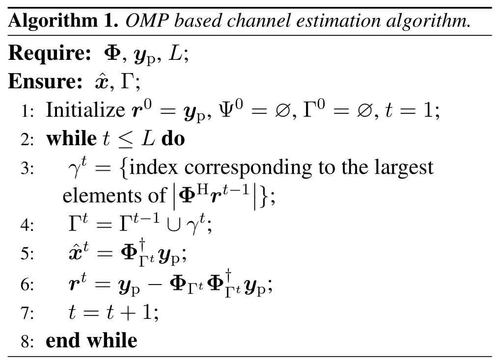
Considering the typicality and effectiveness,we leverage OMP algorithm to estimate the composed discrete-time CIRxby iteratively identifying the support set Γ consisting of the indices of the columns of sensing matrix Φ.The estimation process is then briefly demonstrated as follows:
1) Attth iteration,OMP selects an indexγtbased on a maximal correlation test(line 3).
2) The single candidate indexγtis added into the current support set Γt(line 4).
3) The channel is recovered by addressing the following problem,i.e.,=arg min||yp−ΦΓtx||22where ΦΓtis a submatrix whose columns are extracted from the sensing matrix with support set indices(line 5).

Algorithm 1.OMP based channel estimation algorithm.Require: Φ,yp,L;Ensure: ˆx,Γ;1: Initialize r0=yp,Ψ0=∅,Γ0=∅,t=1;2: while t ≤L do 3: γt={index corresponding to the largest elements of||ΦHrt−1||};4: Γt=Γt−1 ∪γt;5: ˆxt=Φ†Γtyp;6: rt=yp−ΦΓtΦ†Γtyp;7: t=t+1;8: end while
4) The residualrtis updated by subtracting the observationypfrom its orthogonal projection onto the subspace spanned by the columns in the support set Γt(line 6).
5) Iteration halts when theLindices are identified(line 2).
The pseudo-code of OMP based channel estimation is described in Algorithm 1.
IV.NUMERICAL RESULTS
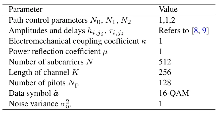
The goals of this subsection are two-fold:(i)depicting the profile of the composed discrete-time CIRx; (ii)investigating the performance of the OMP algorithm for estimatingx.In particular,two algorithms are considered for comparisons: (i)least square(LS);(ii)sparse bayesian learning (SBL) [17]with maximum iterations being 20.The parameters are summarized in Table 1.Simulation results are averaged over 103independent Monte Carlo simulations.The evaluation metric,i.e.,mean squared error (MSE),is defined as MSE=E(||xp−vp||22).

Table 1.Simulation parameters.
4.1 Channel Profiles
In Figure 4,the channel profiles are depicted under various PAB node states.The coordinates (x,y) (in meter)are as follows: S(0,4),N(5,0),R(8,2),surfacey=6,and bottomy=0.AssumingN0=1,N1=1 andN2=2,we calculate the theoretical path number(sparsity)of composed discrete-time CIR asL=L0+bL1L2=5 + (3×5)b.However,Figure 4 shows that the actual path number isL=Lh+bLg=5 + (1×4)b.In addition,from a physical point of view,it can be seen that reflective state results in a more harsh and severe propagation environment than unreflective state.
Figure 5 shows the CIRs.Compare Figure 5(a)and(b),we can see that the combined channel poses another four impulses on direct channel with relatively small amplitudes.This is due to the double attenuations of S−N,N−R links and severe attenuation in PAB node.It also worths noticed that the actual path number (sparsity) is far less than the theoretical one.The reason is twofold.First,the incident/transmission angles of certain paths(j1=0,1 andj2=0)are too large to meet the critical angle condition,making the signal impossible to get into the node.As mentioned in Remark 4,the backscatter coefficients related to these paths become zero and the number of effective paths decreases.For example,the effective path with non-zero backscattering coefficient consists ofj1=2 andj2=1,2,3,4 in Figure 4 (b).Second,the paths with identical distance(hence the delay)are combined into a single one.For example,pathsj0=±1 in Figure 4(a)are merged to form the second pulse in composed CIR in Figure 5.
4.2 Algorithm Performance
Figure 6 shows MSE versus signal-to-noise ratio(SNR)under distinct PAB node states.As can be seen from Figure 6 that the each MSE curve declines with the increase of SNR and both LS cases provide worse performance in contrast with OMP,which verifies the inadequacy of LS to solve an underdetermined equation.For LS and SBL algorithms,the curves onb=0 andb=1 show relatively small gaps,illustrating that channel sparsity has almost no effect on LS and SBL performances.However,an obvious gap occurs for OMP based algorithm.With the increase of channel sparsity,the percentage of path being estimated correctly decreases.This coordinates with the observation in[14].
Figure 7 shows the MSE versus the SNR.We assumeb=0 and different numbers of pilots are uniformly inserted into subcarriers.As the number of pilots increases,MSE decreases for all three algorithms.It is worth noting that the OMP algorithm achieves,in general,a better MSE performance than LS and SBL for the same number of pilots.In other words,for the same MSE level,the OMP algorithm uses fewer pilots than the competitors.
Figure 8 plots the CIR estimation performance in the unreflective state under the assumption ofb=0 and SNR=18 dB.The composed discrete-time CIR of LS approach is calculated asLS=(Fp)†.As can be seen from Figure 8 that,though recovery errors occur in two low-amplitude paths,the sparsity associated with the OMP algorithm shows highest similarity with original CIR,and the rest of the paths remain almost zero.However,the composed discretetime CIRs recovered by LS and SBL methods show remarkable differences from the original one.Most of the paths are constructed with small non-zero amplitudes.This demonstrates the limitation of LS approach on addressing the underdetermined equation.To sum up,the OMP based channel estimation algorithm outperforms the LS and SBL based channel estimation algorithms.
Figure 9 displays the running time for estimating CFR based on LS,OMP and SBL algorithms.It can be seen that the OMP time complexity intermediated between LS and SBL method,but gains from highest estimation accuracy.The reason is that OMP algorithm selects one index by solving one LS problem at a time,and the totalLindices need to be identified through subsequent iterations.For the extreme case of 1-sparse channel,OMP algorithm may offer comparable time complexity compared with LS approach.While SBL algorithm tries to estimate the channel blindly until reaching finite maximum iterations.In other words,SBL algorithm may provide the best performance without considering the time cost in some cases.
V.CONCLUSION
In this paper,we have provided a theoretical framework of the PAB assisted UWA communication systems for the first time.Based on this framework,we addressed the channel estimation problem employing the CS theory.More concretely,we presented the five-stage backscatter process and derived the corresponding backscatter coefficient.The parameters to be estimated were then developed following the description of shallow-water acoustic channels.We next formulated the shallow-water acoustic channel estimation problem as a sparse vector recovery problem and leveraged the OMP algorithm to solve it.Numerical results demonstrated that the proposed OMP algorithm outperforms the LS and SBL competitors in estimation accuracy and complexity,respectively.
ACKNOWLEDGEMENT
This work was supported by National Key Research and Development Program of China(2020YFB1806604,2021YFB3901302) and National Natural Science Foundation of China (No.61871026).
- China Communications的其它文章
- Environment Information-Based Channel Prediction Method Assisted by Graph Neural Network
- Multi-Scenario Millimeter Wave Wireless Channel Measurements and Sparsity Analysis
- AG Channel Measurements and Characteristics Analysis in Hilly Scenarios for 6G UAV Communications
- Long-Range VNA-Based Channel Sounder: Design and Measurement Validation at MmWave and Sub-THz Frequency Bands
- A Novel Millimeter-Wave Channel Measurement Platform for 6G Intelligent Railway Scenarios
- A Geometry-Based Stochastic Scattering Channel Model for V2V Communications in Dense Urban Street Environments

