A Novel Millimeter-Wave Channel Measurement Platform for 6G Intelligent Railway Scenarios
Dan Fei,Chen Chen,Peng Zheng,Dongsheng Zhang,Jingya Yang,Haoran Chen,Bo Ai,6
1 School of Electronic and Information Engineering,Beijing Jiaotong University,Beijing 100044,China
2 State Key Laboratory of Rail Traffic Control and Safety,Beijing Jiaotong University,Beijing 100044,China
3 Collaborative Innovation Center of Railway Traffic Safety,Beijing Jiaotong University,Beijing 100044,China
4 Frontiers Science Center for Smart High-speed Railway System,Beijing Jiaotong University,Beijing 100044,China
5 Zhengzhou Railway Vocational and Technical College,Zhengzhou 451460,China
6 Peng Cheng Laboratory,Shenzhen 518055,China
Abstract: This paper presented a novel millimeterwave channel measurement platform for the 6G intelligent railway.This platform used phased array antenna with 64 elements and can support instant bandwidth up to 1 GHz.Combined with improved multi-tone sounding signals,the platform can enhance dynamic measurement capability in high-speed railway scenarios.We performed calibration works about frequency flatness,frequency offset and proved platform reliability with channel emulator based closed-loop verification.We also carried out field trials in high-speed railway carriage scenarios.Based on measurement results,we extracted channel characteristic parameters of path loss,power delay profile and delay spread to further verify the field measurement performance of the platform.
Keywords: 6G; millimeter-wave; channel measurement;phased array antenna;high-speed railway
I.INTRODUCTION
Countries around the world have started the sixthgeneration (6G) mobile communication systemrelated research,and it is expected that the 6G system will be realized by 2030 [1].The 6G mobile communication system will integrate terrestrial wireless and satellite communication,and it can help to break the limitations of network capacity and transmission rate,which achieve the goal of interconnecting everything.With the expansion of 6G technology to full-band,full-scenario,and full-coverage dimensions,6G intelligent wireless railway communication scenarios will show a trend of more diversification and complexity [2,3].The 6G intelligent wireless railway communication system will cover high frequency bands,such as millimeter-wave(mmWave)communications.MmWave communication can provide higher bandwidth and transmission rate for railway wireless communication systems[4].However,high-frequency communication will bring serious propagation Loss and severe Doppler effect.As a result,the channel changes significantly,and the non-stationary features are prominent,which will bring new challenges to the research of channel measurement and modeling.In addition,in the 6G smart transportation,domestic and foreign universities and research institutions have also proposed a variety of technical solutions.
Wireless channel measurement can help to extract channel parameters and provide essential references for subsequent channel modeling and standardization work.MmWave communication will be used in the 6G intelligent wireless railway communication,and thus there are more strict requirements for measurement instruments in terms of wide bandwidth and high frequency.Traditional mobile communication systems work in frequencies below 6 GHz,and a large number of channel model research results have been accumulated in the Sub6G band.There are some researches on mmwave channel propagation characteristics in public network scenarios,but few in high-speed railway or other highly dynamic scenarios.Hence,it is necessary to further improve the channel measurement methods for highly dynamic channel characteristic parameters extraction and modeling.[5]
The high-frequency channel measurement and research have a history of more than 20 years.The channel characteristics have gradually transitioned from the early narrowband characteristics to the broadband characteristics.Corresponding small-scale characteristics have developed from the single delay domain multipath characteristics to Delay-direction domain joint features.Channel measurement in mmWave has attracted significant interest in recent years from both academia and industry,and many research groups have carried out related works.Some large international communication companies,universities,and research institutes have carried out a large number of channel measurement studies in different frequency bands,including the teams of Professor T.S.Rappaport [6],Japanese National Institute of Information and Communications Technology (NICT),Intel Labs(Russia and Germany),Fraunhofer HHI Laboratory,Aalto University,Tokyo Institute of Technology,etc.Several influential international project groups,such as METIS[7],MiWEBA[8],mmMAGIC[9],5GCM[10],etc.,are formed for wireless channel standardization work.IEEE802.153c channel model is completed by Japanese NICT[11],Australian NICTA,Germany IMST,France Telecom(FT),IBM,etc[12].The team of Prof.Rappaport used separate components and modules to independently build a wideband detector based on sliding correlation[13]with chip rates ranging from 200 MHz,400 MHz to 750 MHz (the frequency width from zero to zero is equal to twice the chip rate),and successively conducted measurement activities in the 28 GHz,38 GHz,60 GHz and 73.5 GHz frequency bands at Virginia Tech (VT),University of Texas at Austin (UT-Austin) and New York University (NYU)[14].Alfred Mudonhi’s team carried out the mmwave channel sounding enabled by reconfigurable intelligent surfaces(RISs).The measurement setup is based on an electronically Transmitting-RIS (T-RIS) composed of 400 unit cells [15].Optimal phase distributions were implemented in order to operate a beam scan over 120 degrees.Two indoor scenarios were investigated in the Ka-Band,exploiting the beam scanning capabilities of the antenna.The results in terms of path loss and delay spread are presented and discussed.Ref.[16]proposed a novel real time MIMO sounder of 28 GHz based on phased array antenna,the mentioned platform realized channel measurement in dynamic environment with short measurement time.
The mmwave channel measurement platform proposed in this paper adopted the vector signal structure with flexibly configurable sampling rate and signal bandwidth.The transmitter is equipped with a high gain phased array antenna,which can complete ±55 degrees beam scanning with switching speed within less than 10us,ensuring the measurement distance and speed in high-speed railway scenarios.The receiver is equipped with a 4-element antenna array to complete the 4-channel parallel signal reception so that it can fast capture the high dynamic channel data in high-speed scenarios.This platform can support channel measurement from 10 MHz to 26.5GHz with maximal analyzing bandwidth of 400 MHz.It can steam all baseband signals to disk for storage continuously with partial data processed in real time,which is very important for measurement status monitoring in dynamic measurements.
The rest of this paper is organized as follows: Section II introduced system architecture and gave a brief description about the sounding waveform,data processing,and related antenna array.Section III introduces a specific synchronization scheme for the measurement platform and performs related calibration work for better performance.Section IV verified accuracy of the measurement platform by labratory closeloop work and filed trials in Fuxing CR.Based on measurement results,we evaluated the performance features of path loss,multi-path,delay spread,etc.Section V concluded this paper generally and then provided suggestions for further research.
II.SYSTEM DESCRIPTION
2.1 Structure of System
The structure of this platform is shown in Figure 1.The transmitter and receiver are mainly composed of a baseband signal generator,a up-converter,a downconverter,a wideband digitizer,and phased array antenna.The Tx side and Rx side can complete high precision reference clock synchronization and local oscillator synchronization through a GPS clock timing module.Triggered by a pulse generator,the absolute delay of radio wave propagation can be measured.
The transceiver adapted an independent hardware structure with instant bandwidth up to 1 GHz at center frequency of 26 GHz.Both the transmitter and receiver are equipped with high precision synchronization and triggering modules.The system can use different synchronization and triggering modes to meet the channel measurement requirements in different scenarios (indoor and outdoor).With the help of a baseband signal generator,the transmitter can generate sounding signals in the form of differential signals.Through an up-converter and radio amplifier,the transmitter can generate RF signal with power of 17 dBm at frequency of 26 GHz.The phased array antenna with a 64-element can further amplify the power to more than 50 dBm and complete the high-speed beam scanning.RF signal captured by 4-elements antenna array can be processed in 4-channel high-speed digitizers through a 4-channel down-converter.After that,the high-speed data can be streamed to disk array in real time.The system synchronization performance can be ensured by high precision rubidium clock with a GPS timing function.
2.2 Sounding Waveform
Considering the excellent flatness performance in frequency domain and similarity to orthogonal frequency division multiplexing(OFDM)adopted by 4G and 5G,the multi-tone signal is chosen as sounding waveform,which can be expressed as(In this formula,∆fmeans subcarrier gap andθnmeans phase value of each subcarrier)
For multi-tone signals,smaller subcarrier spacing can improve the measurement resolution in the frequency domain under the premise of ensuring orthogonality.Generally,sampling rateFs,sampling pointsNand subcarrier spacing ∆fmeet the mathematic relationship below:
Therefore,in the case of wide measurement bandwidth for mmwave channel,Fsis large,which will lead to large ∆fwhenNis fixed.So,increasingNis the only way to decrease ∆f,but largerNwill lead to longer length of each snapshot,thus reducing the capability of dynamic measurement for doppler effect.This paper put forward an improved multi-tone signal that can decrease subcarrier spacing without sampling pointsNand snapshot length changed.As Figure 2 shown,the main idea is to superpose multiple multitone signals in time domain with fixed frequency offset so that the blank frequency of the original signal can be supplemented at equal subcarrier spacing.foffstands for frequency offset of sounding signal,then the improved sounding signal with frequency offsetsoff(t)andsadd(t)can be written as
After the simulation,the improved multi-tone signal still has a relatively low peak-to-average power ratio.At the same time,it overcomes the defects of the original multi-tone signal in the high-speed moving scenarios.
2.3 Data Processing
The structure of data processing at receiver is shown in Figure 3.After the signal is collected by the digitizer,it can be transferred to the upper controller at high speed.Due to the large bandwidth of the millimeter wave channel measurement system,the host computer needs to process a massive amount of data fast enough.Therefore,it is necessary to design efficient parallel data processing system.
The program is run in the form of data flow.The movement of data through nodes determines the order in which functions on the block diagram are executed.If the signal acquisition,signal processing,and data storage are processed sequentially,the vast amount of data and processing process will significantly limit the length of data acquisition.This requires the data processing software to work in parallel,which can be achieved by using queue structure,as shown in Figure 3.The software needs to collect and save all the data in a real time cycle,transfer part of the data into the queue,then read the queue in another cycle and display the received IQ waveform,frequency domain signal,and power delay spectrum after digital up-conversion.It is worth noting that the data should be bound with GPS information when saving the data for post processing,and this method is very important for channel measurement in high-speed railway scenarios.This paper adopts an asynchronous storage scheme to save data in the Technical Data Management Stream(TDMS)file management format,which supports high-speed data streaming.
2.4 Phased Array Antennas
As Figure 4 shows,the phased array antenna structure is mainly composed of main functional modules such
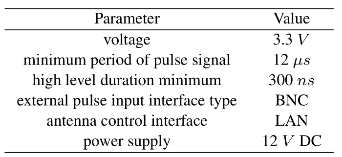
as planar antenna array,phase shifter,wave controller,and central controller.The phased array antenna has 64 elements,and the number of array elements in each dimension is 8.It can realize beam scanning with the range of ±60° in two dimensions.The operating frequency of phase array antenna is from 24.25 GHz to 27.5 GHz,and the emission equivalent isotropically radiated power(EIRP)can reach 50 dBm which is strong enough for long distance coverage in highspeed raliway scenarios.The beam width is 13° and the minimum beam switching time can reach 12us.The main parameters of phased array antenna pulse control module are listed in Table 1.

Table 1.Parameters of phased array antenna pulse control module.
The host controller and the phased array antenna can realize communication through ethernet port.The pulse control interface type is BNC,the pulse signal period should be greater than 12µs,and the level should be 3.3V.The pulse signal is generated by the digital IO of the digitizer at the receiving end.When the phased array antenna is set in the pulse control mode,the beam direction can be changed based on the programmed codebook once receiving a pulse level signal.
III.SYNCHRONIZATION AND CALIBRATION
In this section,we introduced the system synchronization and calibration methods.Precise synchronization and reasonable calibration work can improve system accuracy,which is helpful to further Channel Impulse Response(CIR)extraction and performance analysis.
3.1 Synchronization Scheme
Transmitter and receiver of channel measurement should take the same clock source as reference.The shared clock source can guarantee frequency and phase coherence of sampling clock.Otherwise,it will bring measurement errors which will result in incorrect channel information,especially in high-speed mobile scenarios.For general mmwave channel measurement platform,shared clock reference by cable is commonly used.But in railway long distance channel measurement,GPS clock reference is more feasible and effective.
Reference clocks sharing with cable and GPS are both realized in this system,as Figure 5 shown.For the cable case,the master-slave clock source mode is used.All the baseband clock,sampling clock,and local oscillator shared the same reference source from transmitter to receiver by cable,or vice versa.For the GPS case,it used GPS mode.Both transmitter and receiver are equipped with high precision rubidium clock with reference of GPS clock source.Regrad to two reference clock source modes,we also conducted corresponding experiments to validate accuracy and reliability.
3.2 Frequency Flatness Calibration
In the channel measurement system,the frequency domain flatness is an important criterion to evaluate received signal quality.Frequency domain flatness of received signal is mainly affected by the actual hardware performance.Therefore the flatness correction can help to overcome the influence of hardware limitation.As Figure 6 shown,it depicted the principle of flatness calibration.
Figure 7 displayed the received signal spectrum comparison before and after calibration,and it is observed that frequency flatness was improved after proper calibration.
3.3 Back to Back Calibration
Generally,it is required to execute Back-to-Back(B2B) calibration before channel measurement trials.B2B calibration can help to eliminate frequency response errors of devices.Channel measurement in mmWave band has strict requirements for device stability such as up-convertor,down-convertor,radio amplifier,etc.In order to eliminate self influence of the platform,it is necessary to execute B2B calibration work before each measurement.As Figure 8 shows,we replaced antenna and wireless channel with attenuator,then connected the transmitter with receiver through an attenuator with a specific value of 60 dB.The collected B2B data can be used as calibration reference.
After proper B2B calibration,the channel transfer function of millimeter channel measurement met the ideal condition which has constant value of 1.As Figure 9 shows,the slope of the phase-frequency response function expressed the value of cluster delay.The rootmean-square-error (RMSE) of channel transfer function amplitude-frequency response is about 0.16 dB and the RMSE of phase-frequency response is about 2.9 degree.As a result,B2B calibration can eliminate self response of devices.
3.4 Frequency Offset Calibration
In high-speed railway scenarios,wireless channel commonly has time-varying property.Typically,the separation of transmitter and receiver will have carrier frequency offset(CFO)which introduce uncertain impact on system.As Figure 10 shows,CFO with valueεwill introduce frequency offset,which further results in Inter-Carrier interference(ICI)[17].As a result,it is necessary to correctly estimate and calibrate the frequency offset for better measurement accuracy[18].During the channel measurement process,the same sounding signal is continuously sent for channel measurement.For two consecutive identical probing signals,the response relationship between the two received signals in frequency domain has the following relationship(εstands for the carrier frequency offset)
Y1[n]andY2[n]are previous signal and latter signal respectively,andnstands for the sampling points.Using the relationship of the above formula,the CFO can be estimated as
This method is proposed by Moose[19]which can help to estimate carrier frequency difference.The signal after frequency offset correctionYcal[n]can be expressed as below: (Yori[n]stands for frequency domain signal before calibration)
As Figure 11 shown,it compared the normalized power delay spectrum with and without frequency offset calibration.It is obvious that carrier frequency offset will raise noise around main path and further affect dynamic measurement range and resolution of multipath.
IV.MEASUREMENT AND PERFORMANCE VERIFICATION
This measurement platform mainly focuses on path loss and multi-path effect which is closed to the highspeed railway scenarios.Section III has concluded calibration works for this platform,and this part will introduce corresponding measurement work and verification results.In this section,we performed verification work about path loss,PDP,etc.Then,we carried out field trials in practical high-speed railway carriage.
4.0.1 Path Loss Verification
Based on previous B2B calibration work,our measurement platform can eliminate devices’ self response.In order to evaluate accuracy in large scale fading,we carried out pathloss verification work.
Similar to B2B calibration connection,we add another attenuator with determined value between transmitter and receiver,as Figure 12 is shown.
During the whole process,all modules are connected through RF cables so that we can directly received correct signal without distortion.Based on saved IQ data,we can calculate channel impulse response and then extract related pathloss value(see Figure 13).The verification results showed that measured pathloss value is about−30.0048 dB which matched with value of determined attenuator.
4.1 PDP Verification
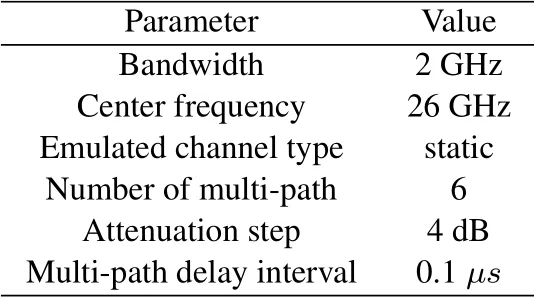
In order to evaluate the reliability of the system,we performed various verification works.This subsection will introduce a laboratory closed-loop verification work with the help of channel emulator.As shown in Figure 14,transmitter transmitted sounding signal and receiver received signal through emulated channel and stored IQ data in time.The detailed channel parameters are shown in Table 2,and it emulated 6 multi-path with 4 dB attenuated in turn and the uniform delay interval between each adjacent path was set as 0.1us.

Table 2.The simulation value.
Figure 15 depicted the verification results of emulated channel measurement.The power delay spectrum shows that the attenuation of configured six multi-paths’power is from 0 dB to 20 dB respectively and corresponding delay of each propagation path is from 0nsto 500ns.The results proved the accuracy of the mmwave platform in multi-path measurement.
4.2 Phase Coherence Verification
In this paper,the receiver contains a four-channel parallel structure with a multi-channel radio frequency link,and thus it is necessary to guarantee the phase consistency among different channel.By building up a multi-channel phase consistency test system as shown in Figure 16,multi-channel signal superposition is realized and related analysis among channels is performed.Phase coherence verification work provided a basis for the further application of angle estimation algorithms.
As Figure 17 shown,the initial phases of each channel are all consistent and related power also fits with set parameters in intermediate frequency (IF) signal amplifier.Therefore,the multi-channel receiving system has good phase consistency.
4.3 Field Trials Measurement
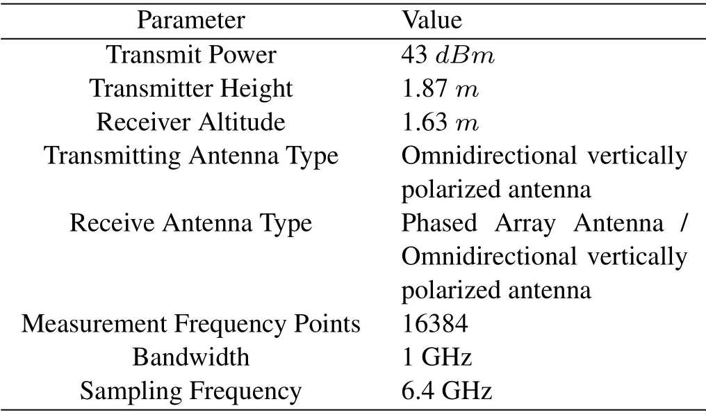
4.3.1 Measurement Scenarios To analyze practical wireless channel of high-speed railway scenarios,we performed field trials in Fuxing China Rejuvenation (CR) which is a new generation of high-speed trains independently developed by China.In the practical scenarios of train carriage,we used different combinations of tx and rx antennas.As Figure 18 shown,the blue mark represents the position of tx antenna which is omnidirectional vertically polarized.The red straight line represents measurement trace of the receiver,but the red dots represent fixed measurement point when receiving antenna is replaced by phased array.The scanning mode of phased array antenna was set as: pitch angle fixed as 0°,azimuth angle scanned from−45°to 45°in steps of 5°.
Tx antenna was fixed at the roof ventilation fence,Rx antenna was installed on a tripod,and the setup scenario of Tx and Rx antennas is shown in Figure 19.Figure 19(a) showed the layout when receiving antenna is a phased array and Figure 19(b) showed the layout when receiving antenna is an omnidirectional antenna.Detailed parameters are shown in Table 3.

Table 3.Measurement parameter in the Fuxing CR.
4.3.2 Path Loss Analysis
The path loss fitness and analysis of the LoS case and the NLoS case in Fuxing CR field trials is shown in Figure 20 and the detailed parameters of each fitting model are shown in Table 4.

Table 4.Comparison of path Loss parameters in LoS and NLoS cases.
Based on measurement results,it is observed that the PLE value is greatly affected by penetration loss and the propagation environment.In NLoS communication case,PLE is worse than that in the LoS case.
4.3.3 Power Delay Profile Analysis
The PDP of the NLoS case and the LoS case is shown in Figure 21.
It can be observed that delay of each propagation path mainly is located in the time range of 0-500ns.With the reference to experimental scenarios,the measured results fit with actual propagation time.
Due to the complex reflection and scattering environment in practical scenarios,there are many other arrived waves affecting the main path.To further analyze the statistical characteristic of multipaths,we showed the delay spread of multipath in Figure 22.The received signal delay spread in LoS case is mainly concentrated around 100nsand that in NLoS case commonly concentrated around 120ns.
V.CONCLUSION
In this paper,we presented a novel millimeter-wave channel measurement platform for high-speed railway,which can meet the demand of high-speed railway channel measurement in high dynamic scenarios.In this platform,we proposed an improved multitone waveform as sounding signal to improve the dynamic channel measurement capability,which is realized by superposition of the original signal with equal interval frequency shift.By introducing high gain phased array antenna and efficient beam scanning control method,we have realized the long distance coverage of millimeter wave band,meeting the channel measurement requirements of high-speed railway in open macro cellular scenario.Based on the platform,we performed calibration works about absolute power,flatness,frequency offset and proved platform reliability with closed-loop verification.With the help of this platform,we carried out field trials in high-speed railway train carriages scenarios.Based on measurement results,we extracted channel characteristic parameters of large-scale fading and small-scale fading,which can provide reference for future high-speed moving scenario measurement.
ACKNOWLEDGEMENT
This work was supported in part by the Fundamental Research Funds for the Central Universities under Grant 2022JBQY004,2022JBZY018 and 2022JBXT001,in part by the Basic Research Project of Jiangsu Province Frontier Leading Technology under Grant BK20212002.
- China Communications的其它文章
- Environment Information-Based Channel Prediction Method Assisted by Graph Neural Network
- Multi-Scenario Millimeter Wave Wireless Channel Measurements and Sparsity Analysis
- AG Channel Measurements and Characteristics Analysis in Hilly Scenarios for 6G UAV Communications
- Long-Range VNA-Based Channel Sounder: Design and Measurement Validation at MmWave and Sub-THz Frequency Bands
- A Geometry-Based Stochastic Scattering Channel Model for V2V Communications in Dense Urban Street Environments
- UWB Channel Modeling and Simulation with Continuous Frequency Response

