Frequency Regulation of Power Systems With a Wind Farm by Sliding-Mode-Based Design
Zhiwen Deng and Chang Xu
Abstract—Load frequency regulation is an essential auxiliary service used in dealing with the challenge of frequency stability in power systems that utilize an increasing proportion of wind power. We investigate a load frequency control method for multiarea interconnected power systems integrated with wind farms,aimed to eliminate the frequency deviation in each area and the tie-line power deviation between different areas. The method explores the derivative and integral terminal sliding mode control technology to solve the problem of load frequency regulation.Such technology employs the concept of relative degrees. However, the subsystems of wind-integrated interconnected power systems have different relative degrees, complicating the control design. This study develops the derivative and integral terminal sliding-mode-based controllers for these subsystems, realizing the load frequency regulation. Meanwhile, closed-loop stability is guaranteed with the theory of Lyapunov stability. Moreover, both a thermal power system and a wind power system are applied to provide frequency support in this study. Considering both constant and variable external disturbances, several numerical simulations were carried out in a two-area thermal power system with a wind farm. The results demonstrate the validity and feasibility of the developed method.
I. INTRODUCTION
WITH the increasing depletion of conventional fossil fuels, renewable energy technologies, that provide both sustainability and environmental friendliness, have drawn great attention and have been rapidly developed for several decades. Among them, wind power is one of the most promising technologies. Increasingly more electricity from wind farms has been generated in the last decade, making more of a contribution in the overall power system.
The rising proportion of wind power affects the frequency stability and the operation of power systems to some extent due to some unique features of wind power technology[1]–[3]. Firstly, the randomness and fluctuation of wind energy increases the frequency variations of wind-integrated power systems [4]. Secondly, variable speed wind turbines(VSWTs) have been widely utilized in power systems.VSWTs could reduce the inertia of power systems and result in more severe frequency fluctuations once load variations rise up [5], [6]. Thirdly, the replacement of conventional power generators (e.g., thermal and hydroelectric generators) by wind generators reduces the frequency regulation capability of power systems because of an increase of the regulation constant [3]. However, the VSWTs respond faster in power regulation than conventional power generators [7], [8]. Thus the control methods of VSWTs via inertial emulation control,droop control, deloading control and over-production control have been investigated extensively for the purpose of frequency support in wind-integrated power systems [9]–[11].
Load frequency control (LFC) is an essential auxiliary service to ensure the safety and stability of power systems. For a multi-area interconnected power system [12], the objective of LFC is to balance the load and power generation in all control areas, eliminating the frequency deviations and the tie-line power deviations between different areas [13]. Many methods concerning the LFC problem have been reported such as the integral-based distributed control method [14], the direct-indirect adaptive fuzzy control technique [15], the decentralized resilientH∞method [16], and so forth. Recently, the increasing impact of wind power on power systems has drawn great attention. A coordinated approach was designed through the zero dynamics technique for large-scale power systems in[17], which aimed to improve the transient stability of largescale power systems including wind power systems. The model identification adaptive PID controller in [18] was designed for the LFC of wind-integrated power systems. The cascaded PID controller was designed in [19] for a power system with diverse power sources including wind turbines.However, improving the robustness of the controllers is required due to the uncertainty of wind energy.
Considering wind-integrated power systems, both uncertainties from wind speed and disturbances from load highlight the LFC problem of such power systems substantially. One possible solution to this problem is the control design. The sliding mode control (SMC) methodology is a powerful tool, known for its invariance to system uncertainties and disturbances[20]–[22], which is a potential solution for the LFC problem.Some SMC-based methods have been applied in practice such as the adaptive SMC method [23], the full-order SMC method[24], the nonlinear SMC method [25], and the linear SMC method [26]. At the same time, the impact of renewable energy, especially wind power, has also gotten a lot of attention. In order to regulate the frequency and voltage of an isolated wind-diesel hybrid power system, an adaptive SMC method was developed in [27]. A neural-network-based integral sliding mode controller (NNB I-SMC) was employed in a multi-area interconnected power system integrated with wind farms in [28]. A nonlinear SMC method for the LFC problem of a wind-integrated power system was proposed in [29]. Considering the disturbance induced by integrated renewable energies, a robustH∞sliding mode LFC method for multi-area power systems with time delay was investigated in [30].
Compared with other types of LFC methods, the SMCbased LFC methods exhibit stronger robustness. Furthermore,the terminal SMC technology has been utilized for frequency regulation, aiming to guarantee a system with finite-time convergence [2], [31]. Up to now, however, far too little attention has been paid to deal with the singularity problem existing in the LFC based on the terminal SMC technology. In [32], a unified dynamic terminal SMC technology known as the derivative and integral terminal SMC technology was proposed for a class of systems with different relative degrees.Such technology guarantees the system with finite-time convergence and avoids the singularity problem during the control design process. Moreover, it exhibits superior control properties and robustness performance in terms of system uncertainties and external disturbances. Consequently, this study proposes an LFC method for wind-integrated power systems based on the derivative and integral terminal SMC technology.
Additionally, we apply both the thermal generators and wind generators in a wind-integrated power system to provide frequency support. To this end, a wind power system model based on the mechanical dynamics of VSWTs is utilized,which allows the wind power system to flexibly participate in the frequency regulation of the wind-integrated power system.
The remaining part of this paper proceeds as below. In Section II, the models of a thermal power system, a VSWT system and a wind-integrated two-area thermal power system are established and briefly described. In Section III, the controllers are designed for the wind-integrated two-area thermal power system. In Section IV, the control performance of the proposed frequency control method is analyzed by numerical simulations. In Section V, some conclusions are presented eventually.
II. SYSTEM CONFIGURATION
This section first illustrates the system modeling of a single power system and a VSWT system, then, the compositions of a wind-integrated two-area thermal power system.
A. Power System
A power system usually consists of multiple control areas interconnected by tie lines. Fig. 1 shows the linearized model of thenth control area of the power system withNareas. It mainly contains a governor, a turbine and the rotating mass and load, which are defined as below [28]:

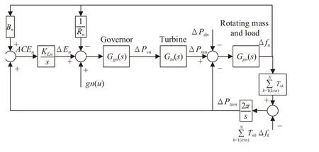
Fig. 1. Model of the nth control area.

where Δfn(t), ΔPmn(t), ΔEn(t), ΔPtien(t), and ΔPvn(t) are the system states representing the deviations of frequency (Hz), generator output (p.u.MW), integral control (p.u.MW), tie-line power flow (p.u.MW), and governor valve position (p.u.MW),respectively. ΔPdn(t) is the load disturbance (p.u.MW).Kpn,Rn,KEn, andBnare the power system gain (Hz/p.u.MW), the speed regulation coefficient (Hz/p.u.MW), the integral control gain (Hz/p.u.MW), and the frequency bias factor(Hz/p.u.MW), respectively.Tnkis the interconnection tie-line gain (p.u.MW/rad/s) between thenth andkth area.uis the system input vector.gn(u) is a function of the system inputs.
B. Wind Power System
Wind energy is converted into mechanical torque by the aerodynamic components of the wind power system. Then, the torque is transmitted to the generator by the drive train. The generator converts the torque into electricity and finally outputs it to the power system. Under the ideal condition of neglecting mechanical and electromagnetic losses, the mechanical power of the wind turbine is regarded as the power output to the power system when the wind power system is operating stably. Based on the ideal condition, a simplified VSWT model is applied here as a wind power system. As shown in Fig. 2, it mainly consists of an aerodynamic model and a drive train model. The aerodynamic model is based on theCp(λ,β)curve of the wind turbine as below:


Fig. 2. Wind power system.
C. Wind-Integrated Two-Area Thermal Power System
The proposed control method is implemented in a windintegrated two-area thermal power system. Based on the models of the single area power system and the wind power system, the wind-integrated two-area thermal power system is finally established. As shown in Fig. 3, the wind power system is integrated into Area-1. The droop control method and

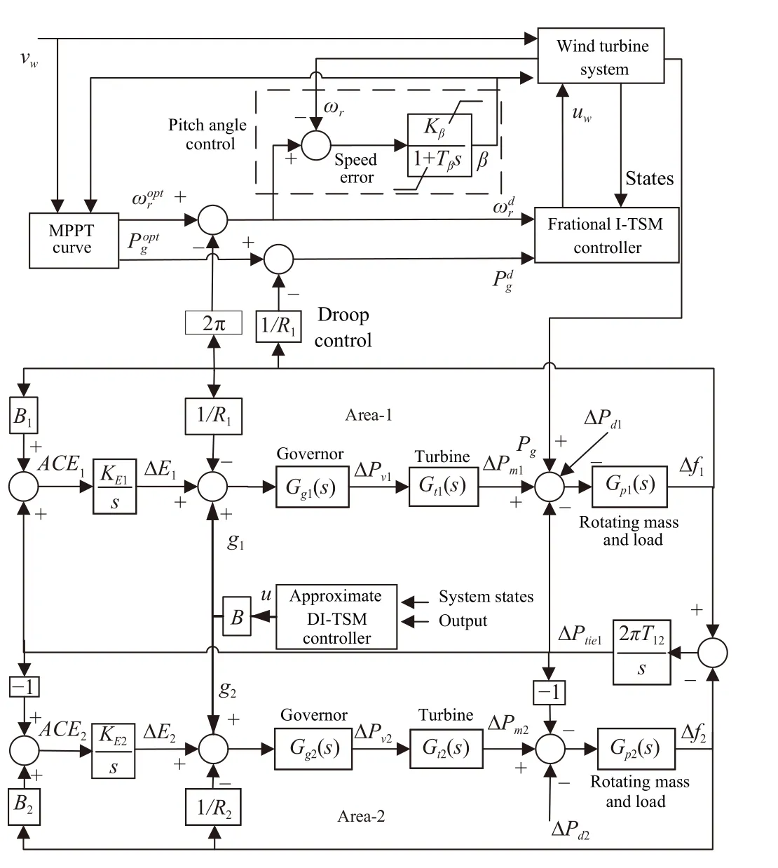
Fig. 3. Wind-integrated two-area thermal power system.
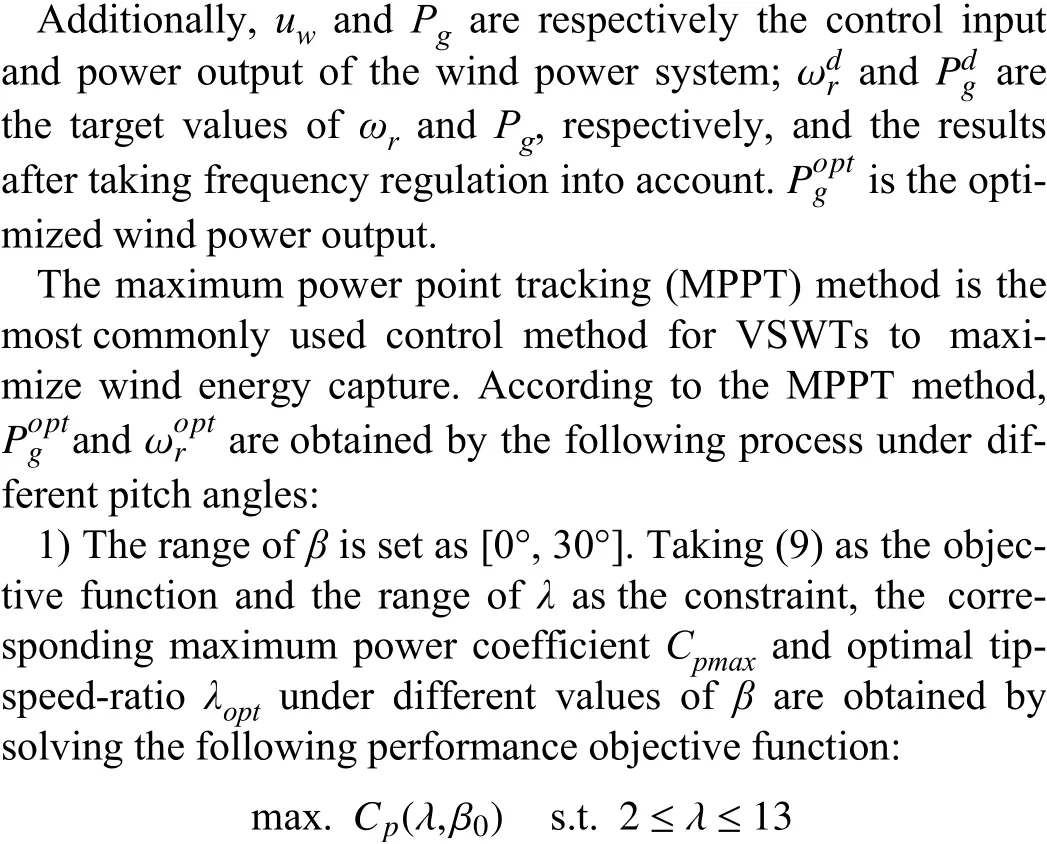
whereβ0is a concrete value between 0° and 30°. The constraint condition aboutλis determined by the operation of the wind turbine. By this approach, the performance curves ofCpmaxandλoptwith respect toβare obtained (illustrated in Fig. 4).
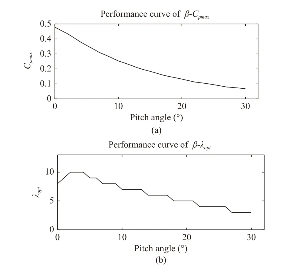
Fig. 4. Performance curves for MPPT (a) β-Cpmax curve; (b) β-λopt curve.
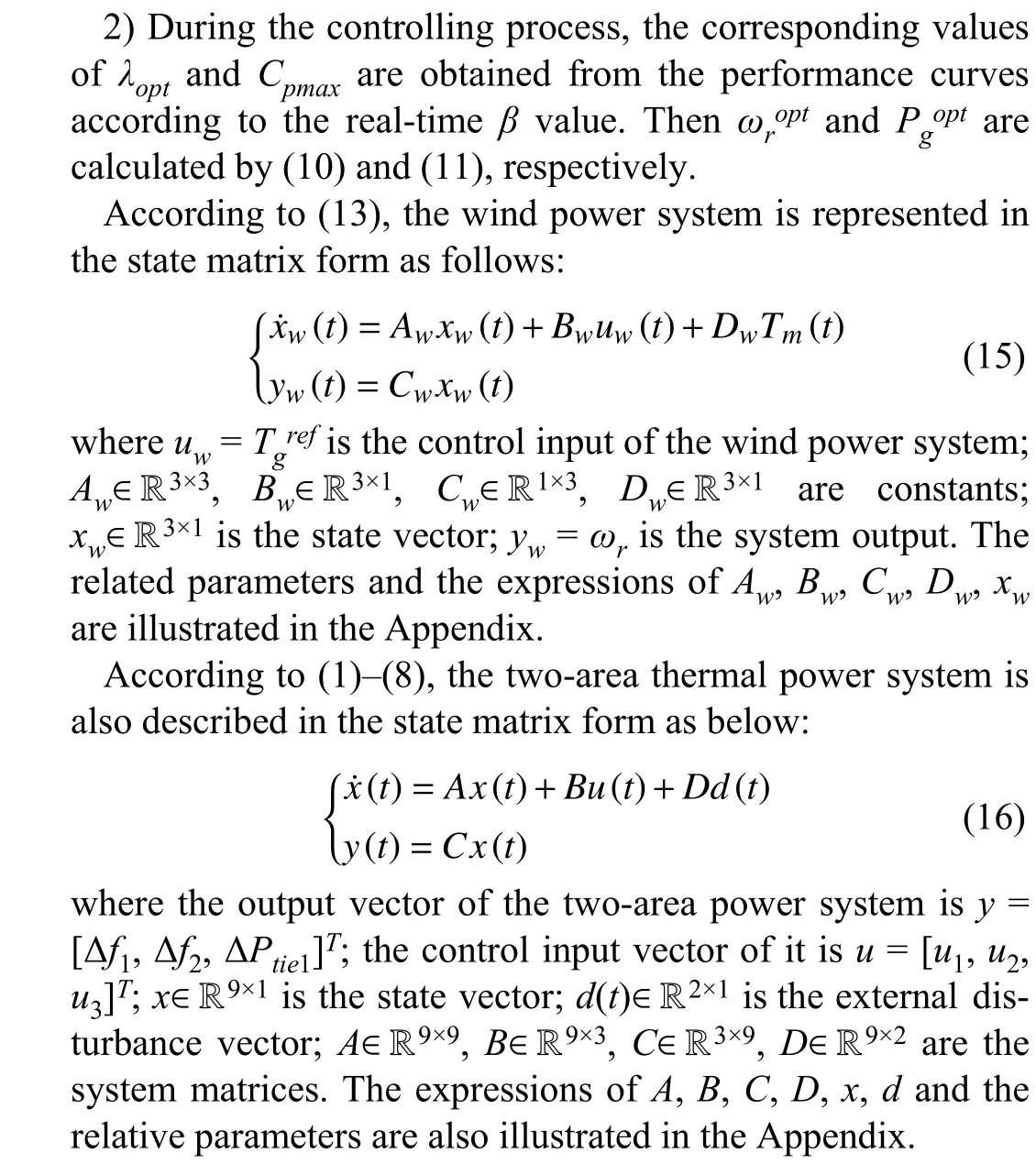
III. CONTROL DESIGN
This section describes the process of designing controllers for the wind-integrated two-area thermal power system based on the derivative and integral terminal SMC technology. The controllers of the two-area thermal power system and the wind power system are designed independently.
According to the definition of the derivative and integral terminal SMC technology, the fractional integral terminal sliding mode control (fractional I-TSMC) method and the approximate derivative-integral terminal sliding mode control(approximate DI-TSMC) method are generated for systems with different relative degrees. The fractional I-TSMC method is designed for the output tracking of relative-degree-one systems. While for high relative degree systems (systems with at least one relative degree greater than 1), the fractional ITSMC method is extended and simplified to the approximate DI-TSMC method for good convergence and easy implementation [32]. Therefore, the control design in each subsystem should be on the basis of its relative degrees.
A. Control Design For the Two-Area Thermal Power System
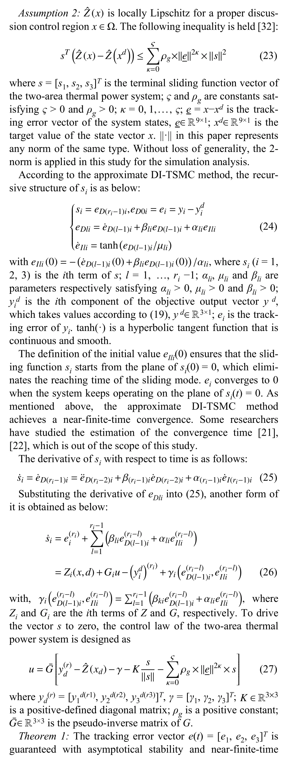
The two-area thermal power system of (16) is changed into the following form for convenience:


B. Control Design for the Wind Power System
Similar to (17), the wind power system of (15) is also changed into the following form:

whereZwandGware constants directly defined in (30).Zwdoes not contain the disturbance term.


IV. NUMERICAL SIMULATION
To evaluate the effectiveness of the proposed control method, corresponding numerical simulations are carried out on the wind-integrated two-area thermal power system. The parameters of the wind power system controller are set asq=13,p= 15,α= 2,δw= 2,Kw= 0.15,ρw= 300,Lw= 10,ς= 1.The parameters of the two-area thermal power system controller are set asβ11=β12=β13=β21=β22=β23=β33= 15,α11=α12=α13=α21=α22=α23=α33= 8,μ11=μ12=μ13=μ21=μ22=μ23=μ33= 0.1,K= diag(50, 50,300),ρg= 0.2,L= 10.
A. Comparisons
For the first simulation experiment, comparisons among the LFC method proposed in this study and the LFC methods based on the nonlinear SMC method [29] and the NNB I-SMC method [28] are carried out.
For comparison, the wind speed and load disturbances are set to be the same constants under different LFC methods. The wind speed of the wind power system is set tovw= 10 m/s,and the load disturbances of the two-area thermal power system are set to ΔPd1= 0.01 and ΔPd2= 0.01, respectively.
The simulation results of the three methods are displayed in Fig. 5. Fig. 5(a) shows the responses of the power outputPgof the wind power system under the three methods. ThoughPgconverges stably under different methods, it converges significantly faster by applying the proposed method. Figs. 5(b),5(c), and 5(d) exhibit the responses of Δf1, Δf2, and ΔPtie1of the two-area thermal power system, respectively. The nadir of the dot-dash line in Fig. 5(b) is -1.84×10⁻³Hz at 0.38 s and that of the dot-dash line in Fig. 5(c) is -1.91×10⁻³Hz at 0.49 s. To compare the responses of Δf1and Δf2more clearly,Figs. 5(b) and 5(c) only show the signals in the ordinate range from -2×10⁻⁴Hz to 2×10⁻⁴Hz. Δf1, Δf2, and ΔPtie1converge to 0 in the shortest time under the LFC method proposed in this study. Moreover, the oscillations under the proposed method are significantly smaller than those under the other two methods. Thus, the LFC method proposed in this study have better effectiveness in solving the LFC problem of the wind-integrated power system.

Fig. 5. Response comparison between the proposed LFC method, the nonlinear SMC-based method and the NNB I-SMC-based method (a) Power output of the wind power system Pg; (b) Frequency deviation Δf1; (c) Frequency deviation Δf2; (d) Deviation of tie-line power flow ΔPtie1.

Fig. 6. Wind speed fluctuations and load disturbances (a) Wind speed vw; (b) Load disturbance ΔPd1; (c) Load disturbance ΔPd2.
B. Dynamic Response Analysis
For the second simulation experiment, the dynamic robustness of the wind-integrated power system when applying the proposed method is validated under variable external disturbances. Fig. 6 shows the signal settings of the external disturbances, including the wind speed fluctuations and load disturbances.
The responses of the wind power system are shown in Fig. 7. With changes in the external disturbances,uw,Pg, andωrrespond quickly (see Figs. 7(a)–7(c)). BothPgandωrsteadily track their corresponding target values. The responses ofuw,Pg, andωrare consistent with the variation of external disturbances.βremains almost at 0 after the initial over-shoot(see Fig. 7(d)).
Meanwhile, Fig. 8 shows the responses of the two-area thermal power system. The control inputsu1,u2, andu3, respond rapidly to the changes in external disturbances (see Figs. 8(a),8(c), and 8(e)). In this process, Δf1, Δf2, and ΔPtie1almost remain at their respective target values (see Figs. 8(b), 8(d),and 8(f)). Moreover, every time the wind speed and load disturbances change, system fluctuations are created. Those fluctuations can be observed by the response signals in Fig. 8.There are enlarged views in Fig. 8 showing the system fluctuation at the time around 45 s. From the enlarged views, it can be seen that fluctuation is produced and smoothed down in a short time. Indeed, the system converges to a new stable state after the fluctuation. Under the stable state, the frequency and tie-line power flow deviations are almost eliminated.
According to the responses in Figs. 7 and 8, the whole system responds well to the changes both in the load disturbances and wind speed, where the wind speed fluctuations have the most apparent impact on the system. The proposed LFC method enables the wind-integrated two-area thermal power system with stability and robustness to external disturbances.
V. CONCLUSIONS
In this study, the LFC problem of a two-area thermal power system integrated with a wind power system is solved by applying derivative and integral terminal SMC technology.According to the relative degrees of different subsystems, the fractional I-TSMC method and the approximate DI-TSMC method are applied to the wind power system and the two-area thermal power system, respectively. In this way, the suitable sliding mode controllers with corresponding sliding surface functions are designed for the two-area thermal power system and the wind power system to stabilize the whole system. System stability is proven in the sense of Lyapunov. With the help of droop control and pitch angle control, the wind power system also participates in frequency regulation. Numerical simulations are carried out to test both the effectiveness and the dynamic performances of the proposed control method.The simulation results indicate that the presented control method is feasible.

Fig. 7. Responses of the wind power system (a) Control input uw; (b) Power output of the wind power system Pg; (c) Generator rotating speed ωr; (d) Pitch angle β.
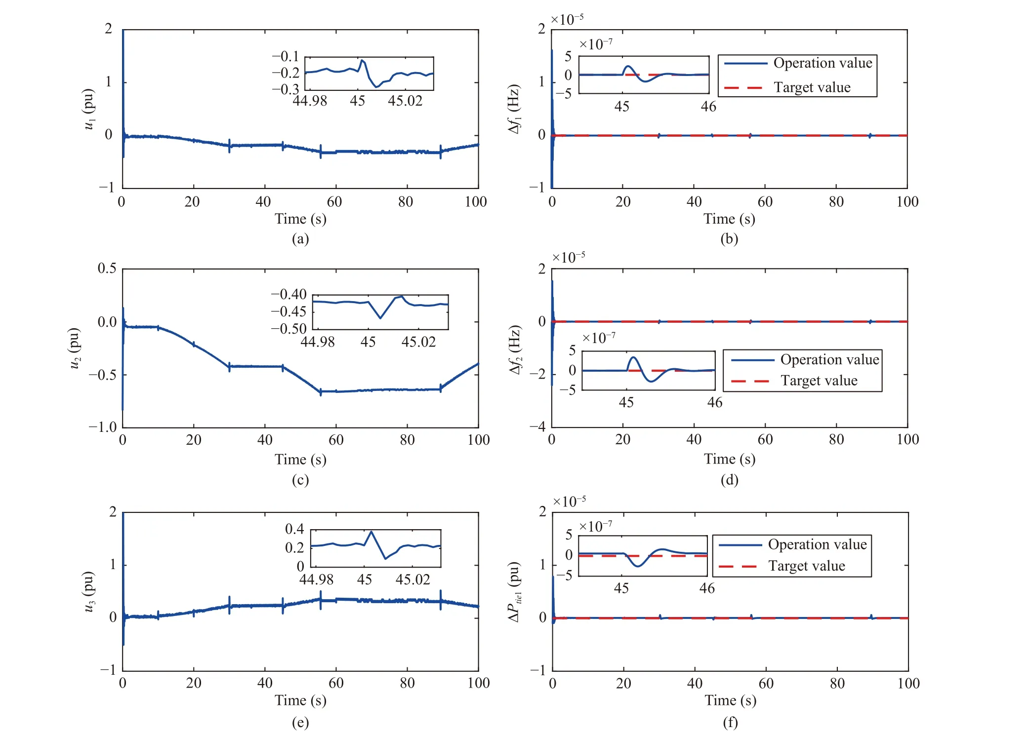
Fig. 8. Responses of the tow-area thermal power system (a) Control input u1; (b) Frequency deviation Δf1; (c) Control input u2; (d) Frequency deviation Δf2;(e) Control input u3; (f) Deviation of tie-line power flow ΔPtie1.

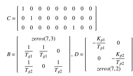
whereTch1= 0.3,Tch2= 0.17,Kp1= 1,Kp2= 0.67,Tp1= 10,Tp2= 8,Tg1= 0.1,Tg2= 0.4,R1=R2= 0.05,B1= 41,B2=81.5,KE1= 0.5,KE2= 0.5,T12= 3.77 (taken from [29]).
 IEEE/CAA Journal of Automatica Sinica2022年11期
- IEEE/CAA Journal of Automatica Sinica的其它文章
- A Bi-population Cooperative Optimization Algorithm Assisted by an Autoencoder for Medium-scale Expensive Problems
- Recursive Filtering for Nonlinear Systems With Self-Interferences Over Full-Duplex Relay Networks
- Receding-Horizon Trajectory Planning for Under-Actuated Autonomous Vehicles Based on Collaborative Neurodynamic Optimization
- A Zonotopic-Based Watermarking Design to Detect Replay Attacks
- On RNN-Based k-WTA Models With Time-Dependent Inputs
- Adaptive Generalized Eigenvector Estimating Algorithm for Hermitian Matrix Pencil
