A Novel Angle of Arrival Tracking Method in Large-Scale-Array Systems
Chen Zheng,Dekang Liu,Xuhui Ding,Xiangyuan Bu,Zhongshan Zhang
School of Information and Electronics,Beijing Institute of Technology,Beijing 100081,China
Abstract: In this paper, we investigate the problem of angle of arrival (AOA) tracking for the largescale array in terahertz (THz) communication, which has a large size and a narrow beam, highly demanding an accurate angle estimation.On the one hand,the system usually adopts a hybrid structure with limited radio-frequency (RF) chains, which increases the difficulty of angle estimation; on the other hand,the rapid mobility of users also brings new challenges to angle estimation.To address the above challenges, a two-stage tracking framework is proposed in this paper,which employs the random phase matrix and orthogonal long pilots in the first stage to reduce the complicated multi-user estimation to multiple single-user estimations, followed by using both wide and narrow beams in the second stage to serve high-speed and low-speed users.Furthermore,a generalized-approximated-message-passing (GAMP)method is proposed for facilitating a low-accuracy estimation of the angles, followed by adopting a modified expectation-maximization (EM) algorithm based phase estimation to unbiased estimate the instantaneous angle with the help of high-gain characteristics of the beams.The proposed structure can not only simplify the estimation complexity, but also improve the estimation accuracy due to its capability of transferring the non-linear problem of angle observation into a linear gaussian model.In addition,the Kalman tracking framework is employed for performing a continuous angle tracking.Numerical results show that the angle estimation based on the random phase matrix in the initial stage can obtain a high enough estimation accuracy,while the GAMP algorithm implemented in the second stage can quickly capture the angle range under the Rayleigh limit.The performance of the proposed EM-based tracking method is shown to outperform the traditional extended Kalman filter(EKF)method.
Keywords: angle tracking; hybrid MIMO communications;analog matrix
I.INTRODUCTION
To meet the growing demand for high data rate communication, Multi-Input Multi-Output (MIMO) technology has been widely regarded as one of the most important and fundamental technologies in future wireless communication networks [1-4].To obtain higher degrees of freedom, the scale of MIMO systems must be continuously increased.However, considering the massive MIMO technology,which usually uses hundreds or thousands of antenna elements, will be widely used in the fifth generation(5G)and beyond systems,the above extensive technology development route will soon encounter bottlenecks.Another key technology of the 5G system, namely the THz technology,has the characteristics of large bandwidth and short wavelength.Since this technology significantly reduces the physical size of the antenna compared with the microwave technology,it can bring new opportunities for the further development and wide application of MIMO technology.In theory, the maximum number of antenna elements supported by THz technology is dozens of times that of traditional microwave arrays.In particular, due to the benefits such as high band,weak signal scattering, and angular sparseness, THz technology is capable of supporting multiple spatially separate users at the same time,making it suitable for combining with massive MIMO systems.
Nevertheless,THz technology still faces many challenges.For example, limited by the art of state, the power of the THz amplifier is relatively small,and the THz signal is easily attenuated rapidly during transmission.To combat the above issue, channel estimation with a high accuracy is highly demanded [5-7],because even a small angular change may induce a serious performance degradation [8, 9].In traditional channel estimation and tracking methods,it highly relies on scanning technology to search the entire angle space, which becomes unsuitable for THz communication systems.In particular,in high-speed communication systems, frequent beam scanning is usually required to perform, causing a huge pilot overhead and thus reducing seriously the system’s resource utilization.To address this challenge, highperformance channel estimation for massive MIMO has been widely investigated[9,10].
Considering a large number of antennas will be comprised in a massive MIMO system, a full-digital structure may significantly increase both cost and design complexity of the system.To simplify the system design,a hybrid structure is usually employed,in which the number of radio-frequency(RF)chains can be reduced by using a team of shifters and combiners[11,12].Furthermore, an analog matrix based on a Discrete Fourier Transform(DFT)matrix is usually employed by the hybrid structure [13-16].It should be emphasized that reducing the number of RF chains does not always bring performance gains,because the reduction in the number of RF chains is accompanied by a reduction in the number of observations of the signal.In addition, because the beamwidth of a large-scale antenna system is extremely narrow, a large spatial range must be searched during the angle of arrival(AOA)estimation,which cannot be achieved with a limited RF chain.Even if we adopt some advanced technique(such as compressed sensing framework [17-19]), the simulation structure based on the DFT matrix can hardly bear the burden of the observation matrix.Therefore,it is necessary to investigate a new AOA tracking method for hybrid structures [20-22].
The large-scale antenna system will provide corresponding services for different types of users.Because these users have different location information,their requirements for angle tracking are also different[23,24].For instance, for pedestrian users, using a sharper and narrower beam can achieve good user tracking; in contrast, for high-speed moving targets such as passengers and drones, a wider beam is required to track and provide services for these highly dynamic users.In addition, considering the timevarying characteristics of user location and channel information, AOA estimation must be completed in a short time to obtain the ideal tracking effect [25-27].The continuous movement of the user inevitably leads to the continuous change of the beam angle.For example,for a user who is 2 meters away from the base station (BS) and moves at a speed of 1 m/s, its displacement within 1 second will cause a 30obeam angle change.For a system with a beamwidth of about 0.5o,the above angular change requires the BS to perform AOA estimation at least 60 or even 100 times per second to guarantee that user to be under tracking of the beam.
In essence, the AOA estimation has a typical nonlinear characteristic [28-31].According to the mathematical expression of the received signal, the AOA mainly affects the phase of the received signal,whereas the AOA itself is in a sine function in digital space frequency.Therefore, the large-scale array has serious nonlinear characteristics for the AOA estimation problem.To address this kind of non-linear problems, a locally linearized EKF or UKF model is usually employed in traditional AOA tracking techniques[19, 28, 31].For large-scale systems, on the other hand,new tracking methods are highly demanded due to the extremely sharp AOA and the risk of destroying locally linear approximations due to a mall angular change.
Aiming at the above problems, we investigate the channel tracking technology for large-scale antenna arrays in this paper.By sufficiently utilizing the sparse characteristics of the channel, we propose a compressed sensing method and a gradient descent method to achieve an accurate AOA estimation of each user in the initial phase.After that, a modified observation model with progressively reaching CRLB is proposed in the tracking phase by using both the GAMP method and the modified EM algorithm, which is capable of solving the problems of limited RF chains and non-linear AOA estimation.Furthermore,by using the proposed modified observation model,the mathematical form of the angle can be reconstructed and solved by using classical Kalman filtering.
The main contributions of this paper are reflected as follows:
· A two-stage angle tracking framework is proposed, in which the initial stage uses orthogonal long pilots to estimate the AOA through the compressed sensing framework.In the tracking stage,on the other hand,the observation model is modified and Kalman filtering can be employed for performing AOA estimation.
· Aiming at the problems such as limited RF chains,relatively few signal observations,and non-linear observations,etc,the special relationship between the AOA of the user in the beam and the signal phase is used for estimating the instantaneous AOA based on the method of signal’s phase estimation.
· To deal with the problem of severe mutual interference among multiple users that use short pilots,an EM-based iterative estimation method is proposed, which uses the condensing characteristics of the analog matrix beam to iteratively eliminate the interference of the other users.
The rest of the paper is organized as follows.Section II describes the system structure and gives out the received signal model.In Section III, we present the initial channel estimation method by using a random phase matrix.Furthermore, Section IV describes the angle tracking method.Section V evaluates the performance of the proposed algorithm through numerical simulations.Finally,conclusions are drawn in Section VI.
II.SYSTEM STRUCTURE AND SIGNAL MODEL
Consider a base-station (BS) equipped with a largescale array THz communication system that is capable of servingKusers simultaneously.To reduce the number of RF chains, a hybrid structure can be employed, as shown in Figure 1, in which the received signals atMantennas are combined intoNRF signals by using an analog matrix.Due to the users’mobility,the channel parameters of each user must be estimated and tracked by the BS for ensuring a reliable channel state information to be available at the BS during the communication process.
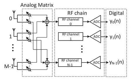
Figure 1.The BS equipped with a hybrid structure uses a large-scale half-wave array with M antennas to enable M received signals at these antennas to be combined into N signals by using a N×M analog matrix and to be processed by N RF chains.
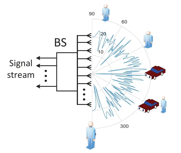
Figure 2.Random analog matrix based angle estimation in the initial stage.To avoid the disadvantage of using DFT beams, random analog matrix can be employed for constructing a CS structure.
2.1 Parameter Update Model
In the THz band, the signal transmission mainly depends on the line-of-sight (LOS) path, because both the reflection and scattering effects of the signal are extremely weak.Thanks to the short duration(i.e.,on the order of ms) of THz communication, the changes in the signal strength are so small as to be ignored.Therefore,the motion process of the parameters in the time-varying channel can be modeled as follows:

whereθ(n) corresponds to the angle of the channel at timen,w(n) represents the change of the angle caused by the user’s movement in two adjacent moments,u(n) denotes the error of the angle at timen.In practice,it is difficult for us to directly obtain the exact value ofw(n),that’s why we rewrite the model by takingw(n)as a state variable.To estimatew(n),we introduce another error termv(n), relying on which we can estimatew(n)by using a tracking method.

2.2 Initial Pilot Model
Consider a BS of a large-scale array system withMantennas, which can serveKsingle-antenna users simultaneously.The model of the received signal can be expressed:

whereGA ∈CN×Mrepresents the analog matrix,H=[h0,h1,··· ,hK-1]∈CM×Kdenotes the channel matrix ofKusers,hkstands for channel vector of userk, andP= [p0,p1,··· ,pK-1]∈CK×TLrepresents pilots ofKusers, each of which containsTLsymbols.Since the initial long pilots are orthogonal to each other,by using the matched filter,we get:

To reduce the complexity of the proposed system,a digital-analog hybrid structure is usually employed.In the proposed model,GAdenotes a flat analog matrix withN ≪M.Therefore, the dimension of the received signalrkis much smaller than that of the channelhk.As a result of rank deficit, the LMMSE estimation cannot be implemented.However, thanks to channel sparsity in angular domain,we can use the CS method to estimate the channelhk.First,consider the corresponding array manifold of the userk,as expressed:

whereθkdenotes the angle of userk.
The problem of initial channel parameter estimation can thus be written as follows:

Sincehkis a complex sinusoidal signal, parameter estimation can be performed by using spectrum estimation.However,the number of RF chains is far less than that of antennas, choosing the sub-matrix of the DFT as the analog matrixGAis evidently improper.Since oncehkfalls into the zero space of theGA, it will result inGAhk=0,implying that it is impossible to estimate the angle at all.
To address this issue, we can use beam scanning method by selecting the sub-matrix of the DFT matrix as theGAmatrix.However, due to the limited number of RF chains,multiple scans are still required.To reduce overhead,we propose a CS based estimation method,as shown in Figure 2.By using a random analog matrix, we can utilize the sparsity of angle space for estimating the channel with limited number of RF chains in one time.
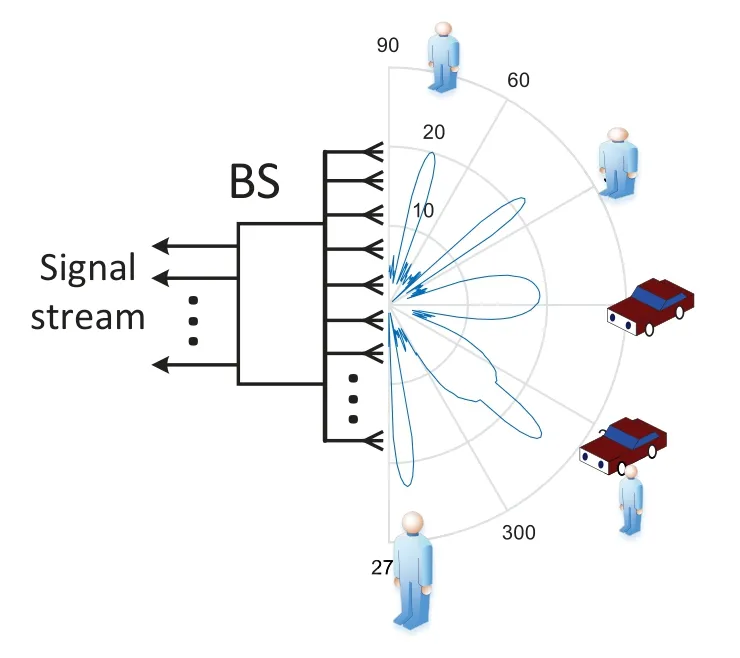
Figure 3.Beam based angle estimation in tracking stage.In communication stage, to acquire a high gain and enhance signal power, both DFT beam and Wide beam can be used to point to the users.The DFT beam can be used for slowly moving users,while for fast moving users,the Wide beam is used.
After the first-stage channel estimation,we can use the estimated parameters to construct both the analog matrixGAand the digital matrixGDthat will be used in the communication process.In particular,GAis used to both cover the users’ motion and offer high beam gain,whileGDis used to recover the signal accurately.
2.3 Tracking Pilot Model
In the tracking phase, short and nonorthogonal pilots are adopted.Short pilot symbols can bring many advantages.For example, by using tracking method,short pilots can ensure a high estimation accuracy.At the same time,using short pilot symbols can save more resources for data transmission.For short pilots, the signal model at timencan be expressed as follows:

whereq(n) = [q0(n),q1(n),··· ,qK-1(n)]T ∈CKrepresentsKuser’s pilot,and each of which contains one pilot symbol.The channel of userkcan still be expressed as:

The task of tracking is to estimateθk(n) based on the pilots as well as the past estimations in iterations 0~n-1.According to the current estimation, an updated digital matrixGD(n)is designed for communication.
In some cases, the user’s speed could be relatively slow (e.g., pedestrian), in which case we can use the DFT matrix to improve the beam gain.However, in some other cases, the users may move quickly (e.g.,high-speed train), in which case the users may deviate out of the DFT beam, since it is extremely narrow.Therefore, a wider beam must be employed, as shown in Figure 3.Furthermore, the analog matrixGAis not allowed to be changed frequently, but can only be designated at the initiating stage.Therefore,in the tracking process,only the digital matrixGD(n)can be adjusted.
Above all,the two-stage angle tracking time domain frame structure is shown in Figure 4.By adopting this timing model, we need to use a long pilot sequence once in the initial stage.In the tracking stage, the length of the pilot signal can be greatly reduced, thus more channel resources are allocated for communication data.

Figure 4.A time domain frame structure of the tracking system.
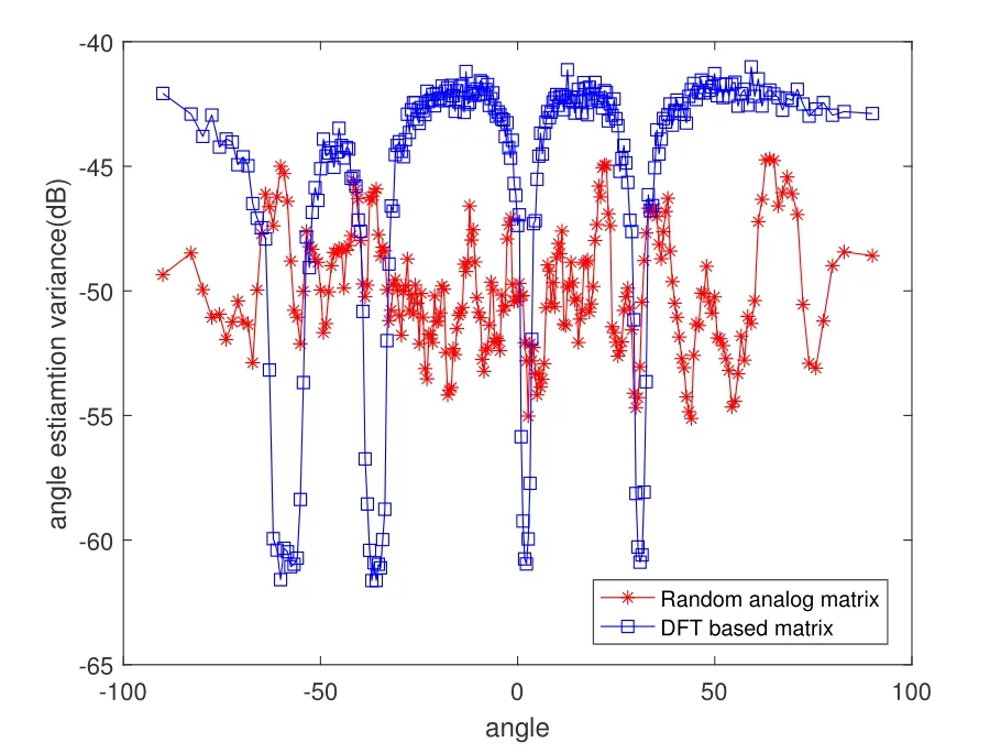
Figure 5.Initial phase, using random phase matrix to estimate the AOA.The random matrix has a smaller variance in angle estimation.
III.INITIAL CHANNEL ESTIMATION
In this section, we will introduce the proposed initial channel parameter estimation without prior knowledge through long pilots.Based on the results of channel parameter estimation,we can design an optimal analog matrix.
3.1 Random Matrix Based Angle Estimation
Since the BS has no prior information on the angles at the initializing stage, the DFT based beam is not suitable now.By using random analog matrix,a compressed sensing (CS) based channel method can be proposed.In this paper,we perform matched filtering to he received signal first.Relying on the matched filter, the interference between users can be eliminated while the power of the received signal can be enhanced.Consequently,the estimation accuracy can be substantially improved.For the channel parameterθk,the signal model can be further expressed as:

The entire angular space is discretized into several non-overlapping grids,where the signal only exists on the grid corresponding to the real angle.Therefore,the CS problem can be formulated.The long and orthogonal pilots lead to the fact that only one user is required to be estimated at one time,thus simplifying the problem solution.Furthermore,the random phase matrixGAcan be employed,avoiding the risk of missing signals that happens in the DFT matrix.
Constrained by the grids, a residual angle will remain.Therefore,based on the grid estimation,we can further search forθnear the exact estimation resultθk′.Using the MLE algorithm,a more accurate estimation can be formulated as:

Next,let us make such a definition:

where

We can get:
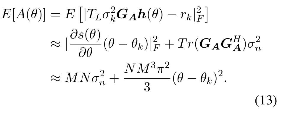
Evidently, forθ=θk,A(θ) =MNσ2nwhich is approximately 0 at high-SNR regime.While forθ /=θk,A(θ)grows rapidly.Since the pilots are long and orthogonal,the BS can achieve an estimation accuracy as high as CRLB,which can be taken as a benchmark.
3.2 Angular Range Analysis
To address the proposed CS problem,a random phases matrix is employed,in which the accuracy of the grid is limited by the array size.Therefore,the estimation error of the AOA can be denoted by 2π/M.According to the motion model of the signal,the AOA range before the next channel estimation can be given by

During the tracking procedure, the angular range can be expressed as:
· When Δθk ≥0, in the current communication process (i.e., at timen), the possible AOA range is[θk(n)-2π/M,θk(n)+2π/M+|Δθk|].
· When Δθk <0, in the current communication process (i.e., at timen), the possible AOA range is[θk(n)-2π/M -|Δθk|,θk(n)+2π/M].
For convenience, we will denote this range byBk(n),representing the angular range at timen.
3.3 Analog Matrix Design Based on Initial Estimation
Even after we completing the initial parameter estimation,the analog matrix based on the random phase distribution is still unsuitable for data transmission.Since such matrix has a very low beam gain, it cannot take advantage of the large-scale array.Therefore,the analog matrix needs to be redesigned.A simple method for redesigning this matrix is to assign a certain RF link directly to a user,followed by taking DFT matrix as beam.This method is capable of both maximizing the signal power and suppress interference.For userk,the responding beamformer can be expressed as:

Although the DFT beam can be employed for improving the signal’s SNR, it is sensitive to the user’s motion.To combat the user’s motion,a wider beam is highly required.Therefore, we formulate the following problem of wider beam design:

wherewkdenotes the coefficient of the radio frequency link corresponding to thek-th user.To satisfy the constraints of the analog matrix, the elements inwkhave a constant amplitude.For those wide beams pointing to different angles, we just make a rotation to the same wide beam with different angles.We first design a wide beam pointing at 0oas follows:

By performing a rotation

we can redirect this beam toθk.
For optimizing the above problem,we can approximate it as follows:

IV.ANGLE TRACKING
The large-scale channel tracking studied in this paper mainly comprises two issues:
· In practical scenarios,the angles may change fast.For high-speed moving users, the BS cannot directly use the narrow-beam DFT matrix, but can only seek a wider beam.For each user, only one RF chain can be assigned, making it hard to further improve the accuracy of angular estimation.
· The angle-observation model is a typical nonlinear model,to which the traditional Kalman filter cannot be directly used.In the proposed angle tracking technique, observations (includingφk=sinθkand)are highly non-linear,in which thesinθkcan be approximated by local linear expansion.However, even a small angular change may cause a significant changein the large-scale array systems.
Therefore, to address the above-mentioned first problem, we first use the GAMP method to perform gridded angular search [32, 33].After that, by using the modified EM algorithm, we can construct the linear observation of the signal[19,34]for improving the accuracy of estimation.
4.1 GAMP Based Angle Observation
First, we divide the entire space intoJnonoverlapping grids.According to the previous analysis,the user of interest should always be located inside the beam,thus reducing the search space.Considering that the THz beam is extremely narrow and the search duration is short,each user is allowed to occupy only one of theJdiscrete grids.When the system is servingUusers simultaneously, whether there exist users on one beam for each grid (e.g., beamθj) obeys the Bernoulli distribution.
According to the model of the received signal in the tracking phase,we can rewrite it as follows:
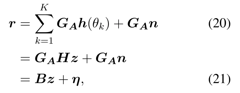
wherez ∈CJdenotes the signal vector, andH ∈CM×Jis the extended channel matrix.
Since there are onlyUusers, at mostUelements inzcan be 1, leaving all the other elements to be 0.In particular,z(i) = 1 means that a user exists at the angleθi,and the corresponding channel vector is theicolumn inH.In this way, we construct an extended observation model of the GAMP problem by defining the probability of user absence asλ.
Therefore,the distribution ofz(n)can be written asp(z(n)) =λnδ(z(n))+(1-λn)δ(z(n)-1),whereandBnrepresents the beam width atθn.We use the central limit theorem to approximate the Gaussian distributions of both the intermediate variableszandq.In this way, the conditional posterior distribution ofzandqcan be written as:

Due to the Gaussian approximation, we can easily calculate both the expectation and variance under the conditional posterior distribution ofzas:

Meanwhile, sincePQ|S(q|s;,μq) is a product of two Gaussian distribution,we can easily calculate both the expectation and variance ofqas:

Furthermore,we define new functions:
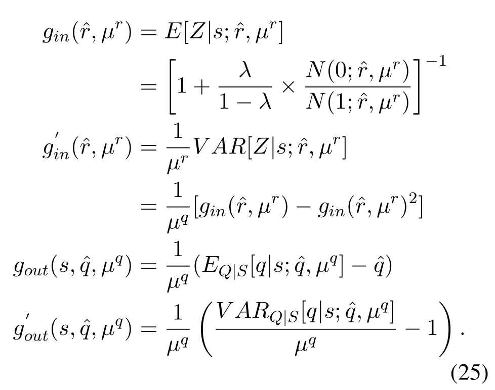
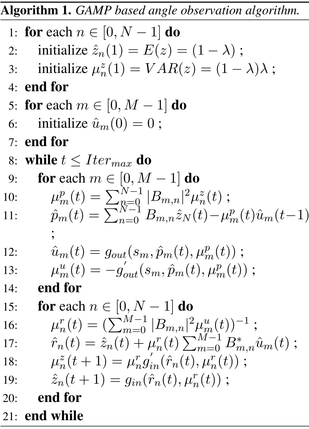
The algorithm can thus be described as Algorithm 1.
Forzthat needs to be estimated, the GAMP algorithm produces a list of estimateszn(t) and its corresponding varianceμzn(t).
4.2 EM Based Instantaneous Angle Observation
After performing GAMP method,we construct the linear gaussian observation model of angle.For largescale arrays, the SNR gain could be very high, making the MLE estimation ofφkbe progressive reaching CRLB.Thus,by using modified EM method,the estimation follows the Gaussian distribution can be given by:
Algorithm 1.GAMP based angle observation algorithm.1: for each n ∈[0,N -1]do 2: initialize ˆzn(1)=E(z)=(1-λ);3: initialize μzn(1)=V AR(z)=(1-λ)λ;4: end for 5: for each m ∈[0,M -1]do 6: initialize ˆum(0)=0;7: end for 8: while t ≤Itermax do 9: for each m ∈[0,M -1]do 10: μpm(t)=images/BZ_186_1615_916_1663_962.pngN-1n=0 |Bm,n|2μzn(t);11: ˆpm(t)=images/BZ_186_1610_974_1658_1020.pngN-1n=0 Bm,nˆzN(t)-μpm(t)ˆum(t-1);12: ˆum(t)=gout(sm,ˆpm(t),μpm(t));13: μum(t)=-g′out(sm,ˆpm(t),μpm(t));14: end for 15: for each n ∈[0,N -1]do 16: μrn(t)=(images/BZ_186_1623_1323_1671_1369.pngM-1m=0 |Bm,n|2μum(t))-1;17: ˆrn(t)= ˆzn(t)+μrn(t)images/BZ_186_1860_1381_1908_1427.pngM-1m=0 B*m,nˆum(t);18: μzn(t+1)=μrng′in(ˆrn(t),μrn(t));19: ˆzn(t+1)=gin(ˆrn(t),μrn(t));20: end for 21: end while

According toφk=sinθk,we get:

Therefore, we could construct a linear observation model for the formulated problem.Furthermore, by using the conditions of MLE and high SNR of largescale arrays, the signal observation model is guaranteed to have a Gaussian distribution.Intuitively speaking,φkcan be obtained by using grid-search method.However, in multi-user scenarios, employing the method of joint search would cause a dimensional disaster.In addition,in a high-SNR regime,the accuracy of the grid is at least one order of magnitude higher than that of CRLB,which induces a sharp increase in computational cost in order to approach CRLB.
In the following, we use the EM algorithm to construct a linear observation model for the angle in a high-SNR regime.
4.2.1 Likelihood Function Derivation
The received signal model in the tracking phase can be expressed as:

Since we can split the received signal into a superposition ofKuser signals, it can be further defined as:

wheresi(n) =GAhi(n)qiandηi(n) =GAwi(n),implying that at timen,thei-th user sends the pilotqithrough the corresponding channelhi(n), following which the responsexi(n)is generated.After that,we getFurthermore,we define:

The likelihood function can thus be written as:
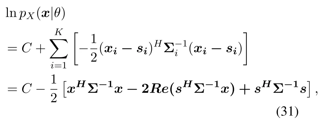
where Σirepresents the covariance matrix ofηi(n),Σ is a block diagonal matrix composed of Σi.For aK-user scenario, according to the previous noise decomposition, the corresponding noise power of each user is only 1/Kof the original noise power.According to the likelihood function,we can get the iterative form of the EM algorithm.
4.2.2 EM-Step
Following the likelihood function,we can get the conditional expectations:

Since we need to get the maximum value ofU(θ,θt), the items that are not related toθcan be omitted, implying that we need only to calculate the following item:
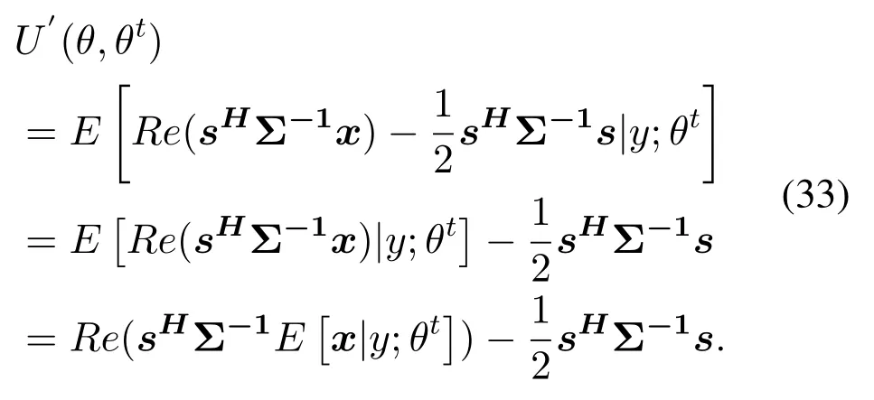
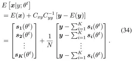
Thus,it is critical to computeE[x|y;θt]
After that, we could rewrite (33) into (35), as shown below.
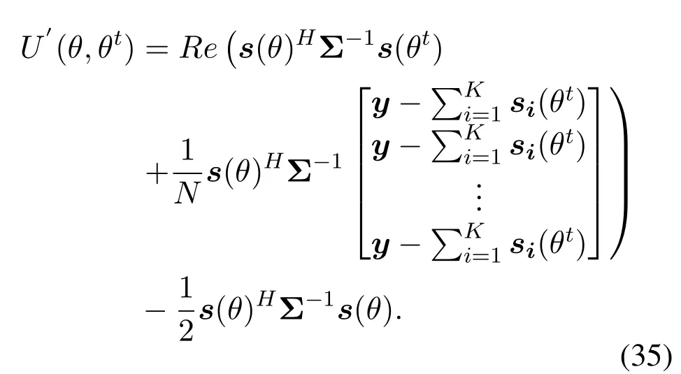
The maximization problem can be written as:

Looking closely at the above problems, it is shown that theθiof the AOA of thei-th user can be estimated separately, without the need to estimate theKangles of arrival simultaneously.In this case,the problem can be further reduced to

whereU′′(θ,θt) can be expressed as (38), as shown below.
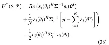
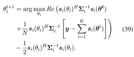
Furthermore, we can write the EM calculation as(39), as shown at the top of next page.Through the EM algorithm, we can mitigate the huge computational complexity of direct joint search.However,we note that this optimization problem is still not easy to solve.Therefore, we use the beam characteristics of large-scale hybrid arrays to further simplify this problem.
4.2.3 Simplified Large-Scale Array Problems
To simplify the solution of the maximization problem,we further examine the expression ofsi(θi)as:

For large-scale antenna systems,si(θi) itself exhibits the following characteristics due to the use of a hybrid structure.
· In order to increase the gain of the antenna array,the system uses both narrow and wide beams to serve slow and fast users, respectively.Theith element in the vectorsi(θi)represents thei-th user’s transmitted signal that passes through the corresponding beam combiner.Based on this,further utilizing both the beam’s high gain and low sidelobe characteristics can reduce the complexity of the estimation algorithm.
· According to(39), in each iteration, the received signalysubtracts the last expected received signal, following which it uses the remaining items for the current update.This inspires us that if the AOA of the otherK-1 users is known,the estimate of thei-th user can be obtained directly from the rest of the received signal

The more accurate the estimate of the AOA for otherK-1 users,the more accurate the AOA for usersi.By employing a large-scale array, both the beam gain SNR can be high,thus enabling an estimation with a high-enough accuracy.
· The hybrid structure has only one effective observation value for each user, in which the compressed sensing method is not applicable.However, it can be found that there is a correspondence between the arrival angle of the signal and the phase of the received signal,which can be estimated accordingly.Moreover,by taking the signal phase into account, we can avoid the deviation caused by the signal amplitude by eliminating thesi(θi)Hsi(θi) items.Therefore, the parameter-estimation problem based on the beam phase can be rewritten in the following form:

Therefore, by using the previous analysis, we can simplify the original optimization problem in the following manner.First, considering the fact that the received signal is the superposition of the signals ofKusers afterKbeam combiners, we can rewrite the form of the received signal as follows:
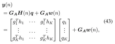
where the main diagonal element of theGAH(n)matrix implies that the user signal falls into its corresponding beam,in which case the signal amplitude is large.The off-diagonal elements of the matrix represent signals that other users fall into the current beam.Based on the above analysis,we can construct the following AOA search method:
· First, use the characteristics of narrow beams to make accurate AOA estimates for slow users served by narrow beams.Since the narrow beam gain is the highest,the attainable estimation accuracy is also the highest:~p1(θ1|y).
· Based on the estimation results of the narrow beam,the signal components of the slow users are eliminated from the signal.Therefore, we perform an accurate search for the users in a wide beam:
· Therefore, through the transmission of information between wide and narrow beams, we can get a preliminary estimate of the angle:
· After completing the preliminary estimation, we can perform an iterative estimation:~p(θ|,y).
In the following, we aim at estimation methods for both narrow-and wide-beam construction.
Narrow beam case
For the case of the DFT matrix, we can rewrite the received signal as:

It is shown the amplitude of the received signal decreases from the ideal valueMtoThere is an additional phase in the received signal,ejπ(M-1)Δφ,which is directly related to the angular offset.Since Δφis relatively small, this phase can be directly calculated.We can rewrite the signal observation model into the following form:

where
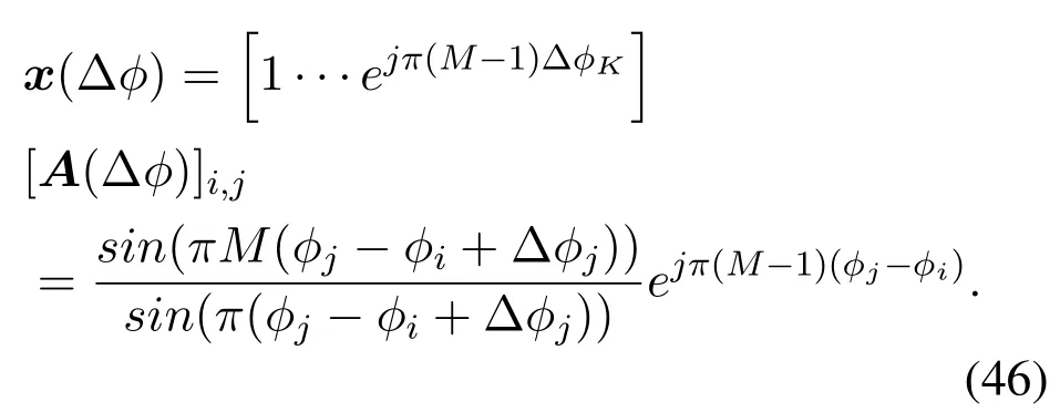
Obviously,sinceA(Δφ)is related to the amount to be estimated Δφ, we cannot getA(Δφ) in advance.However,A(Δφ)is approximately a diagonal matrix.
Wheni=j,we get

Wheni/=j,we get

In practice,the spatial angles between users are very different,i.e.,|φj-φi|>>1/Mwheni/=j,making[A(Δφ)]i,j ≈0.Since the DFT matrix is used, the signals outside are suppressed to be [A(Δφ)]i,j ≈0,while the signal inside is enhanced as[A(Δφ)]i,i >>1.Thus,we can estimate the angle based on the phase of the received signal.
Whent=0,the estimation of Δφis,leading to the following result:

Whent >0, based on the previous estimationwe have:

Wide beam case
However, for a wide beam system, we cannot directly obtain the analytical relationship between the phase of the received signal and the angle.Fortunately,with the help of GAMP method,the range of the user’s angle can be reduced to inside the Rayleigh limit of the array in the high-SNR regime.The signal phase changes slowly and continuously as the angle changes inside the beam.
When the signal ofk-th user falls into a certain beam,the noise as well as other users’signals are simplified ton.Furthermore, we can remove slow user’signal from the received signal by means discussed in narrow beam case.Because the large-scale array has a relatively high gain, the unknown interference and noisenis relatively small.We thus have:

We first estimate the phase of the received signal,followed by using the estimated phase to estimate the user’s angle.According to the previous analysis, for a wideband beam,the first-order approximation of the signal will result in a large error.Therefore, we estimate the AOA based on the signal phase.

The wide beam has a slowly changing phase response, and for a given estimation accuracy, only a few search iterations are required.In addition, similar to the DFT beam, we use Taylor-series expansion to the wide beam phase.Without loss of generality,we just analyze the results of thei-th RF chain.According to the previous derivation, by using the wide beamwwideto construct a beamwkpointing toθk,the signal received can be written as:

The first-order Taylor expansion of the signal phase can be expressed:

According to the phase differentiation,we get:
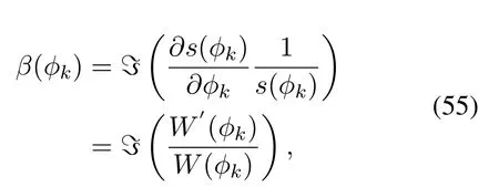
Whent=0,we get

Whent >0,we get

4.3 Angle Tracking by Kalman Method
According to the previous analysis, in the presence of high gain of the large-scale array, a high SNR can be assumed at that time.Under the condition of high SNR,the estimate ofθalso gradually obeys the Gaussian distribution.The observation model can thus be rewritten as:

wheren ~N(0,Σ),η ~N(0,Σ′), Σ represents the CRLB in high SNR,and Σ′denotes the CRLB after performingarcsin.We can thus rewrite the entire tracking model as follows:
State update model:

Algorithm 2.Tracking algorithm.Require: analog matrix GA;received signal y;Ensure: estimated angle ˆθ(n);digital matrix GD(n)1: Based on the CS structure,using a random analog matrix to estimate the AOA;2: Based on the CS estimated angle, using GD method to estimate the angle more accurately;3: for n=1,2,··· do 4: Using GAMP method to estimate the angle in n-th frame ˆφi(n),i=1,2,··· ,K;5: Initialize ˆφ(0)i (n) by (49), beam i is a narrow beam;6: Initialize ˆφ(0)i (n) by (56), beam i is a wide beam;7: while t ≤Itermax do 8: Based on (50) and (57), using modified EM method to calculate ˆφ(t)(n);9: end while 10: Based on estimated angles,Ψ(n)= ˆΦ(t)(n);11: Based on the system model and observation model, using Kalman filter to calculate parameters such as ˆθ(n|n) , ˆw(n|n) and GD(n) =images/BZ_191_332_1617_353_1663.png GAH(ˆθ(n|n))i-1.12: end for
Observation model:

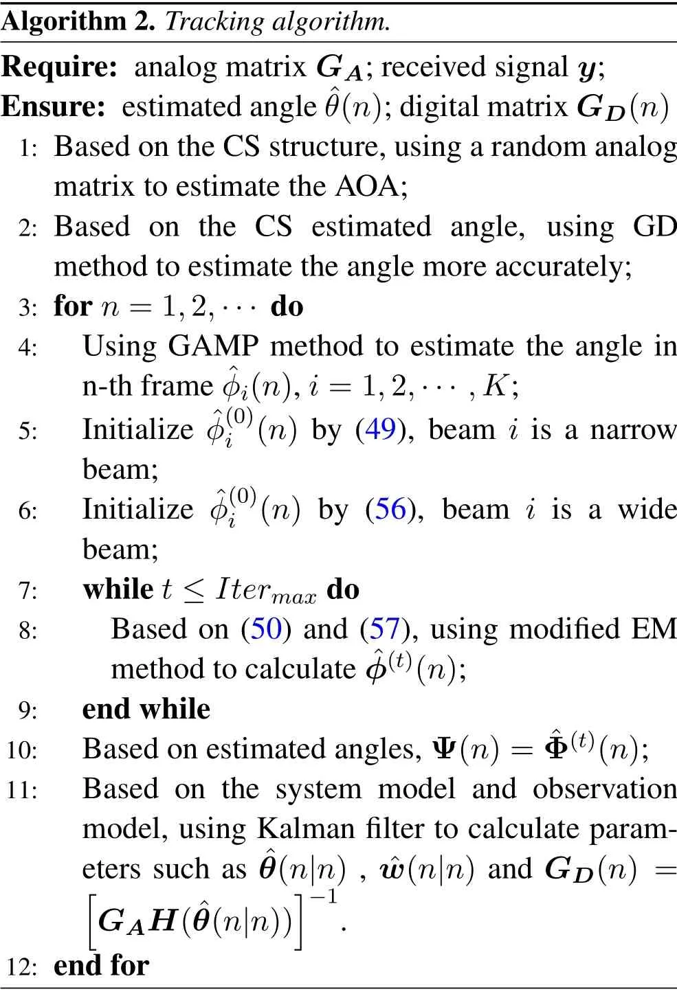
Therefore, for performing angle tracking in largescale antenna systems,we construct the system’s state update model and observation model through above methods.By using the modified observation model,we can construct the same structure as traditional Kalman filtering.The entire tracking algorithm can thus be described as Algorithm 2.
V.SIMULATION
In this section, the proposed algorithm is verified by numerical simulation.First,for the long pilot model in the initial stage,we verify the estimation performance based on the random phase matrix.Secondly, for the preliminary estimation of the AOA in the beam during the tracking process,we perform simulations to verify the estimated performance of the GAMP method.Finally,the performances of the modified EM algorithm and the EKF algorithm are compared in two aspects:instantaneous observation performance and tracking performance.Simulation results show that the observation performance and tracking performance of the proposed algorithm outperform the EKF algorithm in both motion models.
5.1 Sparse Channel Estimation in the Initial Stage
In the initial stage,we use an array ofM=64 antennas to estimate the AOA ofK= 6 users simultaneously.Because of the long pilots with orthogonality,at the receiving end,it is possible to both eliminate interference from other users through matching filtering operations and improve the SNR.The joint estimation can be simplified toKindependent angle estimations.Figure 5 compares the performance of random matrix and DFT matrix in estimation.It is shown that the performance of random matrix is much better in most angles, except in those angles which the DFT beam points to.Thanks to the Gaussian noise,the MLE estimation here can reach CRLB gradually.For higher SNR, the noise power becomes smaller and the peak value becomes higher.
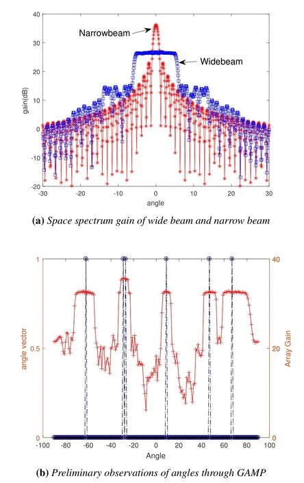
Figure 6.(a)The wide beam has a wider beamwidth at the cost of a lower power gain.(b)In tracking process,to deal with the problem that more than one angle have the same gain and phase in wide beam, preliminary observations of angles is performed through GAMP.
5.2 GAMP-Based Observations in the Tracking Phase
During the tracking phase, we assign one RF link to each user.For slower users,a beam based on the DFT matrix is allocated, and for faster users, a wide beam is allocated.From Figure 6(a), we can find that the beamwidth of the designed wide beam is much larger than that of the DFT.Meanwhile, to achieve a wider beam, we also have to sacrifice the beam gain, corresponding to about 10dB.In addition, the wide beam has higher side lobes and is more susceptible to interference from other users.In the tracking phase, because the beam is relatively wide, the angle can not be estimated just by indicating the center angle of the beam like that in the DFT narrow beam.Therefore, we need to use the GAMP method for preliminary AOA estimation.As shown in Figure 6(a), the system with an array of 128 antennas serves 6 highspeed users.Two of these users are closer, making their corresponding beams be overlap.It can be found through simulation that the GAMP algorithm can estimate the range of the AOA of each user according to the Rayleigh limit of the array.The estimation accuracy is sufficient to ensure the subsequent observation performance of the system.
5.3 Angle Observation Based on Modified EM Algorithm
The simulation in this section verifies the performance of the modified observation model based on the proposed EM algorithm.Compared with the method of local linearization, we use the relationship between the angle and the phase of the received signal.In the simulation, the number of antennas isM= 64, 128,and 256, and the number of users isK= 6.Each user corresponds to a radio frequency link,and there is no overlap between beams.We performed simulation verification for narrow beam and wide beam respectively.
5.3.1 Narrow Beam
Figure 7(a) and Figure 7(b) show the comparison of the performance between the modified EM algorithm and the traditional extended Kalman model in the case of using a narrow beam to serve slow users.Limited by the accuracy of local linearization, as the SNR increases,the higher-order residuals of Taylor expansion become the main source of estimation errors, and the observation error in extended Kalman model tends to be fixed and no longer decreases.Especially when the angle is at the edge of the beam, the linearization error rises sharply.The modified observation model based on EM algorithm can avoid the situation successfully.Therefore,Figure 7(a)and Figure 7(b)show that the modified observation model based on the EM algorithm can make full use of the performance gain of high SNR,improving the observation accuracy,and increasing the channel capacity.
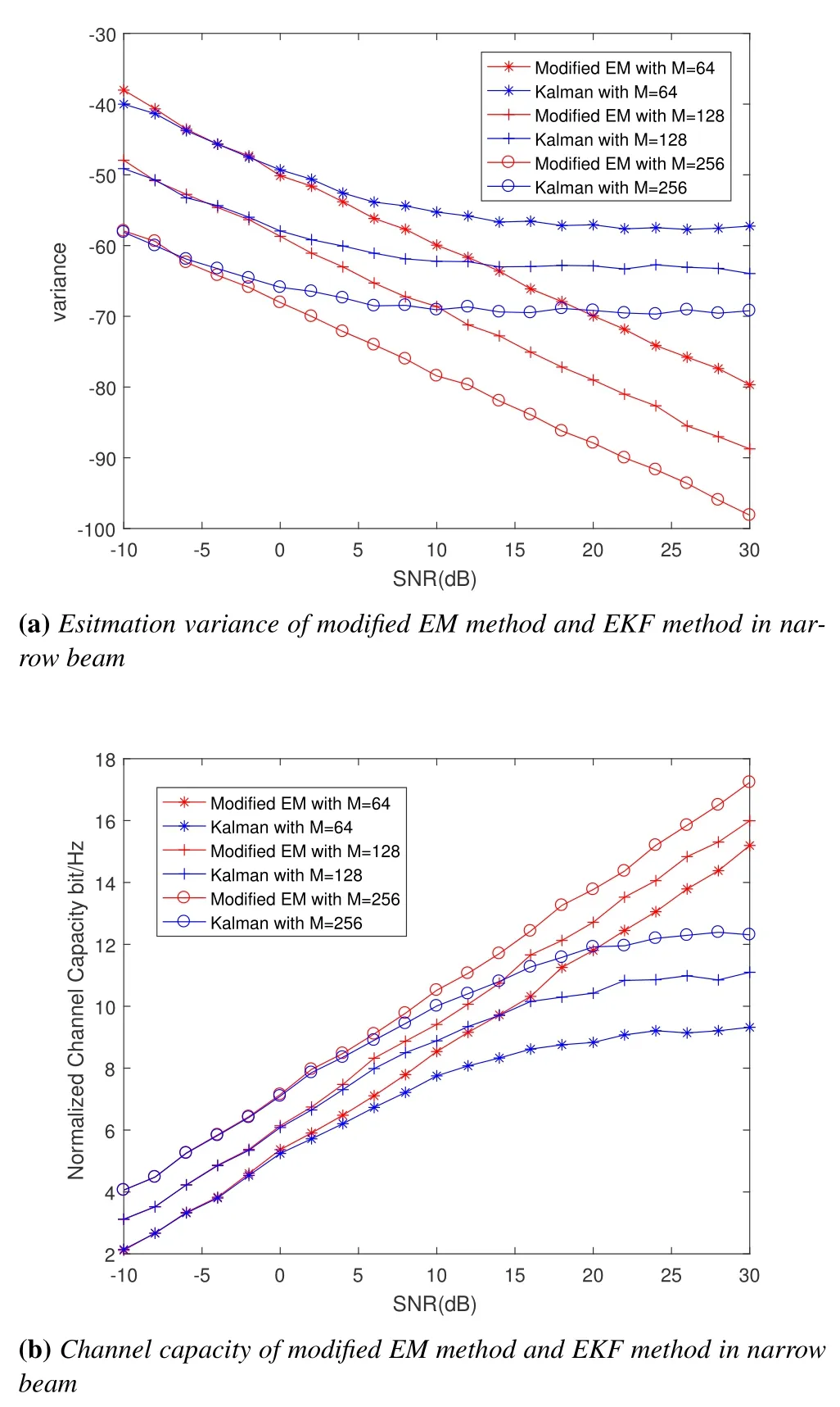
Figure 7.Angle observation based on modified EM method and EKF method with the DFT beam.(a) the estimation variance of only one observation; (b)the channel capacity based on angle observation.
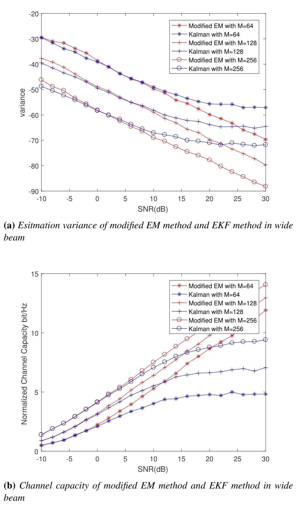
Figure 8.Angle observation based on modified EM method and EKF method with the wide beam.(a) the estimation variance of only one observation; (b)the channel capacity based on angle observation.
5.3.2 Wide Beam
Figure 8(a) and Figure 8(b) show the comparison of the observation performance between the modified observation model pair based on the EM algorithm and the traditional local linearization model in the case of using a wide beam to serve slow users.Similar to the previous results, the local linearization method under a wide beam is also limited by the Taylor series residual error.Compared with the narrow beam of the DFT matrix, under the wide beam, the estimation error is enhanced by about 10dB as a whole,which is consistent with the loss of the wide beam gain by 10dB relative to the narrow beam.Similarly,because the wide beam gain is low,the corresponding channel capacity is also reduced accordingly.
It is worth noting that the local linearization method has slightly better angular estimation error performance and channel capacity performance in the case of wide beams than in the case of narrow beams.This is because, for a narrow beam, when the AOA is located at the edge of the beam,it will not only cause a change in phase,but also a sharp attenuation of amplitude.Compared to the wide beam,it can be seen from the Figure 6(a) that inside the beam, the gain of the beam is fixed.Therefore,the gain of the wide beam is flatter and more suitable for local linearization operation.
The reason of the floor effect is that, for the AOA estimation, the linear approximation is a biased estimation, the estimation deviation corresponds to the higher-order term of Taylor expansion, and the phase estimation is unbiased.For the case where the noise power is large, since the noise is larger than the estimation deviation, the performance of this method is relatively close.When the noise power is small, the estimated deviation exceeds the noise,and the performance of the EKF is limited by the deviation and enters the step.
5.4 AOA Tracking Based on EM Algorithm
The tracking model proposed in this paper is compared with the traditional EKF model.The number of antennas is 128 and the number of users is 6.Two kinds of motion models are investigated, one is that the angle is moving along a sine trajectory,and the other is that the angle is moving along a straight trajectory.The simulation focuses on the performance of the system withSNR= 0dB, and the simulation is performed for narrow beam slow users and wide beam fast users respectively.
5.4.1 Narrow Beam
Aiming at the narrow beam situation, the simulation examined the case where the user has a sine motion model in the range of-37.7o ~-38.7oand the entire moving process lasted 500-time slots.Through the simulation result Figure 9(a)and Figure 9(b), we can find that both the tracking model provided in this paper and the traditional EKF model can track the angle.Through Figure 9(b), the algorithm provided in this paper has higher tracking accuracy.By observing Figure 9(a),as the user’s angle is at the edge of the beam,relative to the proposed algorithm, the tracking error of EKF increases significantly,and when the user’s angle is at the center of the beam.The performance of the two is basically the same.In Figure 9(a), at the positions of the sine peaks and troughs,the overall estimation result of EKF is relatively small.
Similar to the sine motion model,the simulation in Figure 10(a) and Figure 10(b) examine the situation where the user moves along a straight line in the range of-37.7o ~-38.7o, and the entire moving process lasts 500-time slots.Consistent with the results in Figure 9, the performance of the proposed algorithm is better than that of EKF at the edge of the beam.At the center of the beam,their performance are basically the same.From Figure 10(a) and Figure 10(b), compared with sine motion,the estimation accuracy of the algorithm is better.This is because the linear motion is more consist with the state update model.
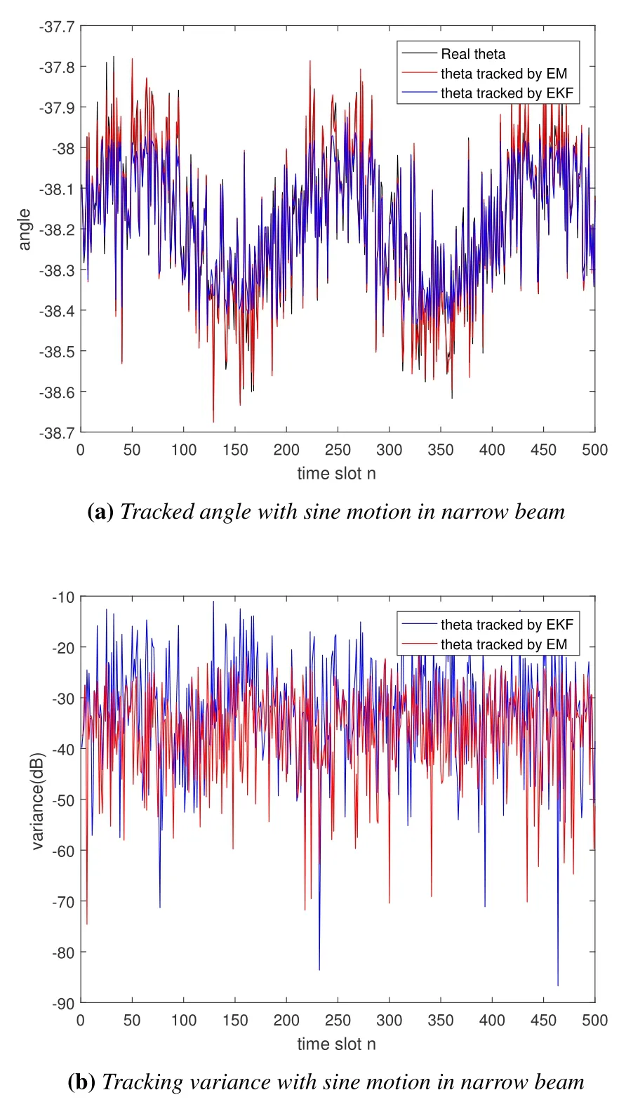
Figure 9.Tracking a sine-moving angle by modified EM method and EKF method with DFT beam.(a)angle tracked in time series;(b)variance tracked in time series.
5.4.2 Wide Beam
Figure 11(a) and Figure 11(b) show the situation where a user moves along a sine in a wide range of-34o ~-42ounder a wide beam.The entire movement process lasts 500-time slots.Similar to the narrow beam, in the case of a wide beam, the proposed algorithm still has higher tracking accuracy,and EKF also faces the problem of linear approximation error.However, compared with narrow beams, the performance of EKF is more stable under wide beams, and the performance of the two algorithms is much closer.Moreover, in Figure 11(b), the tracking error of the two algorithms is worse than that of the narrow beam due to the decrease of the beam gain.
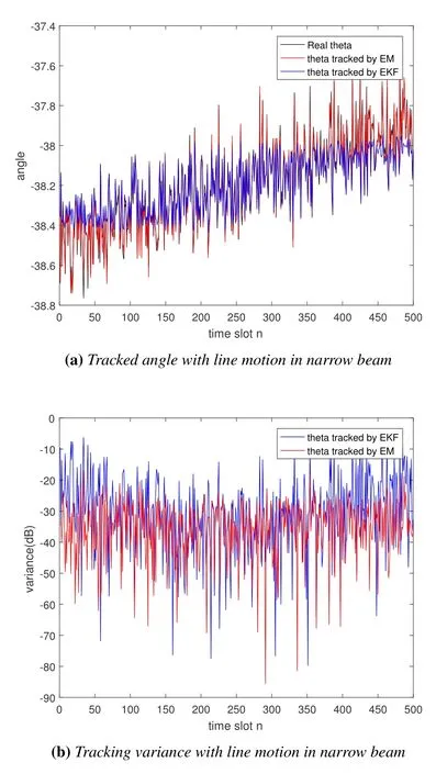
Figure 10.Tracking a line-moving angle by modified EM method and EKF method with DFT beam.(a)angle tracked in time series;(b)variance tracked in time series.
The simulation in Figure 12(a) and Figure 12(b)examine the situation where the user moves along a straight line in the range of-34o ~-42ounder a wide beam.As can be seen from Figure 12(a), both models can effectively track the AOA change.Compared with the narrow beam, in the wide beam, the performance of this algorithm is similar to that of the EKF,especially when the angle moves to the edge of the beam, the linear approximation in the EKF algorithm can still be close to the true angle.It can be found from Figure 12(b) that the performance of the algorithm in this paper is still better than the EKF algorithm.Similar to the narrow beam case,under wide beam, compared with the sinusoidal motion case, the algorithm has better estimation accuracy in the linear motion model.
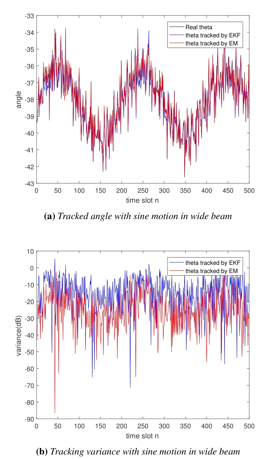
Figure 11.Tracking a sine-moving angle by modified EM method and EKF method with wide beam.(a)angle tracked in time series;(b)variance tracked in time series.
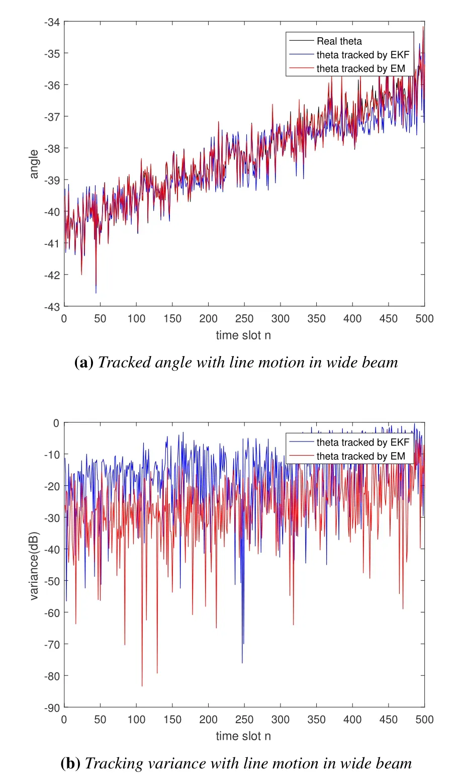
Figure 12.Tracking a line-moving angle by modified EM method and EKF method with wide beam.(a)angle tracked in time series;(b)variance tracked in time series.
VI.CONCLUSION
In this paper, we have investigated the angle tracking problem in a THz based large-scale antenna array using a hybrid structure.Aiming at the problem of dimensional disasters with a small number of RF chains, a few observations and a large angular search space,we have built an initial AOA estimation framework based on a random phase matrix.In the tracking phase, in view of the linearization-error problem in traditional EKF, a preliminary observation of GAMP method has been constructed, followed by a tracking framework proposed based on the modified EM algorithm.Furthermore, relying on phase estimation, accurate estimation can be achieved with lower computational complexity.Simulation results showed that the proposed outperform the traditional EKF algorithm in terms of both the estimation performance and tracking accuracy.
ACKNOWLEDGEMENT
This work is supported by the National Key Research and Development Program of China (No.SQ2019YFB180005).
- China Communications的其它文章
- GUEST EDITORIAL
- Reducing Cyclic Prefix Overhead Based on Symbol Repetition in NB-IoT-Based Maritime Communication
- Packet Transport for Maritime Communications:A Streaming Coded UDP Approach
- Trajectory Design for UAV-Enabled Maritime Secure Communications:A Reinforcement Learning Approach
- Hybrid Satellite-UAV-Terrestrial Maritime Networks:Network Selection for Users on A Vessel Optimized with Transmit Power and UAV Position
- Energy Harvesting Space-Air-Sea Integrated Networks for MEC-Enabled Maritime Internet of Things

