Reducing Cyclic Prefix Overhead Based on Symbol Repetition in NB-IoT-Based Maritime Communication
Tian Xiang,Daiming Qu,Faquan Zhang,Dejin Kong,*
1 School of Electronic and Electrical Engineering,Wuhan Textile University,Wuhan 430200,China
2 Sthe State Key Laboratory of New Textile Materials and Advanced Processing Technologies,Wuhan Textile University,Wuhan 430200,China
3 School of Electronic Information and Communication,Huazhong University of Science and Technology,Wuhan 430074,China
Abstract: With the increasing maritime activities, a great demand of wide-area maritime digital data services is needed.Therefore, Narrowband Internet of Things (NB-IoT) that can provide wide coverage has been expected as an application for maritime communication networks (MCNS).In this paper, we aim to enhance the spectral efficiency in NB-IoT by reducing the cyclic prefix(CP)overhead in random access signal without causing interference.The key point of the proposed scheme is the symbols transmitted for multiple times repeatedly in NB-IoT.Specifically,all CP are removed and multi-path fading effect is eliminated by using a repeated symbol to cover the disturbed symbol to construct a circular convolution structure of the channel with the same effect as adding CP.In addition,a single-tap equalization is still appropriate.To validate the effectiveness of the proposed scheme,simulation results are carried out with respect to the bit error ratio(BER).
Keywords:NB-IoT;narrowband physical random access channel;cyclic prefix;spectral efficiency
I.INTRODUCTION
Maritime activities and economy have increased rapidly in recent years,such as international shipping has accounted for 90 to 95 percent of world trade[1].Therefore,a high-speed and reliable maritime communications is in great demand in industries [2].Current transmissions in maritime communication networks(MCNs)can be divided into two types: marine satellites(e.g.,the Inmarsat)and on-shore base station(BSs)[3,4].The latter costs lower due to some existing mature technologies such as long-term evolution(LTE) and Narrowband Internet of Things (NB-IoT)[5].Specifically,NB-IoT has been considered suitable for maritime applications with high reliability requirements[6].
As a radio access technology, NB-IoT is proposed to provide the wide coverage for massive number of low-coast devices, enhance power saving, and reduce device complexity [7].In more details, NB-IoT offers a wider coverage (2.89 km) in urban areas than LoRa (2.68 km) [8], since different modulation techniques are used by two schemes.To reach the foregoing performance, orthogonal frequency division multiple (OFDM) with 180 kHZ system bandwidth has been oriented NB-IoT [9, 10], and repeat transmission mechanism has been adopted, i.e., symbols are transmitted repeatedly for multiple times to improve the signal-to-noise ratio(SNR)[11].
However, in classical repeating schemes, a longer than the initial uplink timing uncertainty cyclic prefix (CP) has to be inserted in front of each OFDM symbols,which reduces data transmission rate and the spectral efficiency [12, 13].Therefore, several different schemes have been proposed to reduce the CP overhead which can be divided into two categories,i.e.,schemes without distortion and schemes with distortion.In[14],a novel waveform with distortion was proposed with different symbols transmitted repeatedly at the same subcarrier and shared one CP to reduced overhead.In [15], to shorten CP, a root mean square delay spread optimization problem was built,and then a precoding scheme was acquired to maximize the sum rate subject.In [16], a power domain based scheme removes the inserting CP by adding a designed alignment signals of each transmitted OFDM symbol which is superimposed with the OFDM time domain signal to cancel intercarrier interference(ICI)and intersymbol interference(ISI).Nevertheless,there is no CP-free algorithm for narrowband physical random access channel (NPRACH) designed to request access to network.In more details, it transmits the first Single carrier frequency division multiple access(SC-FDMA) signal from user equipment to evolved node B in frequency hopping mode [17].Therefore,NPRACH also adopts CP in front of each symbol group(SG)to eliminate interference with spectrum efficiency lost[18,19].
In this paper, we aim to improve the spectral efficiency of waveform in NPRACH by reducing the CP overhead during the repetition procedures.Compared with the existing scheme in[16],the key point of the proposed scheme is that a single-tap equalization could be used for channel estimation since the repeating schemes construct the circular convolution structure of the transmitted signal and channel.In addition,no ISI and ICI are caused while the CP removed from each symbol.The proposed scheme in this paper aims to provides a new way to remove CP for future communication scenario similar to NPRACH.
The rest of the paper is organized as follow.Section II describes the classical system model of OFDM in NPRACH design.In Section III, a novel structure of signals is proposed,in which symbols are transmitted repeatedly with no CP.Simulation results are given in Section IV.Section V concludes this work.
II.CLASSICAL NPRACH SIGNAL WITH CP
In this section, we first retrospect the design of NPRACH in a general way.Then we use the mathematical expression to illustrate the design.
2.1 Random Access Preamble
A classical OFDM symbol in the NPRACH preamble consists of a CP portion and data symbols.We taking efficiency into consideration,with the length of CP grows,the spectral efficiency decreases.To reduce the CP overhead,a repetition scheme is adopted,whereasM-sample OFDM symbol transmitted repeatedly forRtimes, and then share a single CP.However, the value ofRcould not be asymptotically large in order to improve efficiency, keeping small enough to make the effect of channel variation negligible is essential.Therefore,five identical symbols with a CP are treated as an SG,and CP lengths can be either 266.7 μs or 66.7 μs according to the targeted cell size which is corresponding different SNR.
Since the phase difference of two adjacent received SGs may cause confusion in the time-of-arrival estimation, the single tone preamble is designed to hop across different subcarriers to avoid phase ambiguity[12].The random access preamble designed with frequency hopping(FH)is shown in Figure 1,which consists of four SGs and every SG uses one subcarrier which occupies one tone of 3.75-kHz in frequency domain for transmission.In the 3rd generation partnership project(3GPP)standard,four SGs are treated as a basic unit and the basic unit can be repeated 2j,j=0,1,··· ,7,times for coverage extension[19].
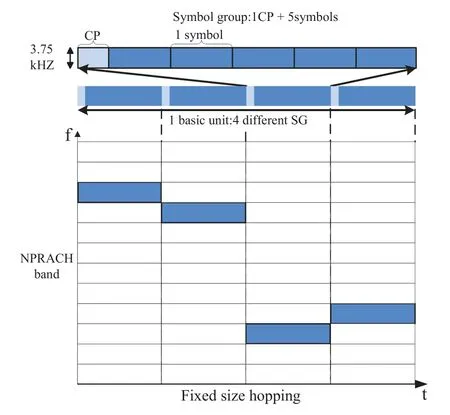
Figure 1.Illustration of a basic unit in the single tone NPRACH signal.

Figure 2.Classical OFDM model in NPRACH.
The hopping pattern of NPRACH consists of fixed within the basic unit and pseudo random hopping between the basic units.More specifically, inner layer hopping is applied within every 4 SGs, i.e., a singlesubcarrier hopping is used between the SGs{0,1}and SGs{2,3},while a six-subcarrier hopping is used between the SGs{1,2}.The hopping between the basic units is not fixed,a pseudo-random hopping pattern is defined in[19].
2.2 NPRACH Signal Model
In order to better present the rational of NPRACH transmission, we start with each SG which contains only one symbol and extend the results to general five symbol per SG later.In addition,to explain the difference between the classical scheme and the proposed scheme well,we focus on the process of one SG transmission.In Figure 2,the system flow chart consists of the discrete Fourier transform(DFT)and FH modules.At the transmitter, each SG occupies a fixed subcarrier and the equivalent baseband signal for NPRACH preamble before inserting CP is obtained as

wheresi[k] isk-th sample of the time domain waveform ofi-th SG,is the normalization constant,andxi,m0denotes the transmitted symbol onm0-th subcarrier during thei-th SG,m0∈[0,M -1].To maintain the orthogonality among subcarriers, and reject ISI,a sufficiently long CP is required as shown in Figure 3.Then the transmitted signal is defined as
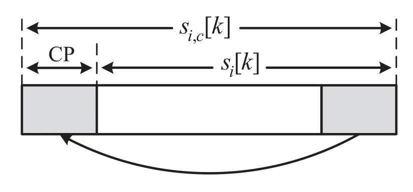
Figure 3.Inserting CP for an SG.
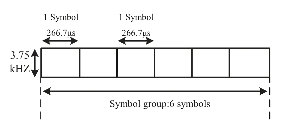
Figure 4.Structure of an SG in the proposed CP free scheme.

whereLis the length of CP.
Denote a multi-path channel impulse response ofLctaps note ash[l],l= 0,1,··· ,Lc -1.Then, the received equivalent baseband signal can be given as

where (*) stands for the linear convolution operation,andη[k]is the zero-mean complex additive white Gaussian noise(AWGN)with varianceσ2.
After the CP and tail removed, we obtained the received signal asri[k]and a DFT operation will be utilized.Note that, when each SG only consists of one symbol, the signal passes through anM-point DFT,and when each SG consists of five symbols, the receiver receives five symbols and performs fiveMpoint DFT operations.We assumeμpresents the index of received symbol ini-th SG, and the signal is obtained as

whereyi,μ[k] is the time domain waveform at thekth sample of theμ-th symbol in thei-th SG,Ngis size of an SG,denotes the channel frequency response of them0-th subcarrier, and noiseζm0,μis obtained by DFT operation of AWGN noise which satisfies the Gaussian distribution.
WhenHm0is available at the receivers, the simple single-tap equalization can be performed onyi,μ,and it is recovered as.Finally,we can obtain the symbols from the predefined frequency hopping mode as.
In order to evaluate the performance of classical scheme specifically, we consider an example of an SG message which is transmitted under Rayleigh fading channel, and the channel frequency response of them0-th subcarrier is assumed quasi-invariant during an SG.Naturally, assume the channel satisfiesThen,the averaged SNR of demodulated symbols at the receiver are written as
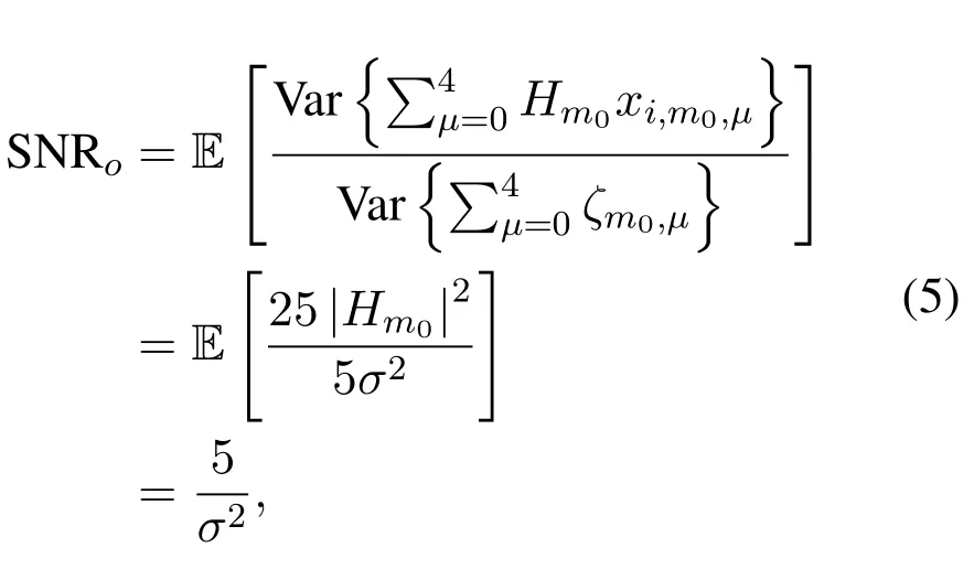
where Var{·}denotes the variance operation.
To enhance the achievable SNR at the receivers,repetition mechanism could be adopted, i.e., 4 SGs are treated as a basic unit and transmitted repeatedly multiple times to improve the quality of received signals.It is obvious that,with the increase of repetition number,the received SNR also increased.However,the insertion of CP for each SG consumes additional timefrequency resources, which reduces the spectral efficiency.
III.CP-FREE SCHEME
In this section, a CP free scheme is proposed by utilizing the symbol repetition as shown in Figure 4.In this figure, symbols at them0-th subcarrier transmitted repeatedly for 6 times, i.e., an SG consists of 6 identical symbol.Compared with the conventional scheme as shown in Figure 1,the CP is removed,leading to the enhanced spectral efficiency.In addition,two NPRACH formats are defined in the standard:format 0 with a CP duration of 66.7 μs , and format 1 with a CP duration of 266.7 μs [17].Note that, the time of added symbol is equal to the CP in format 1,which means the suggested method could be adapted directly without changing the frame structure.Without loss of generality and to explain the mathematical process better, we only present the first two symbols in an SG, since the operation of rest symbols are the same as the classical scheme.At the transmitter, assume the point size of DFT isM, and the equivalent baseband transmitted signal in NPRACH is obtained as
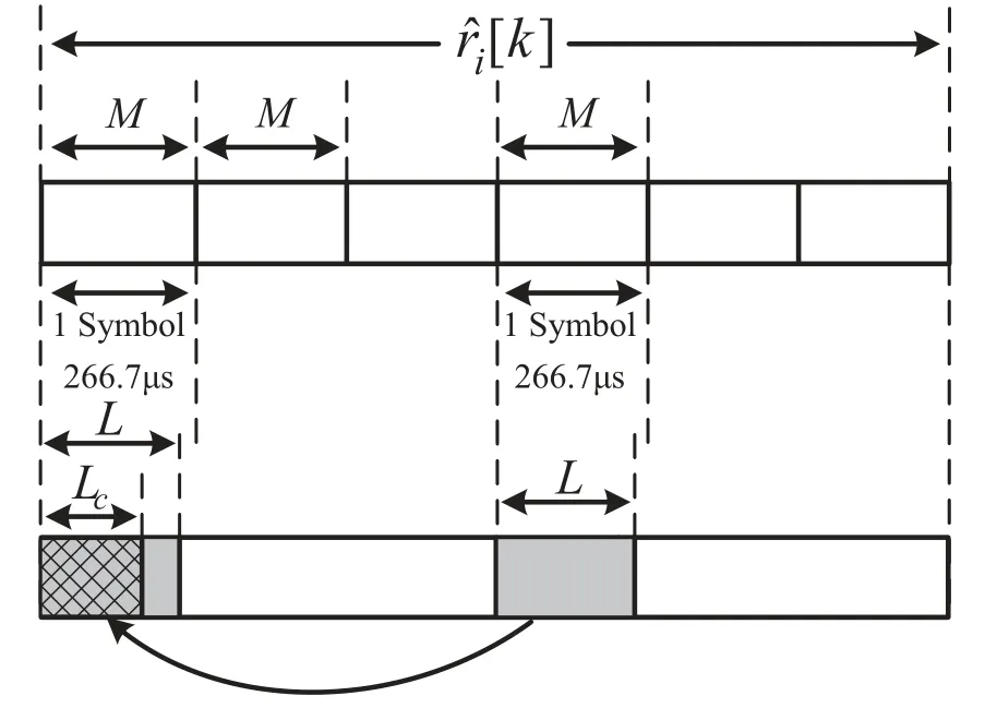
Figure 5.Illustration of the signal replacement.

Then repeated signal once at the same subcarrier,and the equivalent is rewritten as

The received signal without CP has gone through the multi-path fading channelh[l]and can be shown as

Removing the tail signal and substituting (7) into(8),then the received signal is obtained as

To erase the interference,part of the signal affected by multi-path effect is replaced by the beginning of the second half SG,as shown in Figure 5.It is noted that,regardless the number of symbols in an SG, only the previous series in the second half of SG is used to replace the disturbed part,since the second symbol may also be affected under ultra-high frequency selective channels.The signalri[k],k=Ng(i-1),··· ,Ng(i-1)+L-1, withLc ≤L ≤M, are replaced by the signals,and it is rewritten as

Figure 6.Illustration of the DFT operation at the received signal.
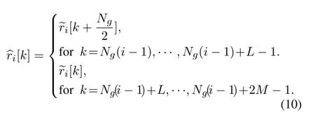
We constructed the circular convolution structure of the channel which has the same effect as adding CP by(10).And after a 2M-point DFT performed onri[k],we can formulate the received symbols as

whereHcmdenotes them-th subcarrier channel frequency response,Note that,a 2M-point DFT operation changed the subcarrier index of the received signal,i.e.,

As a remark, when the SG with two symbols, the receiver performs a 2M-point DFT on the signal,and when is six symbols, the receiver performs one 2Mpoint DFT operation and fourM-point DFT operations, i.e., 2M-point DFT is only performed on the first two symbols as shown in Figure 6.

Figure 7.Proposed CP-free scheme.
Since the noise power has a great influence on bit error rate (BER), the correlation processing for performing the noiseζmis addressed in detail.
In equation(9),channel noiseη[k]is Gaussian distributed vector with elements having zero mean andσ2variance.Additive noiseζmis obtained byη[k] after DFT operation, and it can be proven thatζmsatisfies the complex Gaussian distribution.To make the equation clear,we ignore the index of SG temporarily,and the noise equivalent is defined as

The mean ofζmis obtained as

where E{·}stands for the expectation operation.
It is shown in (10) that the front of the signal[k]is covered by the repeatedly transmitted signal.As a remark, even if the second symbol is not used as the replication reference, we could still regard it as directly covered from the second symbol, i.e.,[k] =[k+M],k=0,··· ,L-1.The reason goes that the channel is quasi-invariant during an SG and the noise is i.i.d..Then,variance ofζmcan be obtained as
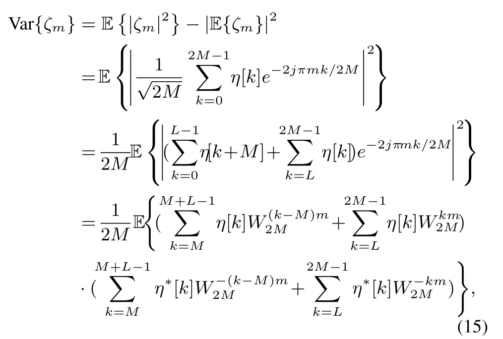
whereWMdenotese-j2π/M.
Since channel noiseη[k] follows Gaussian distribution, and we can obtained that E{η[k]η*[n]}= 0 whenk /=n.Therefore,(15)can be rewritten as

Based on the above steps, we could obtained that channel noise in the received signalζmsatisfies the complex Gaussian distribution with zero mean andvariance.Since the indexes of subcarriers are integers multiple of two, the variance of the channel noise could be simplified as
Recalling (11), the received signalcontains the transmitted symbol only atm-th(m= 2m0)subcarrier.Therefore,M-point downsampling is preformed on,and we can obtain that

Afterward, a single-tap equalization could be performed onφm0whenHcmis available at the receivers,and the transmitted symbols are recovered as

It should be noted that,Hcm=H2m0.Then we can obtain the signal after frequency dehopping model as ˆxi,and the system flow of the proposed scheme as shown in Figure 7.
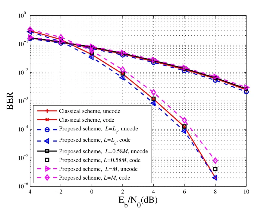
Figure 8.BER of the proposed CP-free scheme with different cover length.
Next, we aim to figure out the SNR of improved scheme through equation (16).Same as the previous section, the channel frequency response is assumed quasi-invariant during an SG, and it satisfiesWhen the number of symbols is 6 in an SG, after a linear combination performed, the signal can be obtained as
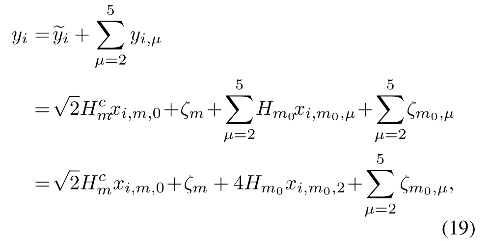
whereyiis a linear combination of six symbols inith SG,xi,m,0denotes ,xi,m,0denotes the symbol after 2M-point DFT andM-point downsampling, andxi,m0,μpresents theμ-th symbol ofi-th SG on them0-th subcarrier.
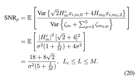
It is observed that SNR is decreased by the size of cover lengthL.Compared with the equation(5),whenL=M,the minimum value of SNRpis very close to SNRowhich is only a slightly higher about.WhenL≈0.863M,the value of SNRpand SNRoare equal.
In summary, the proposed CP-free scheme in NBIoT system promotes spectral efficiency.In addition,when the length ofLis less than 0.86M,the SNR of proposed scheme will be greater than the traditional one, and it may bring out a larger scale of coverage which makes it proper for marine communication with large-scale needs.However,the proposed scheme imposes a higher complexity than the conventional one due to the 2M-point IDFT at the transmitter.For equation (1) and (7), the complex-valued multiplication areMlogMandMlogMrespectively.Hence, the complex-valued multiplications of classical scheme is 6MlogM, while the novel scheme isMlogM+2Mlog 2M+ 4MlogM.Therefore, the total increased complexity is 2Mlog 2M -MlogM.Then,we can obtain the ratio of the increased complexity to the original complexity aswhich is acceptable.
IV.SIMULATION RESULTS
In this section, numerical simulations are carried out to evaluate the proposed CP-free scheme in terms of BER.The simulations are presented under multi-path channel models Stanford university interim-5(SUI-5)[20],and the channel profile is shown in Table 1.For a more comprehensive analysis,we simulate from two aspects.Firstly,the BERs of two schemes is compared with the same number of repetitions of SG.Furthermore, we also compare the BERs with the total number of symbols is the same in two arrangement.All the results are obtained by 10,000 simulation running withindependent channel.Detailed parameters for simulations are listed as follows.
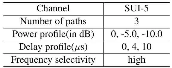
Table 1.Profile of SUI-5 channel model.
· Modulation: 4 Quadrature amplitude modulation
· code rate: 1/2(convolutional code)
· NPRACH band: 12 subcarriers
· CP length: 512 samples
· FFT size:M=512
· Conventional symbol group length: 512 + 5*512=3072 samples(1 CP and 5 symbols)
· Novel symbol group: 512*6 = 3072 samples(6 symbols)
Figure 8 compares the performances of BERs for the CP-free scheme and NPRACH arrangement under SUI-5 channel.The simulation results validate that with the increase ofL, the curve of BER also increases.It is obvious that, whenL=Lc, the proposed CP-free system is capable of outperforming the classical system by 0.31 dB, whenL= 0.58M, the proposed scheme achieves the same BER compare to the conventional one with CP, and whenL=M,the proposed CP-free scheme performs worse than the NPRACH scheme by 0.32 dB.Additionally,each simulation achieves almost the same coding gain.The reasons are summarized in the following.Due to the symbol replacement operation,a section of additive Gaussian noise becomes correlated from i.i.d.which results in the increasing noise power.Besides, the covered symbols also carry information, thus the replacement of these symbols decreases the total energy of an SG.The receiving SNR indicated that the theoretical value in Section III is reasonable.
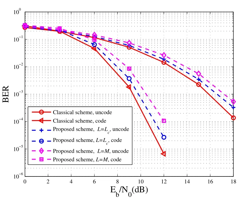
Figure 9.BER of the proposed CP-free scheme with same number symbols.
Figure 9 presents the BER performance for two schemes with the same number of symbols under SUI-5 channel, i.e., the total energy of two signals is the same.e.g.,if an SG repeats transmission for 20 times in proposed scheme, while the traditional scheme repeats transmission for 24 times.From the BER results, the curve of the CP-free scheme is higher than the NPRACH scheme,and the performance is reduced by up to 1.2 dB.The reason goes that BER improved in the Figure 8 due to the transmission of one more symbol than the classical scheme,even if the noise power in the CP-free scheme is lager than the tradition one.Therefore,the total number of symbols in two scheme is the same,then the proposed one will be worse.
In the following, we take an SG as an example to compare the spectral efficiency of the NPRACH and CP-free scheme.In NPRACH, an SG consists of 5 symbols with 1 CP,and the time duration of symbols and CP is 266.7μs.Therefore, the proposed scheme can improve the spectral efficiency by up to 20%.
V.CONCLUSION
In this paper, the CP elimination in NPRACH signal has been considered in depth.A new waveform was formulated to raise the spectral efficiency by up to 20%.The interference problems can be solved without changing the frame structure,so that it is compatibles to the NB-IoT protocol.Based on the replacement of interference symbol,we derived a circular convolution structure of the channel which brought the practicability of simple single-tap equalization at the receiver.Then,for each detected SG,we exploited two different point DFT to recover the signal and maximize its SNR.Simulation results are included to illustrate BER performance of the proposed algorithm,and it is capable of improving the attainable BER performance by 0.31 dB, which makes the novel method has the potential of dealing complicated maritime wireless propagation environment.
- China Communications的其它文章
- GUEST EDITORIAL
- Packet Transport for Maritime Communications:A Streaming Coded UDP Approach
- Trajectory Design for UAV-Enabled Maritime Secure Communications:A Reinforcement Learning Approach
- Hybrid Satellite-UAV-Terrestrial Maritime Networks:Network Selection for Users on A Vessel Optimized with Transmit Power and UAV Position
- Energy Harvesting Space-Air-Sea Integrated Networks for MEC-Enabled Maritime Internet of Things
- Networked TT&C for Mega Satellite Constellations:A Security Perspective

