Packet Transport for Maritime Communications:A Streaming Coded UDP Approach
Ye Li,Jianhao Yu,Liang Chen,Yingdong Hu,*,Xiaomin Chen,Jue Wang
1 School of Information Science and Technology,Nantong University,Nantong 226019,Jiangsu,China
2 Nantong Research Institute for Advanced Communication Technologies(NRIACT),Nantong 226019,Jiangsu,China
Abstract: The maritime communication network(MCN) plays an important role in the 6th generation(6G)system development.In MCNs,packet transport over long-distance lossy links will be ubiquitous.Transmission control protocol (TCP), the dominant transport protocol in the past decades, have had performance issues in such links.In this paper, we propose a novel transport approach which uses user datagram protocol (UDP) along with a simple yet effective bandwidth estimator for congestion control,and with a proactive packet-level forward erasure correction (FEC) code called streaming code to provide low-delay loss recovery without data retransmissions at all.We show that the approach can effectively address two issues of the state-of-the-art TCP variants in the long-distance lossy links, namely 1) the low bandwidth utilization caused by the slow increase of the congestion window (CWND) due to long roundtrip time (RTT) and the frequent CWND drop due to random and congestion losses, and 2) the high endto-end in-order delivery delay when re-transmissions are incurred to recover lost packets.In addition, we show that the scheme’s goodput has good smoothness and short-term intra-protocol fairness properties,which are beneficial for multimedia streaming and interactive applications that are prominent parts of today’s wireless traffic.
Keywords: maritime communication network;forward-erasure correction;congestion control
I.INTRODUCTION
The next-generation wireless networks are anticipated to be of a space-terrestrial-integrated scale[1],where maritime communication networks(MCNs)are indispensable for providing services for sailing, offshore wind power plants, and deep-sea drilling platforms etc [2].In MCNs, highly-mounted shore-based basestations,satellites and high altitude platforms(HAPs)are used[3].As a result,long-distance lossy wireless transmissions will be ubiquitous in MCNs.
Efficient packet transport over long-distance lossy links is crucial for MCN’s user experience.Most of the existing applications use the transmission control protocol(TCP)for reliable packet transport,where the congestion control algorithm(CCA)is the key for efficient and fair utilization of the link.Classical CCAs use two phases, namely theslow start(SS) and thecongestion avoidance(CA), to adjust the congestion window (CWND), which governs the number of inflight packets in the link.TCP faces challenges in MCNs.First,given a high round-trip time(RTT),the CWND may increase quite slowly in both SS and CA,leading to low link utilization for a long time.For example,a TCP download of a 30MB file can take about 20 seconds over a 100Mbps satellite link with 600ms RTT[4],showing that the connection is even far from ending SS.Second, random packet losses over the lossy link may cause CWND drops if the losses are perceived as congestion.This may significantly reduce the link utilization because CWND would then take many long RTTs to restore.
Over the years, many TCP variants have been proposed to address the above issues.To address the high RTT,TCP Hybla[5]adjusts CWND during SS and CA at a faster speed according to a much smaller reference RTT0instead of the actual RTT.However,no random loss is considered in the design.TCP Westwood [6]and Jersy[7]propose to set CWND based on the bandwidth estimation during CA, rather than recklessly halving it after detecting a packet loss.Alternatively,TCP Cubic[8]increases CWND according to a cubic function of the elapsed time since the last loss,i.e.,increases independently of the actual RTT,and therefore can quickly restore CWND.However, these schemes mostly focus on CA but no SS optimization is made for high RTT.Recently, Google proposes TCP BBR[9], which sets the CWND based on the estimated bandwidth-delay product (BDP) of the link, by alternately estimating the bottleneck bandwidth (BtlBw)and the round-trip propagation time(RTprop).In terrestrial networks,BBR has been shown to be capable of fully utilizing the available bandwidth while causing no queuing delay,even if there are random losses.However, in high RTT scenarios as in MCNs, BBR’s BtlBw estimation may take several long RTTs to converge, and a pacing gain of 2/ln 2 in its STARTUP phase may incur bursty losses and hence further postpone BtlBw’s stabilization.It has been shown that BBR’s throughput improvement over Cubic can vanish in satellite links[4],[10],[11].
Besides CCA, another critical components of TCP is the retransmission-based loss recovery procedure.In MCNs with long-distance links, the end-to-end inorder delivery delay can be another issue.The inorder delivery delay is defined as the time difference between a packet is first sent and that it is in-order delivered to the application layer at the receiver.The metric directly relates to the user experience and is of particular importance for multimedia streaming and interactive applications,which are increasingly popular in today’s Internet.When a packet is lost,it takes at least one RTT to be re-transmitted.During the retransmission,other received packets with sequence number larger than the lost packet have to wait in the buffer for in-order delivery.Such delay is in the order of RTT,and can be high in long-distance links and even higher if more than one retransmission is attempted.
In this paper,to jointly address the above issues for MCNs, we propose a new packet transport solution.The approach consists of two major ideas.First, we use a per-ACK based bandwidth estimator for congestion control, which helps quickly increase the sending rate at the beginning of the transmission.Second,on top of the CCA we completely rely on a lowdecoding-delay FEC code called streaming code[12],[13]to recover losses,where the repair packets are insertedproactivelybased on history ACKs.This helps maintain a low in-order delivery delay as compared to the conventional pure retransmission-based schemes or schemes using block FEC but relying on retransmissions for correcting residual losses.With the combined ideas, the CWND remains stable and packet losses are recovered with shorter delay, and therefore high and stable goodput can be achieved.Additionally, since no retransmission is required, the scheme can be implemented using the user datagram protocol(UDP), providing deployment flexibility.The paper makes two major contributions:
· A novel retransmission-free transport-layer solution is proposed for MCNs,which employs adaptive low-decoding-delay FEC on top of UDP with a CCA based on bandwidth estimation to provide congestion-aware sharing of the network.A detailed description of the architecture is provided.To the best of our knowledge,this is the first systematic work that considers adaptive streaming coding in a congestion-aware scenario.According to[14],the proposed FEC scheme may be categorized as FEC above congestion control.
· We conduct extensive evaluation of the scheme in ns-3 and compare it with the state-of-the-art schemes.We show that,over long distance lossy links,the scheme can achieve higher goodput and lower in-oder delivery delay.In addition, we show an interesting property of the scheme that it also has much smoother goodput than the existing schemes in most of the evaluated scenarios,corresponding to smaller goodput variation and better short-term fairness among the flows.
The paper is organized as follows.We first review the works related to this paper in II and highlight the differences.In III, the designed transport approach is presented.Performance evaluation of the proposed scheme is presented in IV.Several related problems are then discussed in V.The paper is concluded in VI.
II.RELATED WORKS
Improving TCP performance has been a fertile research area.Several TCP variants are relevant for the considered long-distance lossy links.Delay-based variants [15] where the increase of RTT is used as the congestion signal has been an important line of research other than the loss-based ones such as Cubic.However, it is recognized that pure delay-based variants would be suppressed when coexist with lossbased variants.Compound TCP [16] addresses this issue by effectively combining delay-based and lossbased approaches.More recently, PCC Vivace [17]is proposed with a much more complex and flexible utility function incorporating the sending rate, RTT evolution, and packet loss rates.Online convex optimization is adopted to adjust CWND based on the change of the utility.In[18], Copa is proposed to set CWND targeting a rate inversely proportional to the measured queueing delay,and is shown to be capable of quickly converging to a fair share of the bandwidth with a lower delay.Recently, reinforcement learning(RL) is introduced in [19] and [20], where adjusting CWND is modeled as a Markovian decision process.In[21]and[22],the initial CWND of SS,which is critical for achieving high throughput over links with high BDP,is optimized via deep RL.However,note that the cost of the RL-based schemes is the added complexity for tuning/training parameters.
Enhancing the loss recovery using packet-level FEC has attracted wide attention in the literature.In [23],XOR-based block FEC is adopted in TCP to reduce retransmissions.The retransmission process is only triggered if a block contains more than one loss.Note that a block decoding delay proportional to the block size can be incurred,which is a burden for large block size.Streaming coding(SC)reduces the block decoding delay by encoding from the source packets in an elastic sliding window.In [12] and [13], it is shown that inserting repair packets in the packet stream regularly or randomly can both achieve finite in-order decoding delay.However, [12] and [13] have only considered encoding at fixed rates.In [24], instead of intermittently sending repair packets, the random linear network coding(RLNC)packets are sent,and the encoding window can dynamically slide based on feedback.However, the scheme may still incur delivery delay due to the round-trip feedback for re-actively sliding the window.Unfortunately,the scheme has only been evaluated in scenarios with very short RTT(e.g.3ms).Note that[12], [13], [24]are more from coding theoretic perspective with discrete-time settings.No congestion control is considered, and therefore the interplay between the coding and the CCA is not explored.
Under the QUIC(Quick UDP Internet Connections)framework, [25] and [26] propose FEC schemes to insert repair packets among the normal QUIC packets.In [25], a fixed-rate block or convolutional FEC is used while[26]uses an XOR-based FEC across an adaptively sliding window.Both schemes can reduce the completion time in wireless lossy links when compared to the original QUIC with NewReno.However,both FECs in[25],[26]run below the CC.This means that CWND drop and retransmissions would still be incurred in case the FEC fails to recover a loss.
III.SC-UDP:SYSTEM DESIGN
We now describe the proposed scheme, referred to as the streaming coded UDP(SC-UDP).An overview of SC-UDP is shown in Figure 1.

Figure 1.Overview of SC-UDP system design.
3.1 Streaming Coded Transmissions
3.1.1 Encoding
At the sender, aSC-UDP queuestores data arriving from the application according to their arrival time.The data is represented assourcepackets, denoted as s0,s1,....Each packet contains the same number ofKbits, which, after appending necessary headers in layers below, can fit into the maximum transmission unit (MTU) of the underlying network.SuchKis referred to as the application data unit (ADU) size.When the CWND allows, a source orrepairpacket is sent via the UDP socket.Determine the CWND and the packet type to send are explained in Section 3.2.
Suppose that a source packet is to be sent and letiseqbe the recorded index (ID) of the previously sent source packet.siseq+1is then sent andiseqis incremented by 1.Alternatively, if a repair packet is to be sent, it is generated by encoding across the source packets in the SC-UDP queue thathave been previously sent in the source form.The encoding treats the information bits of each source packet as a vector of elements from a finite field F2mof size 2m, i.e., si’s are treated asK/melements from F2m.Letwsbe the ID of the oldest source packet in the queue, and denotewe≡iseq.The repair packet with a sequentially increasing repair IDkis written aswheregk,i’s are the encoding coefficients drawn from F2maccording to a pseudo-random number generator(PRNG).We refer to[ws,we]as theencoding window(EW) of the repair packet.The resulting packet is sent via UDP socket after appending a 4-field SC-UDP header shown in Figure 1,which is to enable decoding at the receiver.For a source packet,the source ID is indicated in the first field.Otherwise,the field is set null and the repair ID,ws,andweare delivered in the other 3 fields.Note that since the PRNG is used to draw the encoding coefficients of the repair packets,the coefficients need not to be carried by the header.Through the agreed PRNG seed, the receiver can retrieve the coefficients based on the repair ID.Note that, since each queued source packet will be sent in the source form exactly once,SC is a causal systematic code.
3.1.2 SC Decoding
Due to the lossy link and the unreliable nature of UDP,not all the packets may arrive at the receiver.SC-UDP relies on a decoding process to provide an in-order byte-stream interface to the application layer.
The receiver tracks the ID of the latest in-order delivered source packet, denoted asiord.Initially, the receiver is in thein-ordermode andiord=-1.This mode persists as long as the next received packet is siord+1,in which case the source packet is in-order delivered immediately,or a repair packet withwe≤iordwhich is redundant and is discarded.Otherwise,it indicates that some packets have lost and the receiver turns to theout-of-ordermode.An on-the-fly Gaussian elimination (OF-GE) decoder is thenactivatedto buffer the upcoming packets and attempt decoding.The packets are either out-of-order source packets with source ID>iord+1 or repair packets withwe > iord.The decoder forms a linear system of equations AS=C from the arriving packets with progressive row-operations, where the encoding coefficients of the packets form the rows of thedecoding matrixA and the(coded)information symbols of the packets form theinformation matrixC.With OF-GE,an upper-triangular A is always maintained.Denote≡iord+ 1, and letbe the largestweamong the EWs of the received repair packets.[,]is referred to as thedecoding window(DW).Note thatmay grow as packets accumulate.
An example decoding matrix formed over the time(from left to right)is shown in top-right corner of Figure 1.The decoder is activated since the source packet corresponding to the top row is lost(blank row in the left-most matrix).Four packets are buffered until the decoding can succeed in this example, where the 1’s correspond to two out-of-order source packets, and rows indicated by×and Δ correspond to the (rowoperation processed) encoding coefficients of two repair packets, respectively.Note that how the DW expands from 2 to 4 as packets accumulate.
The SC decoder succeeds when all the diagonals of the A becomes nonzero (i.e., full-rank).Backward row-operations are then performed on AS=C to complete recovering the source packets in the DW and deliver them altogether to the application.The inorder mode resumes with the newiord=.
3.1.3 ACK
Each received packet triggers an ACK packet for congestion and FEC control, which carries: 1) The type and ID of the latest received packet,referred to as theACKed packetof the ACK;2)The currentiord;3)The number of source packets received so far;4)The number of repair packets received so far.
At the sender,the ACKed source packet and the si’s in the SC-UDP queue withi ≤iordwill be flushed.The use of the rest of the feedback information will be explained in Section 3.2.Note that due to the propagation delay,the EW is usually wider than the DW,i.e.,ws≤andwe≥.This means that the sender may generate repair packets across packets that have been in-order delivered at the receiver but the ACKs have not arrive.Therefore, the receiver should store the delivered packets for a while,and only flush them after seeing repair packets with newerws.Such buffer requirement is proportional to the RTT.
3.2 Congestion and FEC Control
The congestion control determines whether a packet can be sent at a given time, which functions through setting the CWND that corresponds to how many packets can be in-flight in the network.In SC-UDP,an initial CWND is set to 10 packets,which follows standard practice.Thereafter,the update of the CWND is based on bandwidth and RTT estimations.
The FEC control determines whether a source or repair packet should be sent if sending is allowed by the CWND.The FEC control of SC-UDP is adaptive with the packet loss ratepeestimated based on history ACKs to proactively control the repair packet transmission.To achieve the above functions,the SCUDP sender records the time-stamps when sending each source and repair packet,and also records the total numbers of packets of the two types that have been transmitted up to each of the time-stamp.
3.2.1 Bandwidth and RTT Estimation
SC-UDP uses the time sliding window (TSW) estimator similar as that in TCP Jersy[7]to estimate the bandwidth.The estimation is per-ACK.Lettnbe the arriving time of then-th ACK,andXnbe the number of newly ACKed packets since the previous ACK.The estimation starts when the second ACK is received,and the first estimate is denoted asLater,the estimated bandwidth upon then-th ACK in the unit of packets is calculated as

where sRTT is the smoothed RTT by filtering the instantaneous RTT based on the ACK’s arriving time and the sending time of the ACKed packet, i.e.,iRTT =tacked-tsent.The smoothed RTT upon then-th ACK is sRTTn=α·sRTTn-1+(1-α)·iRTT,whereα=0.9 as in most CCAs.SC-UDP also tracks the minimum iRTT over the previous 10 seconds,denoted as RTTmin, which is to eliminate the effects of possible queueing delay and underlying path changes.
We note that there are other bandwidth estimators in the literature.The well-known packet-pair algorithm estimates the bandwidth asXn/(tn-tn-1),which is then low-pass filtered.In BBR, the delivery rate is sampled every RTT, and the maximum of the samples is used as the estimated bandwidth.Compared to them, SC-UDP chooses the TSW estimator partly because it quickly attains high bandwidth thanks to the per-ACK estimation,and partly because of its simplicity as it requires no extra filter parameters to tune.Based on our tests, TSW achieves higher throughput and better fairness in most of the evaluated scenarios.
SC-UDP’s CWND in the unit of packets is set to

Note that the initial estimation BW2can be large when the available bandwidth is high.An abrupt increase of CWND may cause buffer overflow losses.While such losses would not cause severe goodput drop as SC-UDP is insensitive to losses, a surge of queueing and decoding delay can be caused.To alleviate it,we pace at a rate ofγBWnwhen an abrupt CWND change is observed, whereγ >1 to not starve the following estimations.In the current SC-UDP,γ=2.
Given(1)and(2),we remark an important property that the estimated bandwidth can be strictly lower than the maximum available bandwidth and that the estimation oscillates over the time if the link is of light load.With a small initial CWND 10,note that there will be a gap between the ACK packet of the last sent packet of the initial window and that of the first packet of the next window, as illustrated in Figure 2.Since (1) is inversely proportional to the interval(tn-tn-1),BWnwill slightly drop when seeing a gap,and then restore upon the following ACKs, and so on.This gap could be completely closed only if packets are sent out at a rate larger than the estimated bandwidth until the link is fully occupied.Otherwise,the gap would always exist,and BWnand CWNDnwould experience oscillations.

Figure 2.Illustration of ACK gap.
The problem can be addressed by ignoring the gapped ACK,or using a CWND gain greater than one in(2).However,we note that this would significantly complicate the design because either correctly detecting the gap or properly choosing the CWND gain are challenging.The problem only exists when the link load is light and would disappear if multiple flows fill the link (i.e., multiplexing).Therefore, we choose to live with the gap.Interestingly, as will be shown in IV,such a“periodical”property turns to be beneficial in RTTmin estimation.
3.2.2PeEstimation and FEC Adaptation
Given an ACK packet arrived attn,letStnandRtnbe the numbers of the source and repair packets that are received by the receiver when receiving the ACKed packet,respectively.Suppose that the time of sending the ACKed packet isLetandRˆtnbe the numbers of transmitted source and repair packets up toThe instantaneous loss rate,which can be smoothed similar as sRTTnto.
LetStcandRtcbe the numbers of the source and repair packets sent up to the current timetc, respectively.We define a TimeToSendRepair() function which returns true if all the source packets in SC-UDP queue have been sent in the source form once, or ifwhereδ ∈(0,1).The rationale of the latter is that, if assuming randomly insert repair packets among the packets, the expected number of packets accumulated in the decoder,is known to be inversely proportional to the difference between the repair insert frequency and the loss rate [13].With the above setting, ifis constant, the decoding delay is approximately 1/δpackets.SC-UDP’s congestion and FEC control are summarized in Figure 3.
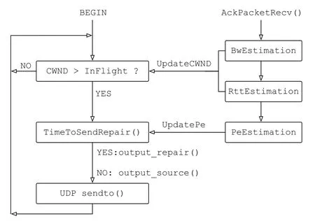
Figure 3.Flowchart of congestion and FEC control.
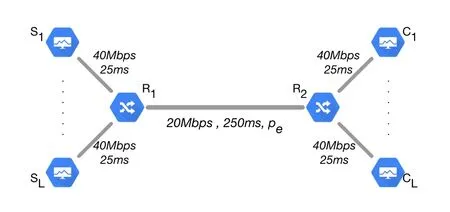
Figure 4.Network topology for performance evaluation.
IV.PERFORMANCE EVALUATION
We now evaluate the performance of SC-UDP by comparing with state-of-the-art schemes in ns-3.We pick Cubic,BBR,and Copa as the reference schemes,which are either widely adopted in production systems or being actively investigated in recent years.The source codes for the SC-UDP implementation,along with those for the reference schemes in this section, have been open-sourced at https://github.com/yeliqseu/sc-udp.
4.1 Experimental Setup
The schemes are evaluated in the dumbbell topology shown in Figure 4, whereLflows share a longdistance bottleneck link R1-R2.The bottleneck has 20Mbps bandwidth with propagation delayTbtl=250ms and a variable bidirectional random loss ratePeto be specified later.The bottleneck simulates an example GEO satellite link that may be leased by a MCN for cellular backhaul.Data flows are established from a left leaf Slto a corresponding right leaf Cl,l= 1,...,L.For simplicity, the leaf links set bandwidth 40Mbps and propagation delayTleaf= 25ms,with no random loss.The overall RTprop is 600ms.Queueing would occur at R1when the network becomes congested.
We implement the SC-UDP sender and receiver in two separate ns-3 applications using F28for encoding/decoding (the source codes will be opensourced after the paper is published), and are installed on Sl’s and Cl’s, respectively.We setδ= 0.02 in the current implementation of SCUDP.When evaluating TCP flows, the built-in ns-3 applications BulkSend and PacketSink are installed on Sl’s and Cl’s, respectively.We use the default Cubic from ns-3.33, and use BBR and Copa ported from Facebook’s QUIC implementation(https://github.com/facebookincubator/mvfst/; Theδof Copa is default to 0.05 for high throughput).
Throughout the evaluations, MTU of 1500 bytes is used, which is valid in most of existing systems.We set ADU size to 1440 bytes(i.e.,K= 11520)in SCUDP so that it fits in the MTU after taking the UDP and IP header sizes into account, where several bytes are reserved for extending SC-UDP’s header in the future.For TCP flows, we use the same 1440 bytes ADU for consistency and also set the maximum segment size (MSS) to 1440 bytes.The send and receive buffer size of TCP are set equally to 1000 MSSs,i.e., 11.52MB.This is close to the BDP of the link,which is 20Mbps×600ms = 12MB.Note that the buffers need to be large enough to hold the in-flight data, which is upper bounded by the CWND that is ideally equal to the BDP.The settings therefore ensure that the application would not be limited due to lack of buffer space.This is important for TCP variants such as BBR,where estimating the available bandwidth requires that sending is not application-limited.
As default in ns-3, the standard FqCoDel is installed as the traffic control discipline on all the network devices in the simulation.Evaluation in a FqCoDel-enabled environment is a reasonable choice as fq_codel has been Linux default for several years for controlling bufferbloat at the link layer.The default FqCoDel buffer size is 10240 packets, which is sufficient for the BDP of the simulated link.If not otherwise stated, all the other attributes in ns-3 simulations take the default values.Relevant attributes that may affect the absolute values of the results include the NetDevice’s transmission queue size, default to 100 packets.
4.2 Performance Metrics
We focus on the goodput, the in-order delivery delay,and the fairness and smoothness of the flows.The goodput is defined as the amount of data that has been delivered to the application divided by the elapsed time.Compared to the throughput, which is defined as the amount of received data divided by the time,the goodput measures the information rate seen by the application.In SC-UDP, the goodput by timetcan be expressed as goodput =(bps),whereiord+1 is the number of in-order delivered packets.
Lettsidenote the time each source packet siis sent from the sender for the first time.Lettdibe the time siis in-order delivered to the application at the receiver.Thein-order delivery delayof siis defined asDi=tdi - tsi.The delay of TCP consists of three components, i.e.,=niTp+Tqi+Tbi,whereTpis the propagation time,Tqiis the queueing time at intermediate nodes, andTbiis the waiting time in the receiver buffer.ni ≥1 is the transmitted times of the packet,ni >1 if it is re-transmitted.For SC-UDP, the delivery delay can be expressed as=Tp+Tqi+Tdi,whereTdiis the time the packet spent in the SC decoding process.
The Jain’s fair index is used to measure the fairness whenL >1 flows share the bottleneck.Let goodputlbe the goodput of flowl, the index is defined asWe are also interested in the dynamics of the flow s
moothness and the short-term fairness among the flows over the time.As multimedia streaming and interactive applications are taking more and more proportion of Internet traffic today,smooth goodput is increasingly vital for satisfactory quality of experience (QoE).A smooth goodput means that data is consistently delivered to the application rather than on an on-and-off pattern.We define a small period of time referred to as theobservation window(OW).The OW is usually of the length of several RTTs.We define the goodput within the OWs as the amount of data in-order delivered to the application within the OW divided by the length of the OW.The smoothness of flowlis characterized by thecoeffcient of variation(CoV) of its short-term goodputs, and is defined aswhere goodputl(t)’s are flowl’s short-term goodputs in the OWs and Et{·} is the average over the OWs.The short-term fairness among the flows can be characterized by measuring Jain’s fair index within the OWs [27], defined as SFI = Et{FI(t)}=
4.3 Simulation Results
We first present goodput comparisons of SC-UDP and the TCP variants in scenarios whereLflows of the same type share the bottleneck link.For each flow type, we simulateL= 1,2,5,10, respectively.Each flow sends up to 25000 ADUs, i.e., 36MB, which is large enough for simulating most of the online videos[28].For each simulatedL, the goodput of the flows is measured up to the time when the first out of theLflows completes the transmission.To understand how the long-distance and random loss affect the performance, the comparisons are first performed in reference scenarios with short-RTprop, i.e., in the same topology as Figure 4 but withTbtl=20ms andTleaf=5ms.This corresponds to 60ms RTprop.Using colored stacked bars, where one color represents a flow and the height represents the flow’s achieved goodput,the results in the short and long RTprop scenarios are presented in Figures 5(a)-(c) and Figures 5(d)-(e) forPe= 0%,0.1%,1%,respectively,which are the most commonly evaluated cases for GEO links, e.g.[18].ThePe’s stay constant throughout the transmission.However, we note that the scheme is adaptive to dynamicPe’s as described in 3.2.2.
We have the following major observations regarding goodput from Figure 5 to be detailed below.
· In scenarios without random losses,or in scenarios where the competition is quite high that the flows are bandwidth-limited,Cubic is efficient.
· In low-RTprop scenarios,BBR and Copa are efficient even ifPeis high.
· SC-UDP may achieve slightly lower goodput in low-RTProp or lossless scenarios,but is much advantageous in high-RTprop lossy scenarios.
Comparing Figures 5(a)-(c), we see that modern TCP variants such as BBR and Copa can achieve goodput close to the link capacity in short-RTprop scenarios, even with a high random packet loss rate 1%.As expected, Cubic is inefficient in the presence of random packet loss,where the link utilization for smallLis low due to CWND drop.For largerL=5,10 in Figure 5(b),Cubic’s sum goodput is close to the capacity.However, this is because the link becomes bandwidth-limited.The utilization decreases in the presence of more severe random loss (i.e., more frequent CWND drop),as shown in Figure 5(c).Figures 5(a)-(c) show that SC-UDP is insensitive to differentPe.SC-UDP achieves similar goodput as BBR and Copa forL >1,but the link utilization is lower forL=1.As mentioned,this is because SC-UDP’s bandwidth estimator does not reaches the maximum bandwidth when the link has very light load(e.g.,smallL).
Comparing Figs.5(d)-(f) with Figures 5(a)-(c) for eachPe,respectively,we see that the link utilization of all the schemes drops to some extent due to the long RTprop.For the long-RTprop scenario without random loss, Figure 5(d) shows that SC-UDP achieves higher goodput than Copa and Cubic forL= 1, and the goodput is similar for otherL’s.BBR’s behavior confirms the observations of[10]and[11]: the goodput is notably lower forL= 2,5,10 because severe congested dropping is incurred due to the high pacing gain of BBR flows at the same time.
In the presence of both long RTprop and random losses, SC-UDP’s goodput is the highest in Figures 5(e)-(f).The goodputs of SC-UDP withPe= 0.1%and 1%are almost the same,showing that it is insensitive to random packet losses in the scenarios.On the other hand, Copa and BBR become inefficient, a result of the slower CWND increase and/or the CWND drops due to retransmission timeout, as will be detailed later.
We now focus on RTprop = 600ms.In Figure 6,we calculate the CoVs of the flows for the short-term goodputs within OWs of length 5·RTprop = 3s.We pickL= 10 for illustration,and the observations are similar for otherL.Figure 6 shows that most of the SC-UDP flows have the least goodput variation.The fluctuation of the BBR flows is high in most of the cases.This is due to the unfairness of the flows and the periodic change of the pacing gain in BBR,which causes up-and-down in short-term goodputs.
In Figure 7, SFIs of theL= 10 flows up to the completion time of the first flow is plotted.Note that due to the different goodput and fairness performance,the completion times of the first flow is different for different flow types.Therefore, the curves are not of the same X-axis length.We see that SC-UDP has remarkably good SFI for all thePe’s.Along with Figure 6, this shows that the SC-UDP flows have quite stable and similar goodputs over the time.The fairness of SC-UDP is not surprising,because the sending rate is in accordance with the TSW bandwidth estimation,which has been shown to be fair in TCP Jersy[7].While Copa and Cubic’s SFIs fluctuate over the time,the fairness is mostly around 0.9.BBR’s SFIs are not satisfactory in these scenarios and also show a trend of decreasing over the time.Due to the unfairness,one BBR flow finishes the earliest among the schemes and hence results in the shortest SFI curve.In fact,from the stacks of Figure 5,we see that BBR in Figure 5(d)-(e)has several visibly shorter and longer stacks.
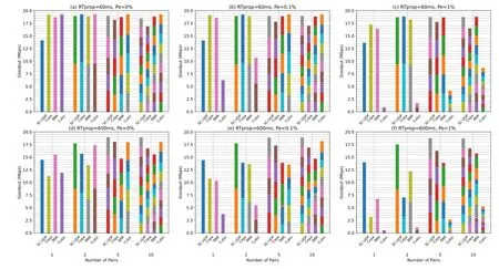
Figure 5.Goodput comparison of the schemes with low and high RTT.
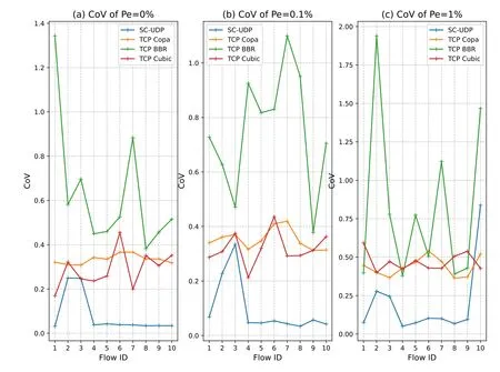
Figure 6.CoV of the L=10 flows for RTprop=600ms with OW of 5·RTprop.
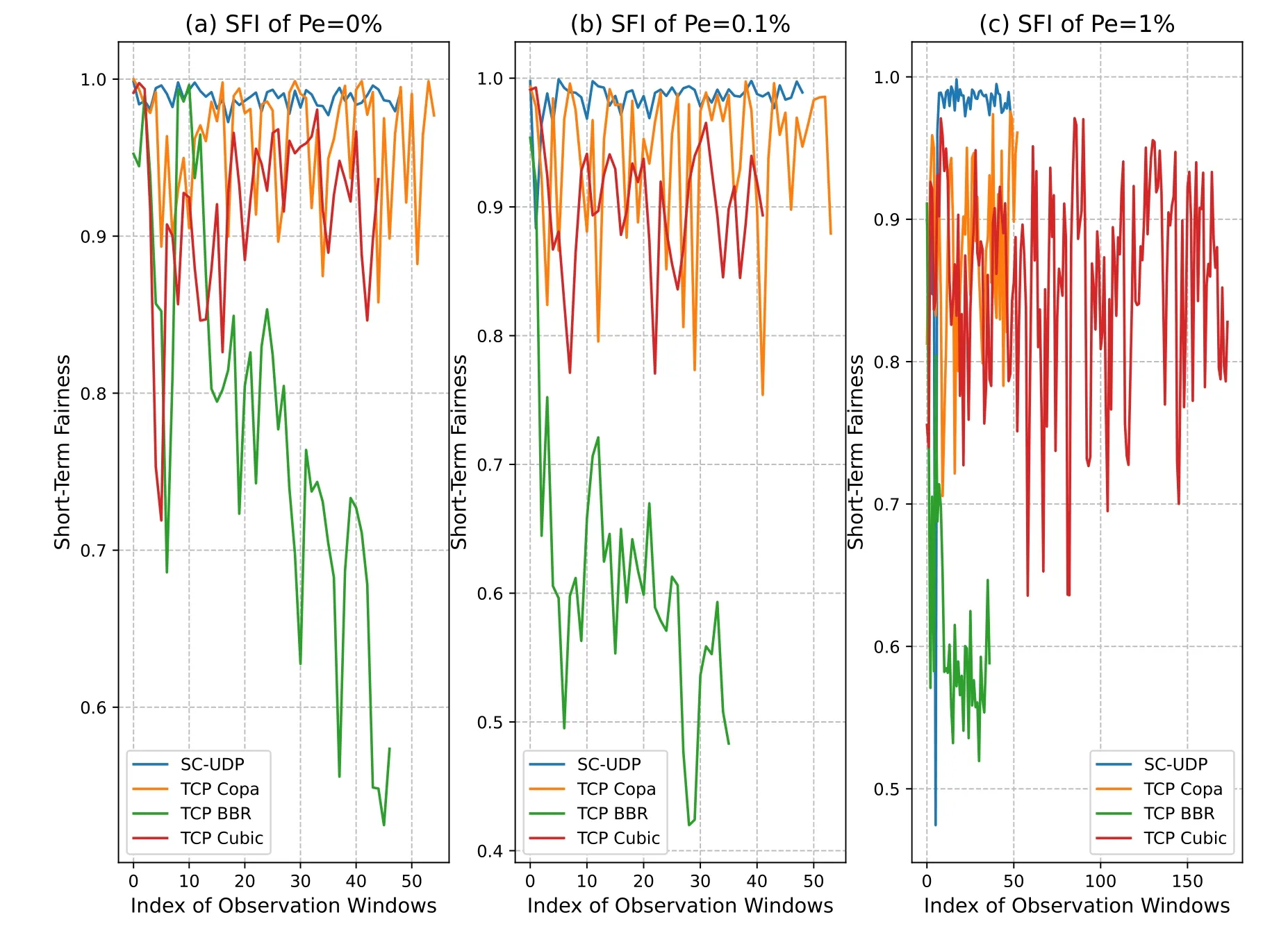
Figure 7.SFI of the L=10 flows for RTprop=600ms with OW of 5·RTprop.
In Figure 8 and Figure 9, we look into SC-UDP’s performance in more details, where we pickL= 1 andPe= 0.1%for presentation.In Figure 8, the cumulative goodput, the CWND over the time, and the in-order delivery delay of the packets are plotted for SC-UDP,Copa, BBR,and Cubic, respectively, where the cumulative goodput is defined as the amount of total delivered data divided by the current time.SCUDP completes the 36MB transmission before 25s,whereas Copa and BBR complete at about 30s, and we only show the curves in this time range.We see that the high goodput of SC-UDP comes from a quick CWND jump at the early time of the transmission, while the others experience a much slower increase.As mentioned in 3.2.1, SC-UDP’s CWND slightly oscillates around a stable value throughout the transmission (note that the BDP of the link is 20Mbps·0.6s/8/1440≈1000 packets).On the other hand,Copa’s CWND is also stable while BBR’s CWND experiences very dramatic changes over the time although there is only one flow in this scenario.Several sharp drops are due to RTT probe, where the CWND is reduced to 4.Cubic’s CWND, while has reached the BDP once,experiences several drops later due to the random losses.The delivery delay curves in Figure 8 show an outstanding advantage of SC-UDP,which is only slightly larger than the one-way propagation which is 300ms (an amplified curve is shown in Figure 9).While Cubic’s high delay is expected,the delay of Copa and BBR can also be more than 1 second for some packets when re-transmissions are incurred.
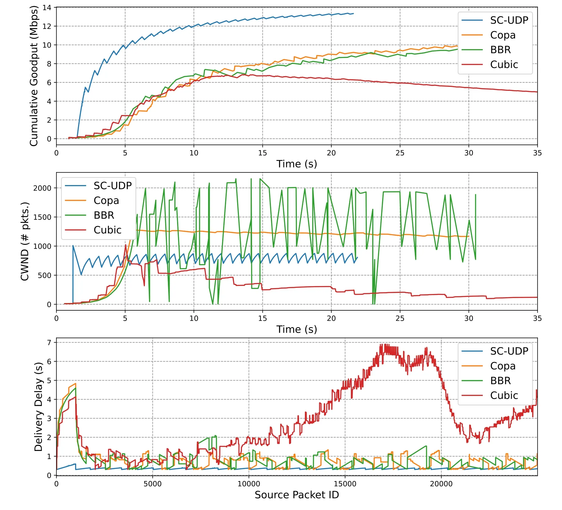
Figure 8.Comparison of goodput,CWND,and delivery delay for RTprop=600ms,L=1,Pe =0.1%.
Figure 9 shows the dynamics of SC-UDP over the time with more details, where the estimated bandwidth, iRTT,, the FEC code ratethe DW width, and the source packet in-order delivery time, are plotted respectively.We see that the estimated bandwidth only reaches the maximum1for the very first estimate (i.e., BW2), and then oscillates around 15Mbps, which has been explained in 3.2.1.The abrupt increase of the CWND after the first bandwidth estimation, even though the sending has been paced, causes a surge of iRTT,and the delivery time.However,this is only temporary.The iRTT then oscillates between 600ms and 700ms, and the oscillation is “synchronized” with the bandwidth estimation.We see that the drop of the bandwidth estimation has allowed the link to drain the queue, which provides an accurate estimation of the RTprop.The plottedhas accounted for both the congestion and random losses throughout the transmission, which is why>0.1%.The corresponding FEC rate is“synchronized” with.The rate drops at the end simply because all the source packets have been sent in the source form once and repair packets are sending out until the sender receives the stop packet.Throughout the transmission,SC decoder is activated once in a while to combat the losses,where for most of the time the DW width is below 40.
To see how higher packet loss rate affects the performance and how FEC improves the performance,we re-plot Figure 8 forPe= 1%in Figure 10,where we ignore Cubic as its performance is very bad(see Figure 5(f)).As a reference,we add a scheme where the dynamic XOR-based block FEC scheme of[23]is implemented within BBR,referred to as BBR-dFEC.Results of Copa-dFEC are similar, and therefore are not plotted to avoid overly complicated figures.
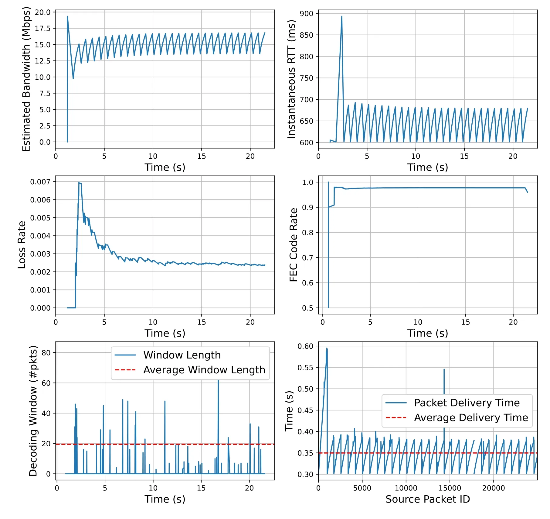
Figure 9.Dynamics of SC-UDP for RTprop=600ms,L=1,Pe =0.1%.
The reason of the reduced goodput of BBR and Copa withPe= 1%is now clear.For BBR,the maximum CWND drops to 1000 packets, indicating that the estimated bandwidth has dropped significantly as compared to Figure 8, which is due to higher packet loss rate.For Copa,we have observed several retransmission timeout events such that the CWND drops to 1, which prolong the completion significantly.Since more retransmissions are incurred for BBR and Copa,their delivery delay increases considerably as compared to Figure 8.The benefits of using FEC can be seen by comparing BBR with BBR-dFEC.By adding block-based FEC,some losses can be masked and retransmissions are avoided.Therefore, the goodput is improved thanks to the larger CWND (which is a result of higher estimated bandwidth), and lower delivery delay is achieved thanks to the avoided retransmissions.However,note that since BBR-dFEC would still incur retransmissions when there is residual loss, its performance is not as competitive as SC-UDP, which has the highest goodput and the lowest delivery delay.
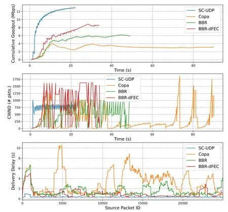
Figure 10.Comparison of goodput and delivery delay of the schemes for RTprop=600ms,L=1,Pe =1%.
V.DISCUSSION:GAINS AND COSTS
We first discuss the gains of SC-UDP to understand the fundamental reasons that it improves the performance.Generally,we may conclude that the gains come from two inter-played parts.The first part is contributed by the CCA based on the TSW bandwidth estimator,where a key is that the per-ACK bandwidth estimation quickly attains a high and stable value.Essentially,this can be thought of as skipping the SS phase.However, note that this gain would not be achieved alone without FEC:otherwise,a surge of losses and/or delay can be caused by the initial congestion.
The second part of the gains is from the proactive SC,which is two-fold.On the one hand,SC as a form of FEC,recovers the losses caused by random link errors or congestion, and therefore avoids unnecessary CWND drops.This is a part of gain that can also be achieved by using block FEC(e.g.[23]).On the other hand, and more importantly, SC avoids the delay that may be caused by retransmissions,which is in the order of RTT.While block FEC is also helpful here(see Figure 10),the delay cannot be completely eliminated using the block FEC because the residual losses have to be re-actively re-transmitted.Instead, SC proactively and continuously “prepays” repair packets according to the loss rate estimation based on history ACKs.A rough analysis comparing the two strategies can clearly reveal the difference.Consider a simple scenario with uniform random packet loss at rateϵ.Assume that a block XOR FEC adds a repair packet after everylsource packets.Note that if more than one loss occurs in a block, at least one RTT is needed for the retransmission such that the block can be in-order delivered to the application.Therefore, the expected delay that the packets wait in the receiver’s buffer is at leastDblock=[1-(1-ϵ)l-lϵ(1-ϵ)l-1]·RTT.Alternatively,assume that using SC which inserts a repair packet after everylsource packets.The expected number of packets in the SC decoder has been shown to be[12].Assume that the time interval that packets arrive at the receiver isTa.The expected delay to wait in the buffer is then·Ta.We can conclude that SC achieves lower delay if

for the givenϵandl.Note that RTT/Tais essentially the number of packets in flight in the link, implying that SC is beneficial for links with high BDP.The fundamental gain comes from thatSC waits for more repair packets at the delay cost in the order of Ta, instead of requesting retransmissions at the delay cost in the order of RTT.Here we see that the CCA enhancement is critical for realizing SC’s benefit too,as it determines the value ofTaand its dynamics.
SC-UDP indeed has some prices to pay.Besides the expected bandwidth cost of inserting repair packets which is a fraction of, a notable price is the computational cost for SC encoding and decoding,which is proportional to the EW and DW width.As a simplified analysis, assume that the packet loss rate isϵ.The expected DW width of randomly inserting repair packets with probabilityϵ+δis known to be[13], which is independent of the sending rate and RTT.In the current SC-UDP design,the encoding has included all the non-ACKed source packets, i.e., all the source packets that are in-flight.Denote the expected number of all the in-flight(source and repair) packets asN.The expected EW width is then E{We}=N·(1-ϵ-δ)≈Nfor smallϵandδ.
Another price of SC-UDP is the receiver buffer requirement.One part is for decoding, and is proportional to the DW width.Given that the DW width is usually not large, a careful implementation of OFGE is sufficient for maintaining low cost.The other part, as mentioned in 3.1.3, is that for storing the inorder delivered packets until the receiver seeing that the ACK packets have been received by the sender.
VI.CONCLUSION
In this paper, we have presented a streaming coded UDP approach for packet transport in NTNs, which often contain long-distance lossy links.The major conclusion from the work is that, retransmission-free reliable packet transport with high goodput, low delivery delay, and good fairness in the long-distance lossy links is feasible.The streaming coded transmissions with a bandwidth estimator for congestion control are the effective enablers.Moreover,the approach results in a much stable CWND throughout the transmissions and hence lead to much more stable goodput as well as better short-term fairness than the existing schemes,where CWND may change dramatically over the long-distance links.We believe that the proposed scheme can be a good solution for enhancing the transport-layer performance in the forthcoming spaceterrestrial-integrated networks.
ACKNOWLEDGMENT
This work is supported by Natural Science Foundation of China (NSFC) under Grant no.61801248,62171240, by the Key Research and Development Program of Jiangsu Province of China under Grant BE2021013-1, by Science and Technology Program of Nantong under JC2021121, by State Key Laboratory of Advanced Optical Communication Systems and Networks under Grant 2021GZKF006,and by the Postgraduate Research&Practice Innovation Program of Jiangsu Province KYCX223346.
The first author also would like to thank Songyang Zhang from Northeast University, China, for many helps in porting BBR and Copa to ns-3.
- China Communications的其它文章
- GUEST EDITORIAL
- Reducing Cyclic Prefix Overhead Based on Symbol Repetition in NB-IoT-Based Maritime Communication
- Trajectory Design for UAV-Enabled Maritime Secure Communications:A Reinforcement Learning Approach
- Hybrid Satellite-UAV-Terrestrial Maritime Networks:Network Selection for Users on A Vessel Optimized with Transmit Power and UAV Position
- Energy Harvesting Space-Air-Sea Integrated Networks for MEC-Enabled Maritime Internet of Things
- Networked TT&C for Mega Satellite Constellations:A Security Perspective

