Configurable Virtual MIMO via UAV Swarm:Channel Modeling and Spatial Correlation Analysis
Jiachen Qian,Jue Wang,Shi Jin,*
1 National Mobile Communications Research Laboratory,Southeast University,Nanjing 210096,China
2 School of Information Science and Technology,Nantong University,Nantong 226109,China
3 Nantong Research Institute for Advanced Communication Technologies,Nantong 226109,China
Abstract: Air-to-ground wireless channel modeling for unmanned aerial vehicle (UAV) communications has been widely studied.However,channel modeling for UAV swarm-enabled cooperative communication still needs investigation,where the impact of UAV positions on the spatial channel characteristics is of particular importance.In this paper, we consider a UAV swarm-enabled virtual multiple input multiple output(MIMO)system,where multiple single-antenna UAVs cooperatively transmit to multiple ground users(GUs).We establish a common coordinate system, as well as a UAV swarm-oriented coordinate system, to describe the relative positions of the GUs and the UAV elements, respectively.Based on the established coordinate systems,geometric ray superposition method is applied to describe the spatial channel matrix.The proposed modeling framework can be directly used to describe the line-of-sight and two-ray propagations,and can be extended for including more practical spatial features such as multipath scattering, inter-UAV blockage,and random UAV jittering,etc.Based on the proposed model,we further analyze the spatial correlation among the virtual MIMO links of GUs located at different positions.Via extensive simulations, we show that thanks to the flexible deployment of UAVs,the virtual MIMO array structure can be conveniently configured to get desired channel properties, such as the channel capacity,eigenvalue and condition number distribution, and spatial correlation distribution.This shows the possibility and importance of exploiting a new design dimension,i.e.,the UAV swarm pattern,in such cooperative virtual MIMO systems.
Keywords: UAV communications; MIMO; channel model;spatical correlation
I.INTRODUCTION
Unmanned aerial vehicle(UAV)communications have attracted considerable research attentions recently [1,2].Thanks to its property of flexible deployment, a UAV base station (BS) can be effectively dispatched to cover the areas that a ground BS cannot reach, or it can be deployed in emergency situations that the ground facilities are damaged.However, due to the limited payload, a UAV communication platform is usually implemented with only single antenna.As a result, the capacity that can be provided by a single UAV BS will be limited as compared to the conventional ground BS,where massive multiple input multiple output(MIMO)has already become a reality in the era of 5th-generation mobile communications(5G).
To improve the performance of UAV-aided communication systems,there are in general two ways to realize UAV-MIMO communications.On the one hand,with the fast development of radio technologies,it becomes possible to deploy more antenna/reflection elements within a finite sized-structure, and hence it becomes possible to implement multi-antenna array on the UAV [3, 4].However, it still raises high requirements on the payload (as well as more energy budget) of UAV platforms to support the implementation of a multi-antenna array, which might restrict its application scenarios.On the other hand, with the latest development in UAV swarm coordination [5], it is possible to allow multiple single-antenna UAVs to form a virtual MIMO system, and transmit to ground users (GUs) cooperatively [6].UAV swarm-enabled communications is attracting increasing research attentions,in various fields including Internet of Things[7], edge computing [8], and secure communications[9], etc.For more practical concerns, where global channel state information (CSI) and data information is not available for the swarm, decentralized control and communication design has been investigated in[10].
As compared to the first case that a composite MIMO array is implemented on one UAV platform,the UAV swarm-enabled virtual MIMO communication may gain more benefits from its configurable array structure.Specifically, the relative positions of UAV elements in a swarm can be flexibly controlled to form a desired (virtual) array structure, which subsequently leads to desired channel properties and therefore enhance the communication performance.
To this end, a channel model for the UAV swarmenabled virtual MIMO communication is required for further analysis and design.Note that for centralized UAV-MIMO implementations, where the multiantenna array is deployed on a single UAV platform,channel modeling has been widely investigated in the literature [11-17].In these works, important channel properties such as three-dimensional (3D) propagation, as well as non-stationary caused by UAV mobility, have been discussed in detail.However, these models cannot be applied in our considered scenario where the virtual multi-antenna array is formed by UAV swarm.As a major difference, in UAV swarmenabled MIMO channel modeling, the UAV swarm pattern (which can be described in terms of the position coordinates of the UAV elements)plays an important role.Its impact on the channel properties,such as the spatial correlation property, should be specifically reflected in the modeling and characterized in the analysis.Note that in the comprehensive UAV channel models available in the literature, UAV mobility and the corresponding Doppler effect have been investigated in detail as an important channel characteristic.However, this is omitted in our work, as swarmenabled virtual MIMO is more likely to be realized with static UAV deployment.
Aiming to provide a general spatial channel modeling and analysis framework for UAV swarm-enabled virtual MIMO communications, we make the following contributions:
· We establish two coordinate systems,including a common coordinate system, as well as a UAVoriented coordinate system, to describe the relative positions of UAVs in a swarm and that of the GUs.The position descriptions provide necessary basis for the subsequent spatial channel modeling and analysis.
· We propose a geometric ray superposition-based channel modeling approach for UAV swarmenabled virtual MIMO communications.The proposed channel model takes the swarm pattern as parameters, accounting for both line-of-sight(LoS) and ground-reflection paths in the air-toground (A2G) transmission, and can be conveniently extended to add more practical features such as multipath scattering,inter-UAV blockage,random UAV jitter,etc.
· Based on the proposed channel model and considering LoS propagation,we analyze the spatial correlation between A2G channel links to different GUs.A calculation method for the spatial correlation coefficient is proposed,which only requires bulk system parameters such as the UAV swarm height, orientation, and the GU positions.The method could be used to facilitate the swarm pattern design,for desired channel correlation properties that are beneficial for transmission.
· Via extensive simulations,we show that the UAV swarm pattern has significant impacts on important system performance metrics, such as the channel capacity, eigenvalue and condition number distribution, and spatial correlation distribution.The results provide useful insights and guidelines for the design of UAV swarm-enabled virtual MIMO communications.
The remainder of the paper is organized as follows:The considered system model is described in Section II.The proposed channel model is detailed in Section III, where we first introduce the coordinate systems adopted for the modeling,then describe the modeling approach for LoS propagation,ground-reflection path,as well as more possible extensions.Spatial correlation analysis is conducted in Section IV,where we extend existing results for uniform planar array (UPA)LoS channels to our considered scenario via coordinate rotation and transformation.Simulation results are demonstrated in Section V, and Section VI concludes this paper.
II.SYSTEM MODEL
We consider the scenario described in Figure 1,where a UAV swarm, consisting ofNsingle-antenna UAV transmitters, cooperatively form a virtual MIMO system and serve multiple GUs,implemented with single antenna each.We assume that the data and CSI can be shared among the UAVs via dedicated spectrum,e.g.,the mmWave band.Therefore,the swarm can be seen as an aerial MIMO BS with configurable 3D array structure.
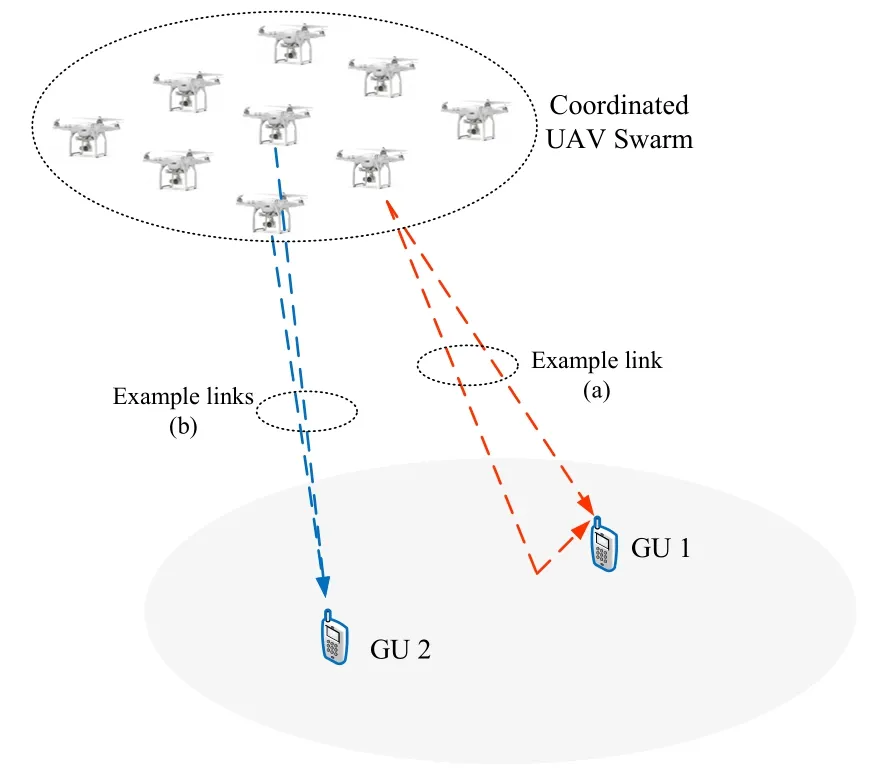
Figure 1.UAV swarm-enabled virtual MIMO communication.
In practice,it has to maintain a minimum inter-UAV distance to avoid collision.The distance is likely to be larger than half wavelength, which, in the conventional propagation environments where scattering is rich, will result in uncorrelated channel links.However,the following facts may render different UAV-GU links actually correlated:
·Sparse Scattering:The UAV-GU link is usually dominated by a LoS path and a ground-reflection path[18],as shown by the example link(a)in Figure 1.
·3D Array and Propagation:Due to the 3D structure of the virtual MIMO array,different UAV-GU links may have very similar angles of departure(AoD)even when the inter-UAV spacing is large,as shown by the example links(b)in Figure 1.
Owing to these facts, the virtual MIMO channel formed by a UAV swarm will be spatially correlated.Importantly,the correlation property in such a system can be dynamically controlled by adjusting the relative positions of UAVs in the swarm.In other words, the virtual MIMO array structure is configurable.Given the locations of GUs in a network,it is possible to find an optimal UAV swarm pattern to get desired correlation property of the virtual MIMO channel, which is beneficial for A2G data transmission.To this end,channel modeling and spatial correlation analysis for the considered system are necessary.
III.PROPOSED CHANNEL MODEL
Considering two major paths of the A2G channel,namely the LoS path and ground reflection path,we first propose a geometric ray superposition-based channel model for the UAV swarm-enabled virtual MIMO system in this section.The model is established on basis of a common coordinate system,where the structure of the virtual MIMO array,as well as the positions of the GUs, are defined by their 3D coordinates, respectively.After that, the path length and corresponding phase shifts of every individual links are calculated.For each specific UAV-GU link, the LoS path and ground-reflection path with different phase shifts are superimposed to obtain its channel coefficient, which finally constitutes the entire virtual MIMO channel matrix.
3.1 Coordinate Systems
Two coordinate systems are defined in the modeling,namely the common coordinate system(CCS)and the UAV swarm-oriented coordinate system(UCS),as described in Figure 2.The UCS is defined by three orthogonal unit basis vectors, namely ni,i= 1,2,3,with its origin denoted byo′.Consider a multi-layered swarm structure,where the UAVs in each layer form a virtual UPA.In this case,ni,i=1,2,3 are defined on the three sides of the swarm cube, respectively.The projection ofo′on the ground is denoted aso, which is considered as the origin of the CCS.The length ofoo′,denoted asH,describes the deployment height of the swarm.The line that connectso′andois defined as thez-axisof the CCS,stemming from which,three basis vectors for the CCS,nx,nyand nz,are defined.
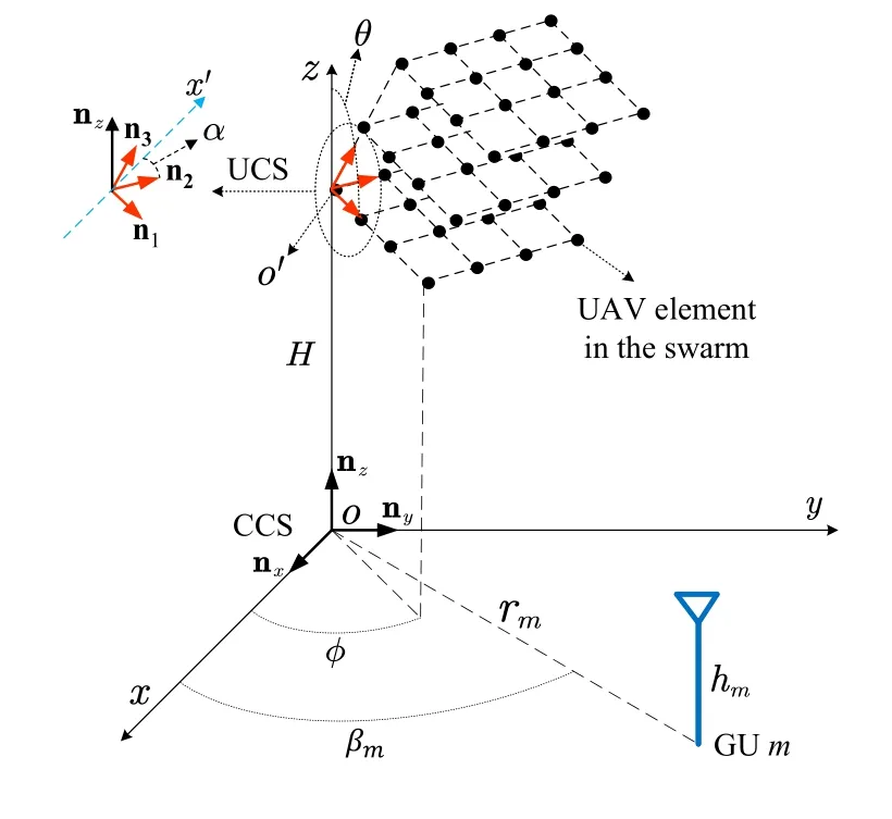
Figure2.Description ofthe CCSand the UCS.
The orientation of n1is described by two angles,θandφ,whereθis the angle between n1and thez-axis,andφis the angle between the projection of n1on thex-o-yplane,and thex-axis.For n2,it is restricted in the plane perpendicular to n1,therefore only one parameter is sufficient for describing its orientation.For this purpose,an auxiliary axisx′is introduced,which is perpendicular to both n1and nz,i.e.,,1then n2can be characterized by a single parameterα,which describes its angle with respect to the direction of nx′.Once n1and n2are determined,n3can be correspondingly obtained.The orientation parameters,θ,φandα,along with the height parameterH,i.e.,the distance betweeno′ando,together describe the relative position of the UCS in the CCS.The relation between the UCS and CCS are described by the follow ing equations:
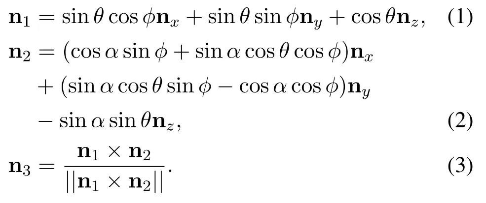
For a certain UAV in the swarm,its coordinates vector in the UCS can be conveniently described by linear combination of ni,i=1,2,3.Further via(1)-(3),the coordinates can be transformed into the CCS.With the locations of ground users also described in the CCS,the propagation paths between any UAV in the swarm and a given GU can be calculated geometrically,as detailed in the follow ing.
3.2 LoS Channel Modeling
For the ease of exposition,we assume that the UAV swarm forms a multi-layer structure,where in each layer,the UAVs form a virtual UPA.We further assume that the UAVs are uniform ly dispatched along the three directions,where the inter-UAV spacing in the directionsof n1,n2,and n3,are denoted asd1,d2,andd3,respectively.Note that the modeling approach can beeasily extended to arbitrary swarm structures.Consider that the UAV swarm hasN=N1×N2×N3UAV elements,whereNiis the number of UAVs in the direction of ni.For the(n1,n2,n3)-th UAV element in the swarm,whereni∈[1,...,Ni],the vector that links the originoand the UAV’s position can be described by

where ki≜di·ni,i=1,2,3(superscript“t”stands for “transm it”,and later “r”is used for “receive”).With the aid of(1)-(3),(4)can be described in the CCS in terms of nx,nyand nz.On the otherh and,for aGUm,whose distance tooisrm,the direction(measured with respect to thex-axis)isβm,and the antenna height ishm,the vector that links the originoand the corresponding receiveantenna is then expressed as

With(4)and(5),the propagation path length between the(n1,n2,n3)-th transmit UAV element,and themth ground receiver,can be calculated as

where||·||represents the Frobenius norm.Correspondingly,the channel coefficient of this LoS link canbe calculated as
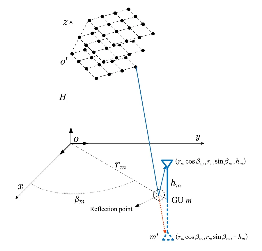
Figure3.Illustration ofthe ground-reflection path.

whereλis the carrier wavelength.For allni∈[1,Ni],stacking the corresponding coefficient calculated by(7)into a vector,denoted as∈C1×N.This describes the LoS channel vector between GUmand the entire UAV swarm.
3.3 Incorporating the Two-Ray Effect
In addition to the LoS path,the ground reflection path contributes another major component in the A2G transmission.Describing the path shift follows a similar process as that adopted in the LoS channel modeling,while the reflection now needs to be characterized geometrically.
We fi rst identify the length of the reflection path,as illustrated in Figure 3.Know ing that the coordinates of them-th GU is(rmcosβm,rmsinβm,hm),the coordinates of its m irror point(denoted asm′),with respect to the ground plane,is(rmcosβm,rmsinβm,-hm).Therefore,the corresponding path length can be directly obtained as


Stacking the coefficients calculated by(10)foralln1,n2andn3,in the same order as that ofas previously defined,we obtain the channel vector(corresponding to the reflection path)of GUm,denoted as∈C1×N,and the corresponding composite tworay A2G channel of GUmisgiven by

For more precise modeling,different path loss of different channel links,as well as possible reflection loss,can be conveniently added into(11).In practice,since the swarm size is usually much less than the transmission distance,and it usually holds thatH≫hm,different channel links may have very similar path loss inmost conditions.For this reason and for the ease of description,we omit the path loss effectin our following analysis.Furthermore,aswillbe shown later in the simulations,the ground reflection path only has minimal impact on the spatial correlation property of the channel when the GUsare located in the far field region of the UAV swarm,which would be common in our considered environment.
3.4 Practical Extensions:Multipath Fading,Blocking,and UAV Jitter
On the basis of(11),the following extensions can be conveniently made,if a more precise channel model is desired.
·Multipathfading.In addition to the ground reflection path,theremay existmore(weaker)scattering/reflection paths in the environment.In this case,a Rayleigh fading component can be added into(11),together with a power scaling factor controlling its relativestrength ascompared to the LoSand ground reflection paths.
·Inter-UAVBlocking.Whether a UAV-GU link is blocked by the other UAVs in the swarm can begeometrically determined, once the positions of every elements in the network are given.In case of blockage, an additional power attenuation (or shadowing)factor can be introduced to the corresponding channel coefficients described in(11).
·UAV Jitter.The UAVs may have random jittering in practice,which causes random variation in its position.This can be reflected by introducing a random offset vector when describing the UAV position vector in(4).
To incorporate these extensions, measurements of the key parameters are necessary.Specifically,important parameters include: A power scaling factor to describe the multipath fading, a power attenuation factor to describe the inter-UAV blockage,and a variance factor to describe the scale of random position variation caused by UAV jitter.Though these extensions might be important in the performance evaluation for practical system implementations,in the following,we focus on the ideal channel described by(11)to establish a tractable analysis framework for the spatial correlation between different UAV-GU links.
IV.SPATIAL CORRELATION ANALYSIS
In this section, we analyze the spatial correlation between different channel links for GUs located at different positions.Consider two GUs,m1andm2, the spatial correlation between their channel links are described by

where the elements of hmi,i= 1,2,are obtained following(11).Althoughρm1,m2can be calculated with the proposed channel model (once the swarm pattern and the GU locations are given),the calculation complexity will be cumbersome when the number of UAV elements and GUs is getting large.Besides, it is not clear how willρm1,m2be affected by the bulk system parameters such as{θ,φ,H,N1,N2,N3,d1,d2,d2}(the swarm pattern parameters) and{rmi,βmi,hmi}(the GU parameters).For these considerations,we aim to find an alternative representation forρm1,m2,which only depends on the bulk parameters mentioned above,while without the need of calculating every individual channel coefficients in(11).
Fortunately,analytical expression of the spatial correlation coefficient for UPA LoS channels is available in the literature[19].However,in our considered scenario, the two-ray propagation and 3D array structure render the existing results cannot be directly applied.In the following,we first show that the two-ray propagation actually has minimal impact on the spatial correlation, as compared to that in the pure-LoS case; after that, we briefly review the spatial correlation analysis results for UPA LoS channels.With these knowledges in hand, we finally propose a spatial correlation analysis framework, which views the UAV swarm-enabled virtual MIMO as a multi-layer UPA, then extends the results in [19] via coordinates rotation and transformation, to obtain a tractable calculation method for(12).
4.1 The Impact of Two-Ray on Spatial Correlation
When calculatingρm1,m2in(12),two-ray propagation will induce cross-terms in the expression, rendering further simplification very challenging.Nevertheless,as shown by the simulations in Figure 4, the spatial correlation calculated with two-ray channel and pure LoS channel match well with each other.This observation implies that the ground reflection ray can be omitted in the calculation ofρm1,m2to simplify the analysis.
In the following, we try to provide an explanation for Figure 4.As directly analysingρm1,m2, taking into account every individual path from every UAV element, is very challenging, we focus on a simplified assumption that the GUs are located in the far field of the swarm.Note that this assumption would be common in UAV communications,where the transmission distance in general will be large.In this case,the channel vector can be well approximated by the array steering vector.For ULA withNantenna elements and for a path in the direction of (θ,φ),2the corresponding 1×N-sized steering vector is expressed as

wherenis the antenna index,Δdis the inter-antenna spacing.Note that for the LoS and reflection paths,they have the sameθin (13), whileφwill be different.However,as the GUs move farther away from the swarm,the difference inφwould be reducing,and the steering vectors corresponding to these two paths tend to be the same.Further considering the phase reversal of the reflection path,a common-πphase will be added to all the elements in its corresponding steering vector.This, however, will not affect the correlation coefficient calculation in (12).The conclusion also holds for the 3D array structure described in Figure 3,as its channel vector can be seen as a composition of multiple sub-vectors corresponding to multiple ULAs.
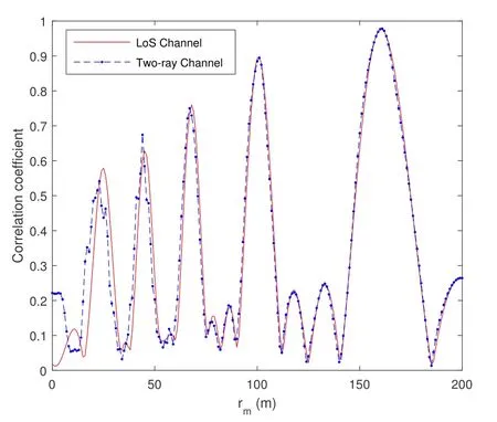
Figure 4. Comparison of correlation coeffcient obtained with the LoS and two-ray channels.UAV swarm parameters: 1×4×4, inter-UAV spacing: 1 m, H = 50 m; GU parameters: m1 coordinates: (5,rm,4), m2 coordinates:(-5,rm,4).
4.2 Spatial Correlation Analysis for UPA LoS Channel
Omitting the reflection path,existing results of correlation analysis for pure LoS channels can be applied.In[19],analytical expression of the spatial correlation is available for UPA LoS channels.The results are first reviewed in the following, and later extended to our considered scenario in the subsequent subsection.
According to[19],for an UPA transmitter(Tx)and an UPA receiver (Rx), the correlation coefficient between the channel vectors to two different receive antennas,aandb(whose two-dimensional indices in the receive UPA are (m1a,m2a) and (m1b,m2b), respectively),is given by

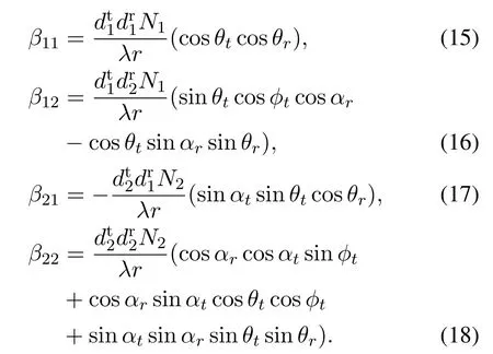
The involved parameters are defined as shown in Figure 5, where the orientation of the Tx/Rx UPA is defined by two principal directions,,i= 1,2.Taking the Tx UPA for example,nt1is characterized by a parameter set{θt,φt}, while nt2is characterized by a parameterαt,following a similar procedure described previously in Section 3.1.Furthermore,dtianddriare the inter-antenna spacing in thei-th principal direction of the Tx/Rx UPA,respectively,andNiis the number of antenna elements in thei-th principal direction of the Tx UPA.Note that the above parameters are defined in a coordinate system, where they-axis is defined as the line that links the left-bottom corner point of the Tx UPA and Rx UPA(the coordinate system is denoted as UPA-CS hereafter).
Note that the result in (14) cannot be directly applied to our considered channel model,for the following reasons:
1.The UPA-CS defined in Figure 5 is different from the CCS and UCS adopted in our channel model,previously defined in Section 3.1.Therefore, in order to obtain the parameters required for the calculation of(14), coordinates transformation is necessary.
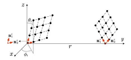
Figure 5.Illustration of the UPA-CS([19]).

Figure 6. Eigenvalue distribution vs.transmission distance to GUs.
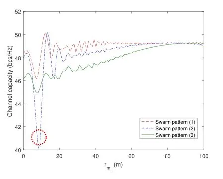
Figure 7.Channel capacity vs.transmission distance to GUs.
2.Different from the scenario in[19]where a single UPA-UPA channel link is considered, the UAVswarm in our considered model forms a multilayered array structure.Besides,in order to apply(14),we need to view different GUs at different locations as elements in a(virtual)receive UPA.
To this end,the detailed coordinate translation and rotation process are described in the follow ing subsection.
4.3 Spatial Correlation Analysis for the UAV Swarm-enabled VirtualM IMO Channel
In order to calculate(12)with the aid of(14),we fi rst view the UAV swarm-enabled virtual M IMO channel as amulti-layer UPA.Specifically,the 1×N-sized channelvector for GUmican bew ritten as


where

Now,the result in(14)can be used in the calculation of(21).However,to obtained the parameters required in(14),we need to transform n1,n2and n3from the CCS to the UPA-CS fi rst.
Without loss of generality,we set the receive antenna of GUm1as the origin of the(virtual)UPA Rx.Denotea 3D coordinatesvector in the original CCS asC,the transformation is conducted with the following three steps:
1.CoordinateTranslation:

2.CoordinateRotationStep1:RotateCclockw ise around thez-axis of the CCS,with degree1,i.e.,
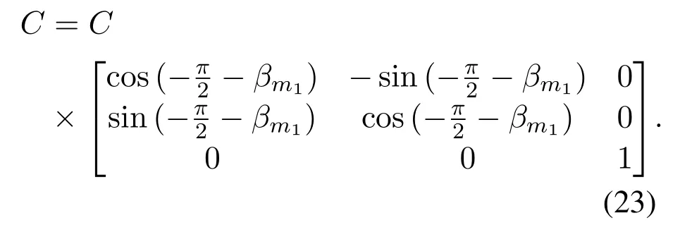
3.CoordinateRotationStep2:After coordinate rotation step 1, further rotateCclockw ise around theyaxis with degree arctan, as described in (24).

With these three steps,given any key vectors in the originalCCS,their representations in the UPA-CScan be conveniently obtained.Correspondingly,the key parameters that are required in the calculation of(21),e.g.,θt/r,φt/r,andαt/r,can be derived.The spatial correlation between any two GUs can be then obtained using(20).
As explained previously,the proposed correlation coefficient calculation method only depends on bulk system parameters,hence its calculation complexity can be greatly reduced especially when there exist a large number of UAVs and GUs in the network.Based on the proposed method,it is possible to optimize the UAV swarm pattern(i.e.,the structure of the 3D virtual M IMO array),to get a desired correlation property of the channel and enhance the transmission per-formance.
V.SIMULATION RESULTS
In this section, based on the proposed channel model and the correlation coefficient calculation method,we conduct various simulations to show the impact of the configurable virtual array structure,on key system performance metrics such as the eigenvalue and condition number distribution,the channel capacity,and the spatial correlation map.In all simulations,the carrier frequency is set to be 5 GHz.The inter-UAV spacing,if not otherwise specified,is set to be 1 m.
5.1 Eigenvalue Distribution and Channel Capacity
We first investigate the impacts of swarm pattern, altitude, and transmission distance on the eigenvalue distribution of the corresponding virtual MIMO channel.Considering that the UAV swarm is consisted ofN= 256 UAV elements, we consider three different swarm patterns in terms ofN1×N2×N3, namely:(1) 4×4×16, (2) 16×4×4, and (3) 4×16×4.For the swarm orientation,we set n1= nx,n2= ny,and n3= nzin the simulations.As an example, 4 GUs(mi,i= 1,...,4)are uniformly spaced on a line which is perpendicular to they-axis of the CCS (and towards the positive direction of thex-axis),with GUm1located on they-axis.The inter-GU spacing is 2 m.With (11), a 4×256 virtual MIMO channel can be generated given the altitude of the UAV swarm,H,and the distance between GUm1and the origin,rm1,are determined.
We first fixH= 100 m and show the distribution of four eigenvalues(λi,i= 1,...,4)vs.rm1in Figure 6.The simulations are conducted as follows: First,the channel vectors of four GUs are stacked into a 4× N-sized virtual MIMO channel matrix H, then eigen-decomposition is conducted for HHHand the four eigenvalues are recorded and described in the figure.Later in Figure 7,the channel capacity is also calculated using H, considering equal power allocation among GUs.Note that the channel capacity evaluated in Figure 7 actually assumed full cooperation among GUs.It can be seen as a performance upper bound,and allows us to focus more on the impact of swarm pattern, while the results are irrelevant to particular multiuser precoding schemes.
As shown in Figure 6,the transmission distance has significant impact on the eigenvalue distribution.For all three considered swarm patterns, there exist different transmission distances that the four eigenvalues tend to be the same,i.e.,the virtual MIMO channel becomes uncorrelated.Notably, the swarm pattern also affects the eigenvalue distribution.The eigenvalues are relatively more concentrate with UAV swarm pattern(1),implying that higher capacity can be obtained with such swarm pattern in this scenario.

Figure 8.Eigenvalue distribution vs.the swarm altitude.
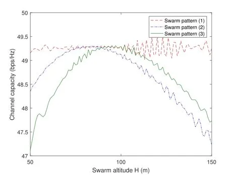
Figure 9.Channel capacity vs.the swarm altitude.
We further demonstrate the channel capacity achieved with three UAV swarm patterns in the same scenario in Figure 7, where it is confirmed that the swarm pattern(1)in general achieves the highest channel capacity in this scenario.3For swarm pattern (2),a deep fading region appears when the transmission distance is around 10 m,as highlighted by the red circles in Figure 6b and Figure 7.This might stem the destructive two-ray superposition in this area.As also shown in Figure 4, this implies that when the transmission distance is very small, ignoring the groundreflection path might induce error in the performance evaluation.
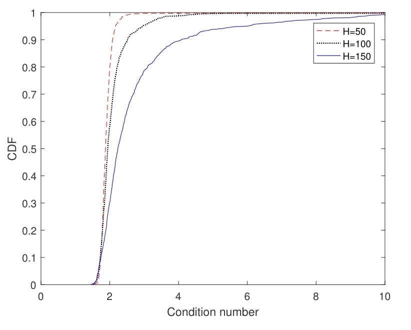
Figure 10.CDF of the condition number for randomly distributed GUs.
In the next,we further fixrm1=100 m and demonstrate the eigenvalue distribution and channel capacity with different UAV swarm altitude,H.The results are provided in Figure 8 and Figure 9, respectively.As shown by the figures,optimal UAV swarm altitude exist to minimize the channel correlation and maximize the capacity.Among the considered three swarm patterns, swarm pattern (1) in general has the least dispersed eigenvalues, and its achieved capacity is less sensitive to the swarm altitude.
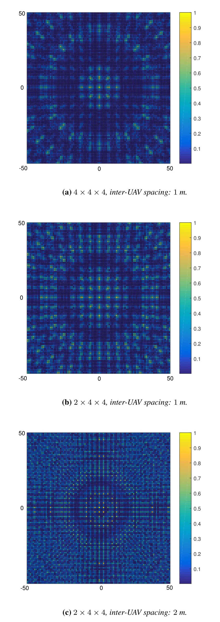
Figure 11.Spatial correlation map with different UAV swarm patterns.
According to these simulations, in practice, when the locations of GUs in a network are fixed and known,it is possible to find a best swarm pattern among some candidate swarm pattern set (which, for example, maximizes the channel capacity), with the aid of the proposed channel model.Furthermore, the spatial correlation analysis framework proposed in Section IV could be used to facilitate the development of swam pattern selection algorithms with lower complexity, which, however, is beyond the scope of this paper and left for further research.
5.2 Condition Number Distribution
We further consider a more general scenario with randomly distributed GUs, and investigate the virtual MIMO channel property in terms of the channel condition number.The condition number is defined as the ratio between the largest and smallest eigenvalues,where the eigenvalues of the virtual MIMO channel are obtained in the same way as previously described in Section 5.1.In this case,smaller condition number implies less correlated channels,which is desirable for multiuser MIMO transmission.In the simulation, 10 GUs are randomly distributed within a circle area centered ato.The results are measured over 1000 drops,while for each drop,the locations of 10 GUs are independently generated.Given the locations of the GUs,the virtual MIMO channel is generated according to(11), and its condition number is calculated.According to 1000 condition numbers obtained in the 1000 simulation drops,the cumulative distribution function(CDF)of the condition number is described in Figure 10.
In the figure, we consider a swarm pattern of 4×4×16 as example.The CDF is depicted for different swarm altitudes,H.It is shown that for this scenario,lower swarm altitude leads to smaller condition numbers,i.e.,the CDF curve moves leftwards.In this case,the virtual MIMO channel will be less correlated(in stochastic means), which is preferable for multiuser transmission.The optimal swarm altitude may vary with different swarm pattern,different number of GUs,as well as different target area.Nevertheless,for any interested scenario,similar results as that in Figure 10 can be easily obtained with the proposed channel model in(11).
5.3 Spatial Correlation Map
At last, we extend the discussion to the 2Dx-o-yplane.Consider two GUs,m1andm2,we fix the location of GUm1to(0,0,0),and let the location of GUm2vary in a square area with side length 100 m,and with the originobeing its center.For every location ofm2, the two virtual MIMO channels are generated with(11),accordingly,the spatial correlation between the channel links ofm1andm2is calculated and illustrated on thex-o-yplane.We term the result as a spatial correlation map in the following.
For different UAV swarm patterns, we describe the corresponding spatial correlation map in Figure 11.As shown in the figures, there exist high correlation regions distributed in the target area, and the distribution of these high correlation regions is affected by the swarm pattern (including both the virtual array structure and the inter-UAV spacing).The spatial correlation map can be useful in the design of UAV swarmenabled virtual MIMO communications.For example, in an overloaded scenario where the number of GUs is larger than the number of UAV elements,user selection can be conducted.In this case, the system designer could generate spatial correlation map for a target GU,then schedule the GUs which are located in its low correlation areas for multi-user transmission.The process should be conducted sequentially for every GU,to guarantee that the correlation between any GU pair is lower than a tolerant threshold.
VI.CONCLUSIONS
In this paper, we proposed a geometric ray superposition-based channel modeling approach for UAV swarm-enabled virtual MIMO communications.Based on the channel model, we further provided a spatial correlation analysis framework,with which the spatial correlation coefficient can be calculated with only bulk system parameters, such as the swarm pattern,orientation,altitude,and the GU locations.With the aid of the proposed channel model and via extensive simulations, we have shown that the eigenvalue distribution,capacity,condition number distribution of the virtual MIMO channel can be significantly affected by the swarm pattern,and it is possible to flexibly configure a desirable swarm pattern to achieve better communication performance.At last, we investigated the spatial correlation map for a target GU,and discussed its possible applications in UAV swarm-enabled virtual MIMO communication design.
ACKNOWLEDGEMENT
This work was supported by the National Key Research and Development Program of China(2018YFA0701602), the National Natural Science Foundation of China(NSFC)under Grants 61941104,61921004, 62171240, 61771264, and the Key Research and Development Program of Shandong Province under Grant 2020CXGC010108.
NOTES
1When applied to vectors,“×”represents vector cross product.
2With a bit abuse of symbols,we define here in this subsectionθandφas the azimuth and vertical incident angles of the path,respectively.
3Large scale path loss is ignored in the simulations,as we focus on showing the impact of spatial correlation on the channel capacity.
- China Communications的其它文章
- GUEST EDITORIAL
- Reducing Cyclic Prefix Overhead Based on Symbol Repetition in NB-IoT-Based Maritime Communication
- Packet Transport for Maritime Communications:A Streaming Coded UDP Approach
- Trajectory Design for UAV-Enabled Maritime Secure Communications:A Reinforcement Learning Approach
- Hybrid Satellite-UAV-Terrestrial Maritime Networks:Network Selection for Users on A Vessel Optimized with Transmit Power and UAV Position
- Energy Harvesting Space-Air-Sea Integrated Networks for MEC-Enabled Maritime Internet of Things

