
Identify fine microstructure of multifarious iron oxides via O K-edge EELS spectra
2022-09-15 03:11JunnanChenYujieQiMingLuYimingNiuBingsenZhang
Chinese Chemical Letters 2022年9期
Junnan Chen, Yujie Qi, Ming Lu, Yiming Niu, Bingsen Zhang,∗
a Shenyang National Laboratory for Materials Science, Institute of Metal Research, Chinese Academy of Sciences, Shenyang 110016, China
bSchool of Materials Science and Engineering, University of Science and Technology of China, Shenyang 110016, China
c Key Laboratory of Functional Materials Physics and Chemistry of the Ministry of Education, Jilin Normal University, Changchun 130103, China
ABSTRACT Relying on the electron energy loss spectrum (EELS) of metallic elements to obtain microstructure analysis is an investigation method of the reaction mechanisms of transition metal oxides (TMOs) in catalysis,energy storage and conversion.However, the low signal from K shell owing to insufficient electron beam energy, and the complicated electronic structure in L shell of the metal element restrict the analysis of the coordination environment of the TMOs.Herein, density functional theory (DFT) calculation, Fourier transform (FT) and wavelet transform (WT) were employed to probe the relationship between the four individual peaks in O K-edge spectra of iron oxides and the microstructure information (chemical bonds and atomic coordination).The findings show that the peak amplitude ration is in a linear correlation with the valence state of Fe element, and that the coordination number obtained by radial distribution function (RDF) is favorably linearly correlative with that from the standard coordination structure model.As a result, the quantitative analysis on the change of valence state and atomic coordination in microstructure can be realized by EELS O K-edge spectra.This study establishes EELS O K-edge spectrum as a promising pathway to quantitatively analyze the valence state and atomic coordination information of TMOs,and offers an effective method to conduct microstructure analysis via the EELS spectra of the non-metal element.
Keywords:EELS ELNES EXELFS Transition metal oxides DFT Wavelet analyze
Transition metal oxides (TMOs) have been received widespread attention as catalysts or electrode materials with the merits of various valance states and multiphase transition [1–4].To explore the reaction kinetics of a catalytic and electrode process, the analysis on microstructural transformation of TMOs is absolutely essential [5,6].In general, XRD andin-situXRD are utilized to obtain the phase transformation information.X-ray photoelectron spectroscopy (XPS) and X-ray absorption fine structure (XAFS) are employed to investigate the evolution of valence state and coordination environment for characteristic elements of TMOs.But these approaches cannot satisfy the collection of the local structure signal of TMOs [7,8].Electron energy-loss spectroscopy (EELS) based on transmission electron microscope (TEM) platform could realize the local acquisition of the chemical information on distribution,valence state and coordination environment of characteristic elements of TMOs with a high spatial resolution [9].For instance,the phase transformation behavior of V2O5underin-situvacuum heating and the strong metal-support interaction in Au/TiO2catalysts have been studied by the EELS spectrum to reveal the process mechanisms [10–12].However, the combination of low signal from K shell and complicated electron structure in L shell of the metal element of TMOs restrict the analysis of coordination environmentviacollecting the EELS spectra of metal element [13].Further, a limitation appears on the exploration of the microstructural change of TMOs.Due to the strong bonding between the transition metal atom and the O atom in TMOs, the O EELS spectrum can be collected to realize a comprehensive investigation of the local microstructure of TMOs.
Herein, based on O K near-edge structure, the O K-edge spectra of iron oxides (FeO, Fe3O4,γ-Fe2O3,α-Fe2O3) have been collected as examples to model the reaction process at different stages.The Fourier transform (FT) and wavelet transform (WT) methods have also been used to analyze O K-edge extended energy-loss fine structures (EXELFS), to construct the relationship between characteristic peaks and microstructure, which provides an effective route to reveal the fine microstructure of TMOsviathe EELS spectra of the non-metal element.
The O K-edge and Fe L-edge spectra of iron oxides (FeO, Fe3O4,γ-Fe2O3,α-Fe2O3) are shown in Fig.1.There are two peaks in L-edge spectra of iron oxides in Fig.1b, which are located in the ranges of 710−720 eV and 725−735 eV, respectively.This phenomenon originates from Fe electrons transition from 2p3/2and 2p1/2orbitals to unoccupied 3d states.With the increase of valence state for Fe in iron oxides, the L2and L3peaks move toward higher energy and the white-line ratio of Fe L2to Fe L3also increase.In the Fig.1a, there is no distinct difference between the O K-edge spectra of iron oxides with different valence states.There are four individual peaks (a–d) in O K-edge spectra, the relative intensity of peak a (prepeak), located in the range below 540 eV, increases significantly when iron oxide is changing from FeO toα-Fe2O3.It corresponds to the transition from the O 1s core state to the unoccupied state of O 2p hybridized with Fe 3d states.As reported in the literature [14,15], the intensity of peak a is closely related to the occupancy number of the Fe 3d orbital, the coordination geometry around the O atom, and the bond length between O atom and nearest neighbor Fe atom.The Peak b is emerged at around 543 eV,generally speaking, resulted from the O 2p unoccupied state hybridized with Fe 4s and 4p states.The relative weak peak c located at around 550 eV and the broad peak d centered at around 565 eV can also be observed in Fig.1a.However, there exists a remarkable controversy on whether peak c and peak d belong to EXELFS or energy-loss near-edge structure (ELNES) [15,16].There is one point of view, peak d stems from the backscattering in the first shell of Fe atoms and peak c is attributed to the backscattering in the second shell of O atoms [15].
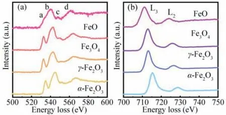
Fig.1.The O K-edge spectra (a) and Fe L-edge spectra (b) for iron oxides (FeO,Fe3O4, γ-Fe2O3, α-Fe2O3).
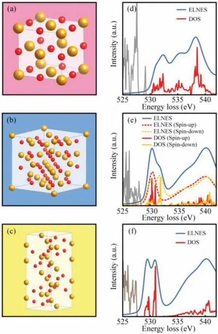
Fig.2.The crystal structures and corresponding simulations of O K-edge ELNES spectra for FeO (a, d), Fe3O4 (b, e) and α-Fe2O3 (c, f).
Due to random arranged oxygen vacancies, the accurate crystal model ofγ-Fe2O3is hard to be set up.In consideration of similar crystal structure and electronic structure betweenγ-Fe2O3and Fe3O4, the O K-edge ELNES simulation of Fe3O4can be substituted for that ofγ-Fe2O3.In order to explore the origin of these characteristic peaks, the crystal models of FeO, Fe3O4andα-Fe2O3have been established, as shown in Figs.2a–c.Based on these structures of common iron oxides, the O K-edge ELNES spectra for these three iron oxides have been simulated through WIEN2k, as shown in Figs.2d–f.The electron configurations of the associated oxygen polyhedral ligands are shown in Fig.S1 (Supporting information) [17].The FeO is an antiferromagnetic material with NaCl type structure (Fig.2a).There are three peaks centered at 532, 536 and 539 eV in a simulation of FeO ELNES spectra (Fig.2d), and the peaks located at 532 and 539 eV correspond to peak a and peak b in O K-edge spectra (Fig.1a).However, there is no peak in Fig.1a corresponding to the peak at 536 eV observed in the O K-edge spectra in Fig.2d.Moreover, the position of peak b from the simulation is lower than that from the experimental spectra.This is due to the presence of cationic defect sites within FeO as a nonstoichiometric compound, which leads to a slightly higher average valence of Fe than 2+.The Fe3O4is a typical ferrimagnetic material with an inverse spinel structure, in which the oxygen ions form a face-centered cubic lattice and the Fe atoms occupy tetrahedral and octahedral sites.Two different sublattices are formed by these Fe atoms in different oxygen polyhedral center sites, which are coupled in antiferromagnetic forms (Fig.2b).In the simulation of Fe3O4, there are two peaks centered at 530 eV and 540 eV (Fig.2e), corresponding to peak a and peak b in experimental spectra of Fe3O4, respectively.The spin polarization effect on the spectral structure is also shown in Fig.2e.Compared to the spin-up spectra, the peak a of spin-down spectra appears splitting, which is similar to the feature ofα-Fe2O3simulated spectra.Meanwhile,theα-Fe2O3has a hexagonal structure with oxygen close stacking,and exhibits antiferromagnetism and relatively high thermal stability (Fig.2c).Similar to the case of Fe3O4, the simulated spectrum ofα-Fe2O3also has two peaks centered at 530 and 540 eV, corresponding to peak a and peak b.The difference is that the simulated peak a ofα-Fe2O3appears splitting (Fig.2f).Although this phenomenon could not be observed in the experimental spectra due to low energy resolution, it is feasible to observe split peak by continuously improving the resolution.
In the Fig.S1, the diagrams of molecular orbital for octahedral ligands of (FeO6)10−, (FeO4)5−and (FeO6)9−are shown.Combined with this figure and density of states calculations, the influence of electronic structure on the O K-edge spectra can be further understood.The spin-up states of spin-up polarized Fe atoms and spindown states of spin-down polarized Fe atoms are both under Fermi energy, it is in accord with the character of high-spin electronic configurations.In other words, the suborbitals of d electron are occupied by at least one electron in iron oxides.The O atoms around iron atom not only split d electron orbital into egand t2gstates,but also hybridize with partial energy-level (3d, 4s and 4p states)of Fe atom.The energy states of lone-pair electrons in O atoms are denoted asσ.In the oxygen octahedral ligands ((FeO6)10−and(FeO6)9−), six undifferentiatedσstates are hybridized with the eg,4s and 4p states of Fe atom, to form bonding orbital a1g, t1u, eg,and antibonding orbital a1g∗, t1u∗, eg∗.Without hybridization, Fe t2gstate forms a non-bonding orbital.As for oxygen tetrahedral ligand ((FeO4)5−), four undifferentiatedσstates are hybridized with the 4s and 4p states of Fe atom, to form bonding orbital a1g, t1u,and antibonding orbital a1g∗, t1u∗.Meanwhile, Fe t2gand egstates form two non-bonding orbital without hybridization.From these diagrams, the different ligand structures of iron oxides can result in different unoccupied energy state distribution.As shown in Fig.S2 (Supporting information), the O 2p orbitals and Fe 3d orbitals of FeO, Fe3O4andα-Fe2O3with different spin directions are clearly presented.By analyzing the electronic structures of these three iron oxides, it can be found that unoccupied states of O 2p electron, which hybridized with Fe 3d electron, are mainly distributed above the Fermi energy 0—5 eV.This indicates that the K-shell ionization edge from threshold energy 0—5 eV (peak a structure) could be caused by electron transferring from 1s orbital to the antibonding orbital formed by Fe and O hybridization.It is confirmed that peak a structure in oxygen ELNES is related to the Fe-O bond.
In FeO, Fe atoms have four electrons in the t2gorbital, which means that electron numbers of dxydyzdxzorbital are not equal,causing the t2gorbital to be split (known as the Jahn-Teller effect).This can be seen in Fig.S2a, the spin-up Fe atoms (red line) have two relatively sharp peaks in spin-down states, which appear at occupied states (near Fermi energy) and unoccupied states (about 1.2 eV), respectively.These two peaks both belong to t2gorbital.Some suborbitals, which could be fully occupied, are pulled down in energy until they are near the Fermi energy.Others increase in energy and lead to a decrease in the splitting energy between eg∗and t2gorbitals.With only three electrons in t2gorbit, there is no Jahn-Teller effect inα-Fe2O3.Therefore, the phenomenon that two relatively sharp peaks appear above Fermi energy can be observed in Fig.S2c, corresponding to eg∗and t2gorbits, respectively.The structure of Fe3O4is relatively complex, including not only two kinds of oxygen octahedral ligand structures (FeO type andα-Fe2O3type), but also oxygen tetrahedral ligand structure.In Fig.S2b, we can observe that the unoccupied energy state of spin-up Fe atom (located at the center of octahedral ligand) has both the features ofα-Fe2O3and FeO.The partial t2gstates reduce energy and form occupied states (FeO feature), t2gand egstates are discrete and easy to identify (α-Fe2O3feature).In the spin-down Fe atom (located at the center of tetrahedral ligand), the t2gorbital energy is higher than egorbital energy, however, the splitting energy is smaller than that in octahedral ligand.Therefore, the splitting degree of peak a for Fe3O4is between the two cases of FeO andα-Fe2O3due to the overlapping electron structures from these different ligands.
The near edge fine structure simulation results of iron oxides do not reveal the origin of peaks b, c, and d, suggesting that these peaks may belong to extended edge fine structure.This part of the spectral structures originates from interference between the ejected electron of the excited atom and the backscattered electron from the neighbor atom.It is beneficial to analyze the extended edge fine structure for revealing the coordination of neighboring atoms around oxygen atoms.In order to show the coordination of oxygen atom, the radial distribution function (RDF) obtained by Fourier transform (FT) is used to describe the distribution of neighbor atoms.Firstly, the oscillating part of EXELFSχ(k) is obtained by the piecewise spline function fitting method with 5thorder [13,18].Then, before Fourier transform,χ(k) is reduced noise,and the de-noising effect is shown in Fig.S3 (Supporting information).As the backscattering amplitude factor presents a strong dependence on the atomic number Z, different atomic backscatters from the heavy atom and light atom are localized in the different k-space.Therefore, the type of atoms can be distinguished byR∼ktwo-dimensional relationship diagram of kn-weighted EXELFS [19–21].To achieve this purpose, wavelet transform (WT) is applied for obtaining ofR∼ktwo-dimensional relationship diagram.
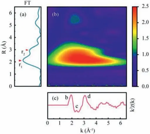
Fig.3.The radial distribution function (a), wavelet analysis contour (b) and oscillating part of EXELFS (c) of O atoms in α-Fe2O3.
The Fourier transform (FT) and WT analysis results ofα-Fe2O3are displayed in Fig.3, and corresponding results for FeO, Fe3O4andγ-Fe2O3are presented in Figs.S4-S6 (Supporting information),respectively.Takingα-Fe2O3as an example, the RDF (Fig.3a) could be obtained by the oscillation signal which isχ(k) spectrum multiplied by window function W(k) and amplitude modulation factork(Fig.3c).Although the distance of neighbor atoms can be determined by the peaks in RDF, some fake peaks derived from the data truncation, would appear in the curve.Therefore, the wavelet analysis diagram that representing the relation between interatomic distanceRand wave vectork, would be helpful in identifying the actual neighboring atoms.In the wavelet analysis results (Fig.3b),a lobe is localized in theΔk∼(0–6.5) ˚A−1andR∼(1.5–3.5) ˚A range.By changing window function W(k)range, wavelet analysis results of two regions (with or without b, c, and d structure) were obtained.In the region including b, c, and d structure (Fig.S7b in Supporting information), a lobe centered onR=2.5 ˚A could be found in the wavelet analysis contour.The result does not suggest that there are some neighbor atoms at 2.5 ˚A from the central O atom.In fact, this situation is due to the common effect of neighbor atoms backscattering at 2 ˚A and 3 ˚A.However, the broadening effect due to the extreme small range, would cause an overlap of two lobes overlapping.In the region without b, c, and d structure (Fig.S7c in Supporting information), only a lobe centered onR=2 ˚A could be found in the wavelet analysis contour.This indicates that lobe in Fig.3b is made of the overlapping of two small lobes.By comparing with the center of two lobes, peaks located at 2 ˚A and 3 ˚A can be determined that they are corresponding to the nearest neighbor Fe atom and O atom, respectively.The similar results could also be obtained in the cases of FeO, Fe3O4andγ-Fe2O3, as shown in Figs.S4-S6.Overall, the O K edge extended fine structure is mainly caused by the backscattering of the nearest Fe atom.In addition, the b, c and d peaks are affected by the backscattering of the second neighbor O atoms.
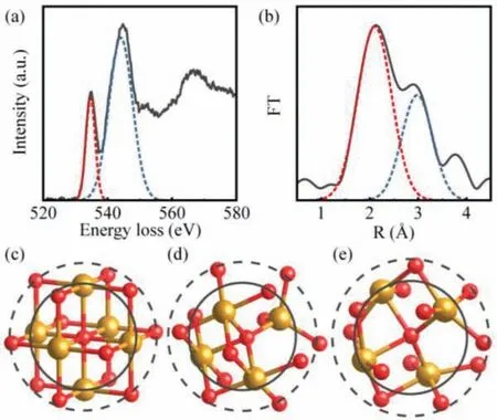
Fig.4.The fitting diagram of O K-edge structures (a) and radial distribution function (b) in α-Fe2O3 nanorods.The coordination structures of oxygen atom in FeO(c), Fe3O4 (d) and α-Fe2O3 (e).
Based on the analysis above, an effective method could be proposed in order to analyze oxides microstructure quantitatively.It is easy to obtain the valence state from near edge structure, which reflects the electronic structure of the material.The basic edge shapes of the O K spectrum are saw tooth, and with additional fine structures.Since the peak a reflects the chemical bonding between oxygen and transition metal, if more d electrons of transition metals are involved in bonding, more antibonding orbitals will be produced accordingly.In short, the intensity of peak a relative to the ionization edge main structure is positively correlated with the valence state of transition metal.For convenience of use, instead of using the hydrogenic model or Hartree-Slater method to calculate the basic shape of O K-edge, it can be used to estimate valence state by simply measuring the peak amplitude ratio of peak a to peak b.Although, the peak b is affected by the electronic structures of oxide, the body is mainly influenced by the inelastic scattering of incident electrons.The relative amplitude between peak a and peak b has been measured by Gaussian fitting method, shown in Table S1 (Supporting information).In Fig.4a, the fitting diagram ofα-Fe2O3is displayed.The analytic result indicates that there is a linear correlation between the relative amplitude and the valence state of Fe, and that the relative amplitude can be considered as the calibration for a valence state.The extended edge structure reflects the coordination information of atoms around oxygen atom,consequently, the ratio of the nearest neighbor atoms to the second nearest neighbor atoms around the oxygen atom can be obtainedviaGaussian fitting (Fig.4b), the analysis result is listed in Table S2 (Supporting information).Fig.4b shows the fitting diagram of the radial distribution function inα-Fe2O3.The coordination structure models of oxygen in different iron oxides have been established, as shown in Figs.4c–e, to investigate the relationship between the result and oxygen coordination.Therefore, the atoms near oxygen atoms from these iron oxides are focused on during the research process.The coordination structure of FeO with 6 nearest neighbor iron atoms and 12 second nearest neighbor oxygen atoms distributed around the central oxygen atom is presented in Fig.4c, and the valence state of all iron atoms is +2.Fig.4d shows the coordination structure of Fe3O4, in which the central oxygen atom is surrounded with 4 nearest neighbor iron atoms and 12 second nearest neighbor oxygen atoms.The distances from four iron atoms to the central oxygen atom are different, one iron atom is farther away from the central oxygen atom than the other three iron atoms.This iron atom is in the center of the tetrahedral ligand and the other three iron atoms are in the center of the octahedral ligand.As for the coordination structure ofα-Fe2O3, which has 4 nearest neighbor iron atoms and 12 second nearest neighbor oxygen atoms surrounded the central oxygen atom, the distances between four iron atoms to the central oxygen atoms are identical.Considering that FeO as a nonstoichiometric compound, its actual structure can be expressed as Fe0.83O∼Fe0.95O due to a large number of cation defects.So this means that the ratio of coordination number needs to be corrected to 1.349∼1.544 for FeO model.Although the ratio of coordination number obtained by RDF function is not equal to that from the coordination structure model, there exists a linear correlation between them.When these experimental values multiplied by about 1.176, it is that these experimental values are in good agreement with the values in the model.Although the nature of the coefficient 1.176 is not yet clear, however, the value of the coordination number can be accurately determined by using standard samples in the process of practical application,thus avoiding the determination of this coefficient.Therefore, the quantitative analysis on the change of atomic coordination in microstructure can be realized by extended edge fine structure.In order to reveal the coordination structure of oxygen atoms more accurately, the future research and investigation would be required.
In summary, an approach of resolving EELS spectra to analyze fine microstructures of TMOs by the O-K than Fe-L was proposed.Relied on the corporation of DFT calculation, Fourier transform (FT)and wavelet transform (WT), the relationship between electron energy loss O K spectra and microstructures for iron oxides was investigated in detail.The origins of four individual peaks in O Kedge spectra have been interpreted by the comparison between experimental spectra and simulated spectra, and the contrasts among wavelet analysis contours of O atoms with different wave vector ranges.Consequently, the quantitative analysis on the change of valence state and atomic coordination in microstructure can be realized by the near edge structure and extended edge fine structure,respectively.This analytical method based on EELS O K-edge spectra could obtain valuable structural information for TMOs, which encourages the quantitative structure-activity relationship building.Furthermore, this methodviaEELS spectra of non-metal element can expand the research on the microstructures of TMOs.
Declaration of competing interest
The authors declare no conflict of interest.
Acknowledgments
The authors gratefully acknowledge the financial support provided by the National Natural Science Foundation of China (Nos.22072164, 51932005, 21773269, 52161145403), Liao Ning Revitalization Talents Program (No.XLYC1807175), and the Research Fund of SYNL.
Supplementary materials
Supplementary material associated with this article can be found, in the online version, at doi:10.1016/j.cclet.2021.12.027.
 Chinese Chemical Letters2022年9期
- Chinese Chemical Letters的其它文章
- A review on recent advances in hydrogen peroxide electrochemical sensors for applications in cell detection
- Rational design of nanocarriers for mitochondria-targeted drug delivery
- Emerging landscapes of nanosystems based on pre-metastatic microenvironment for cancer theranostics
- Radiotherapy assisted with biomaterials to trigger antitumor immunity
- Development of environment-insensitive and highly emissive BODIPYs via installation of N,N’-dialkylsubstituted amide at meso position
- Programmed polymersomes with spatio-temporal delivery of antigen and dual-adjuvants for efficient dendritic cells-based cancer immunotherapy