A Reverse-Design Strategy for the Track Error of the Qi Tai Telescope Based on Pointing Accuracy
Na Li*, Baoyan Duan, Xiangyang Li, Bin Zheng, Jiang Wu
Key Laboratory of Electronic Equipment Structure Design, Ministry of Education, Xidian University, Xi’an 710061, China
Keywords:Reverse design Track error Large radio telescope Two-scale model Pointing accuracy
ABSTRACT The Qi Tai Telescope(QTT),which has a 110 m aperture,is planned to be the largest scale steerable telescope in the world. Ideally, the telescope’s repeated pointing accuracy error should be less than 2.5 arc seconds(arcsec);thus,the telescope structure must satisfy ultra-high precision requirements.In this pursuit,the present research envisages a reverse-design method for the track surface to reduce the difficulty of the telescope’s design and manufacture. First, the distribution characteristics of the test data for the track error were verified using the skewness coefficient and kurtosis coefficient methods. According to the distribution characteristics, the azimuth track error was simulated by a two-scale model. The error of the long period and short amplitude was characterized as large-scale and described by a trigonometric function,while the short period and high amplitude error was characterized as small-scale and simulated by a fractal function. Based on the two-scale model, effect of the error on the pointing accuracy was deduced. Subsequently, the relationship between the root mean square (RMS) of the track error and the RMS of the pointing accuracy error of the telescope was deduced. Finally, the allowable RMS value of the track error was derived from the allowable pointing accuracy errors. To validate the effectiveness of the new design method, two typical radio telescopes (the Green Bank Telescope (GBT) and the Large Millimeter Telescope (LMT)) were selected as experimental examples. Through comparison, the theoretical calculated values of the pointing accuracy of the telescope were consistent with the measured values, with a maximum error of less than 10%.
1. Introduction
The five-hundred-meter aperture spherical radio telescope(FAST) was completed in 2016 in Guizhou Province, China, and is the world’s largest and most powerful single-dish radio telescope.Construction of the 110 m fully steerable Qi Tai Telescope (QTT)has now been proposed as part of the Xinjiang Astronomical Observatory in Urumqi, Xinjiang Uygur Autonomous Region, China, and the QTT will be the largest steerable telescope in the world [1,2].While FAST is much more sensitive than the QTT at frequencies below 3 GHz,it has a limited sky coverage;in contrast,the QTT will operate from 150 MHz to 115 GHz with full sky coverage.
The sky coverage and frequency coverage of the QTT will make it a very versatile instrument that can observe many molecular line emissions,observe the Galactic Center,and greatly improve pulsar gravitational wave measurements. The required pointing accuracy for the QTT is 2.5 arc seconds(arcsec),which is extremely difficult to achieve for a telescope structure with a mass of 6000 t,height of 100 m,and reflection surface area of 110 m[3,4].Taking the distribution of the pointing errors of the Large Millimeter Telescope(LMT),located on top of the Sierra Negra mountain in the province of Puebla, Mexico, as an example [5], before the error compensation, the pointing errors induced by the service environment,mechanical calibration, and servo control of the LMT are 10.76, 5,and 7.74 arcsec,respectively[6,7].However,the traditional design idea considers multiple error sources equally; therefore, the final pointing accuracy of the telescope is quite limited [8]. To satisfy the extremely high pointing accuracy requirements in the design of the QTT,the key error source should be identified;then,priority control should be conducted on the key error source.
The structural error of a telescope is the key factor that affects its pointing accuracy.Sources of error mainly involve deformation of the bases, reflectors, or tracks [9]. Welded tracks are the relatively smooth rail joint between single rails made by welding,which makes the overall rail durable. At the cost of a highly difficult welding process, welded tracks are suitable for highprecision and high-load telescopes [10]. However, the processing and welding process of the guide track introduces a random error,the random error mainly includes the micro surface error and the macro track irregularity [8,11,12]. Errors on these two scales can induce error into the azimuth axis and elevation axis of the telescope, which affects the pointing accuracy [13].
In early research on the influence of track error on telescopes,the measured track error data was obtained by means of measuring instruments. Unevenness was directly converted into errors of the azimuth and elevation angles of the telescope by means of the geometric conversion formula [14]. In addition, Pisanu et al.[15] considered the influence of the azimuth frame deformation caused by track error and temperature drift on the pointing accuracy. Kong et al. [16] studied track error test data and performed an experiment to determine the pointing accuracy. The relation between track error and pointing accuracy was then analyzed according to the test data. The influence of nonlinear track error on the pointing performance of the telescope has also been studied[17].Previous research has shown that the track error is a key error source that must be constantly considered in the design,construction,and operating stages of a telescope.The structural error of the track is obviously multiscale, which is not considered in the error modeling. Therefore, an accurate relationship between pointing error and track error has not yet been established. This shortfall is the basis of the reverse-design strategy proposed herein.
Advanced iterative calculations with finite-element modeling(FEM) or a finite difference time domain (FDTD) are often used for surface performance prediction. However, this traditional design process is affected by the inherent error of human guidance.Based on a two-scale error model and the influence mechanism of this error on the telescope pointing, a reverse-design method for designing the track surface is proposed in this study, which can effectively search and optimize the core parameters of the surface structure to achieve the surface characteristics required by users.The model is an effective reverse-design technology for large wheel/rail surfaces, which helps to reduce the amount of calculation and human resources in the traditional surface design, avoid complex professional iterative simulation and parametric scanning research, and serve users who lack mechanical knowledge.
2. Influence of track error on the pointing accuracy of the telescope
2.1. Analysis and verification of the test data attributes of track error
From the results of a numerical analysis of the test data for certain large radioastronomy telescopes, such as the LMT and the Robert C.Byrd Green Bank Telescope(GBT),it can be preliminarily assumed that the track error data of these large telescopes follow a Gaussian distribution [18]. In practical engineering applications,this conclusion should also be verified by test methods, such as the skewness coefficient method and kurtosis coefficient method[19,20]. These two methods are described in detail as follows:
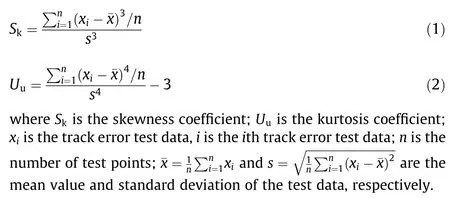
If both the skewness and kurtosis of the uneven test data approach zero, then it can be confirmed that the dataset follows a Gaussian distribution on the whole.For a set of test data samples,if the calculated skewness is positive, the kurtosis presents a bias toward the smaller-value side, as compared with the condition of the dataset following a standard Gaussian distribution.In contrast,if the calculated skewness is negative, the kurtosis presents a bias toward the larger-value side, as compared with the condition of the dataset following a standard Gaussian distribution. If the kurtosis is calculated to be positive,the distribution is relatively sharper than a standard Gaussian distribution.However,if the kurtosis is calculated to be negative, the distribution is relatively flatter than a standard Gaussian distribution. If the test data follow a Gaussian distribution, then the skewness and kurtosis also correspondingly follow a Gaussian distribution, and the mathematical expectation is equal to zero. The root mean square (RMS) values of the skewness and kurtosis can be expressed as follows:

where σsand σudenote the RMS values of the skewness and the kurtosis methods, respectively.
Assuming that the test data of the track error follow a Gaussian distribution, the confidence coefficient α can be set as 0.05(α =0.05). When the skewness coefficient Sk>1.96σsand the kurtosis coefficient Uu>1.96σu,the assumption is invalid and the test dataset does not follow a Gaussian distribution. Otherwise, the assumption holds; that is, the test dataset follows a Gaussian distribution.
2.2. Two-scale model of track error
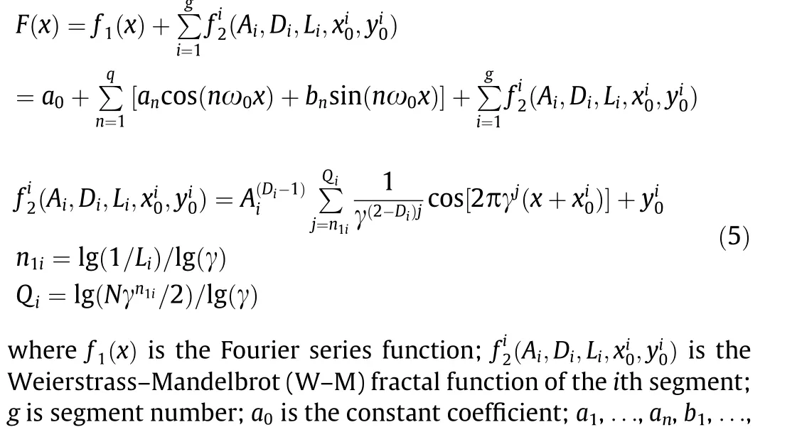
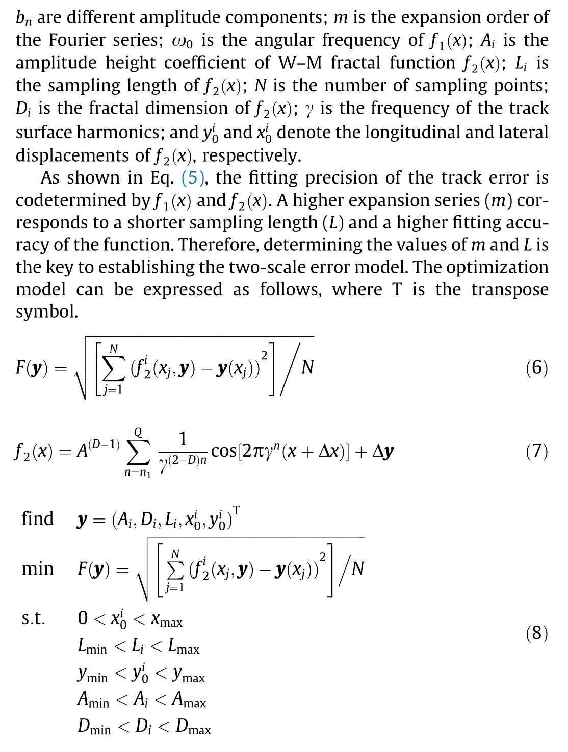
The structural error of the track involves two main aspects:random error from single-track processing and deformation caused by gravity during track service. These two types of errors have different sources and distribution characteristics[21,22].The processing error is random and exhibits a high frequency and low amplitude.As a result, it was identified as a small-scale error, and was calculated by means of the periodic function. On the other hand, the self-weight deformation is systematic, exhibiting a low frequency and large amplitude; thus, it was characterized as a large-scale error. Based on the two scale distribution characteristics, the large-scale portion of the track error was simulated using the Fourier series [23], and the small-scale track error, as the fitting residual error, was modeled by means of a fractal function [24].Finally, a two-scale error model of track unevenness was established, as shown in Eq. (5).
3. Allowable values of track error based on pointing error
3.1. Influence of track error on pointing accuracy error
To study the influence of track error on the overall structure and pointing accuracy of the telescope, four coordinate systems were established, as shown in Fig. 1.
(1) Geodetic coordinate system (OXYZ). The origin of this system is located at the positive center of the azimuth track of the telescope.The Z-axis is perpendicular to the earth,and the positive direction of the Y-axis points to the south.
(2)Azimuth coordinate system(OaXaYaZa).Its origin is located at the center of the track,while its Z-axis is coincident with the azimuth axis and deflects with the rotation of the azimuth axis.When the telescope has no errors along the azimuth axis and the azimuth angle is equal to zero, OaXaYaZais identical to OXYZ.
(3) Elevation coordinate system (OeXeYeZe). Its origin is located at the center of the azimuth axis,while its Z-axis is coincident with the elevation axis and deflects with the rotation of the elevation axis. When the telescope has no axis error, the elevation angle is equal to 90°, and the azimuth angle is equal to 0°,there is only a height difference of h in the Z direction between the coordinate and the geodetic coordinate.
(4) Reflector coordinate system (OrXrYrZr). If the elevation angle is equal to 90°, then the height difference between it and the elevation coordinate system in the Z direction is h1.

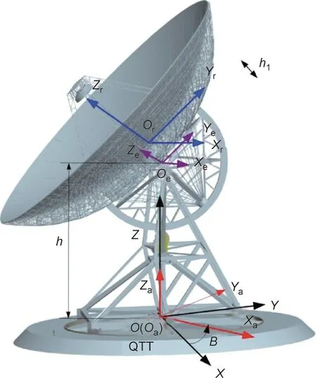
Fig.1. Illustration of the coordinate system of the telescope.B:the azimuth angle of the reflector.
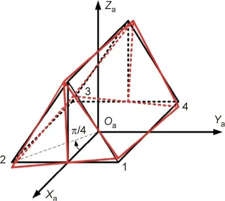
Fig. 2. Inclined deformations in the azimuth frame caused by track error.
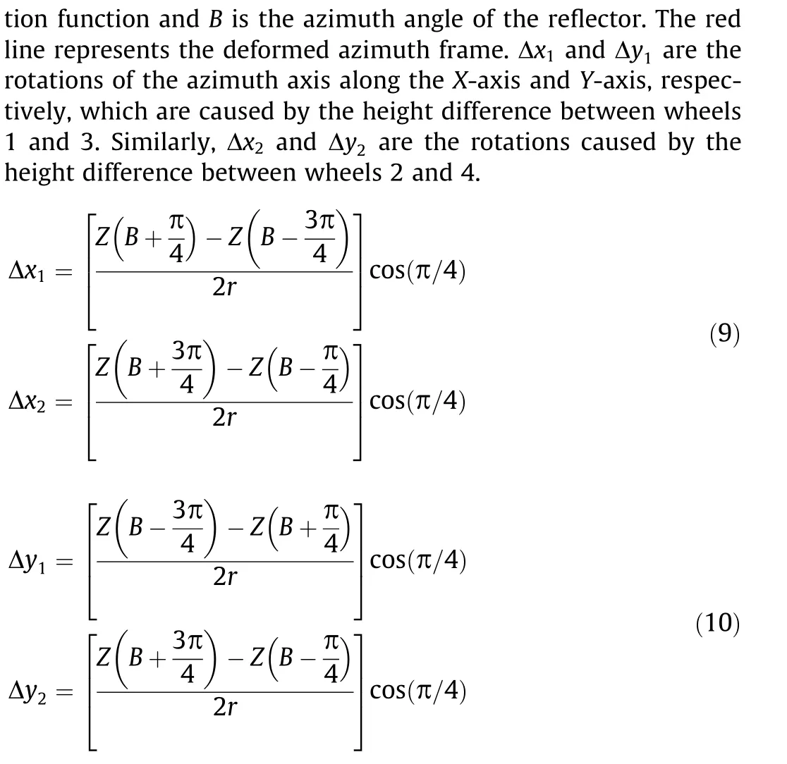
where r is the radius of the track.
In addition,the track error causes a deformation of the azimuth frame; this can cause torsion of the azimuth frame itself, making the elevation axis rotate around the Z-axis, as shown in Fig. 3.The elevation axis translation caused by the height difference between rollers 1 and 2 is δ12,and the displacement caused by rollers 3 and 4 is denoted as δ34.
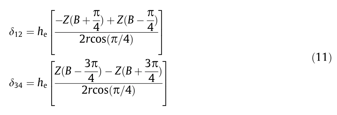
where heis the length of the elevation axis.
The perturbation matrix of the azimuth coordinate system caused by wheel–track unevenness is as follows:
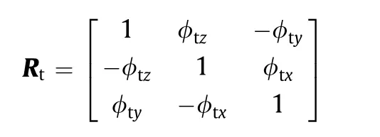
where φtx, φty, and φtzare the errors of the azimuth frame in the coordinate system and can be calculated based on the two-scale model.
The overall inclination of the track can cause inclination of the azimuth axis and there will be an initial offset of zero when the azimuth axis is installed. Considering the track error, the coordinate transformation can be expressed as follows:
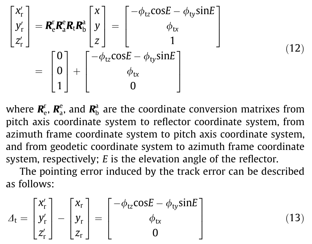
Subsequently,the pointing error in the reflector coordinate system can be converted into the azimuth and elevation error in the geodetic coordinate system. The error of the azimuth is η = Δθr/cosE and the elevation angles error is β = Δφr. θrand φrare the direction and pitch angles in the reflector coordinate system,so Δθrand Δφrare the components of the direction and pitch angle of the pointing error in the reflector coordinate system.
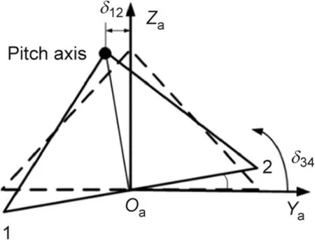
Fig. 3. Distortion of the azimuth frame caused by track error.
3.2. Deduction of the allowable value of track error
Currently, the error distribution of the pointing accuracy of a telescope is a complex engineering problem that requires comprehensive considerations involving multiple factors during the design stage [25]. The distributed pointing errors induced by various error sources can be determined by combining multiple technological means, such as engineering experiences, finite-element structural analysis, control model simulation, measured data, and engineering estimation [26]. Since each error source can affect the pointing accuracy of the telescope, it can be assumed that the pointing errors caused by these error sources can be denoted as Δ1, ..., Δi, ..., Δn. Furthermore, since the distributed pointing errors are scalar and RMS values, the overall pointing error of the antenna ΔPEcan be expressed as follows [27]:

Based on the verification results in Section 2, if the test data of the track error follow a Gaussian distribution, then the relational model between track error and pointing accuracy can be further derived from the perspective of probability statistics. Accordingly,after the RMS of the track error (σ) has been determined,the RMS values of the pointing errors of the azimuth angle and elevation angle of the antenna—which are caused by the track error—can be calculated. Subsequently, the allowable track error values can be derived based on the obtained error distribution. A simplification of the telescope is shown in Fig. 4.
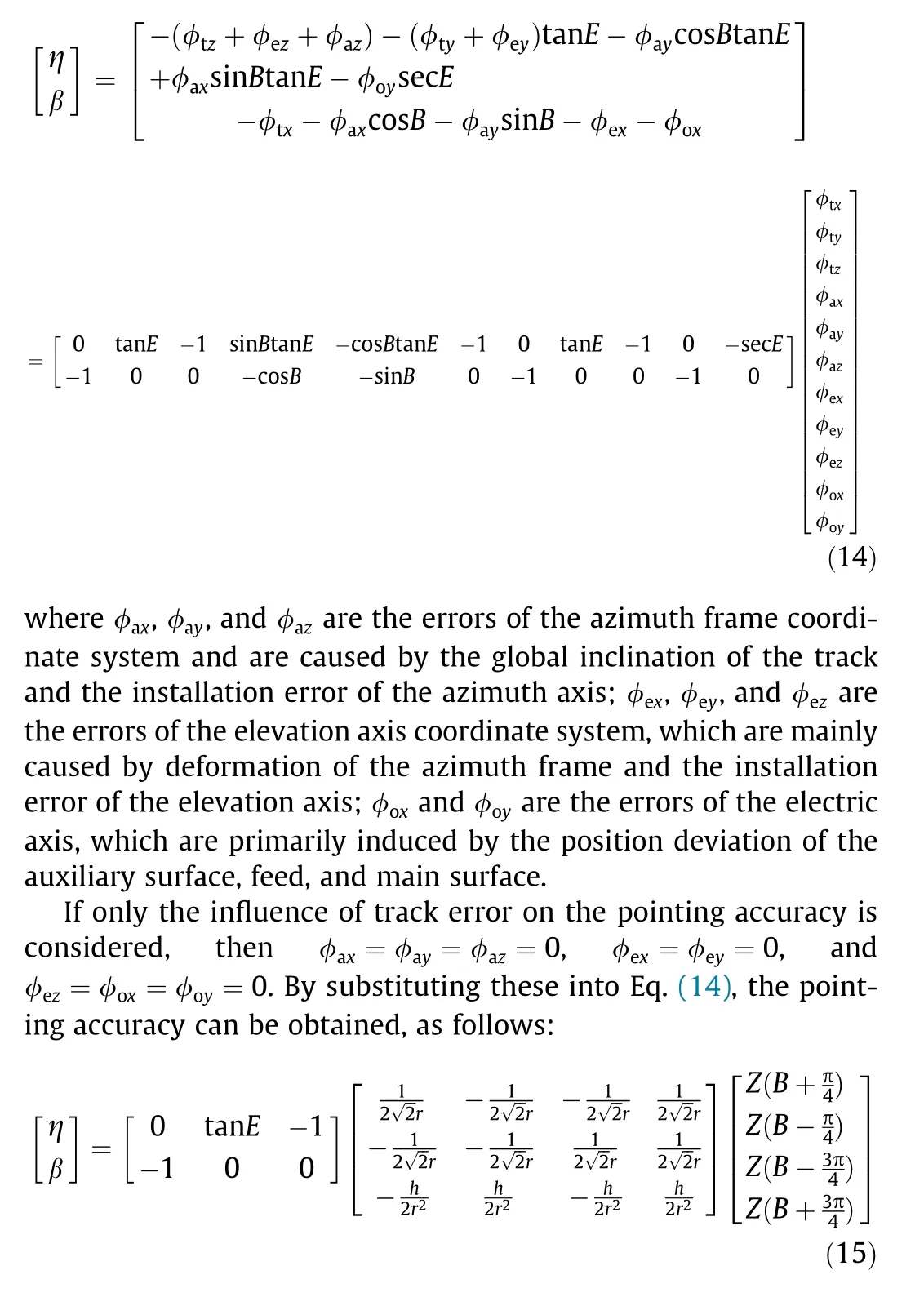
As shown in Fig. 5, four points are used to support the alidade and track of the telescope, which are denoted as points 1, 2, 3,and 4. The bottom structure of the alidade is a square consisting of these four points. If only the track error is considered, then the pointing errors can be described as follows:
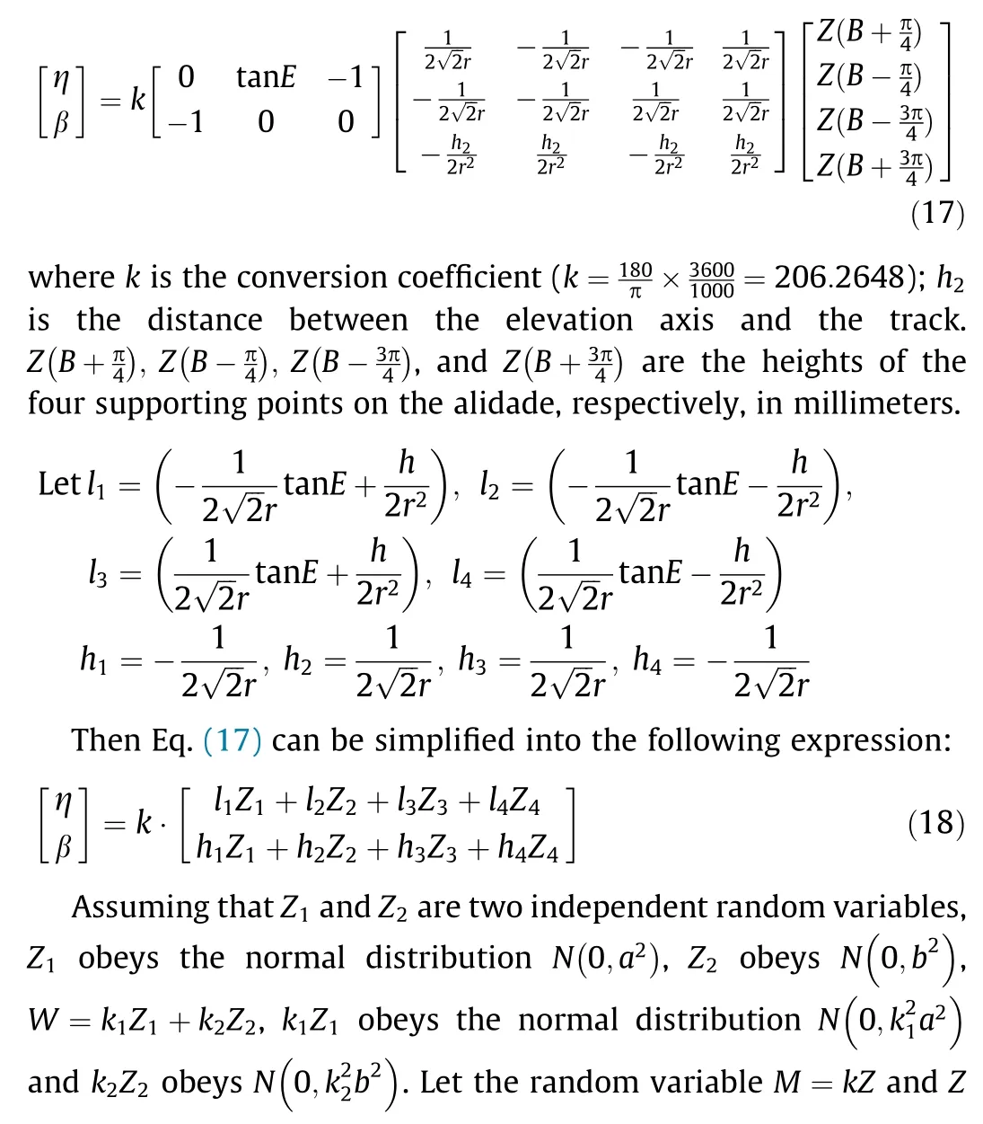
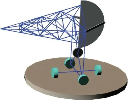
Fig. 4. Simplification of the telescope.
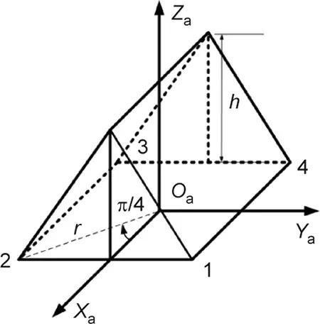
Fig. 5. Position of the supporting points of the alidade and track of the telescope.
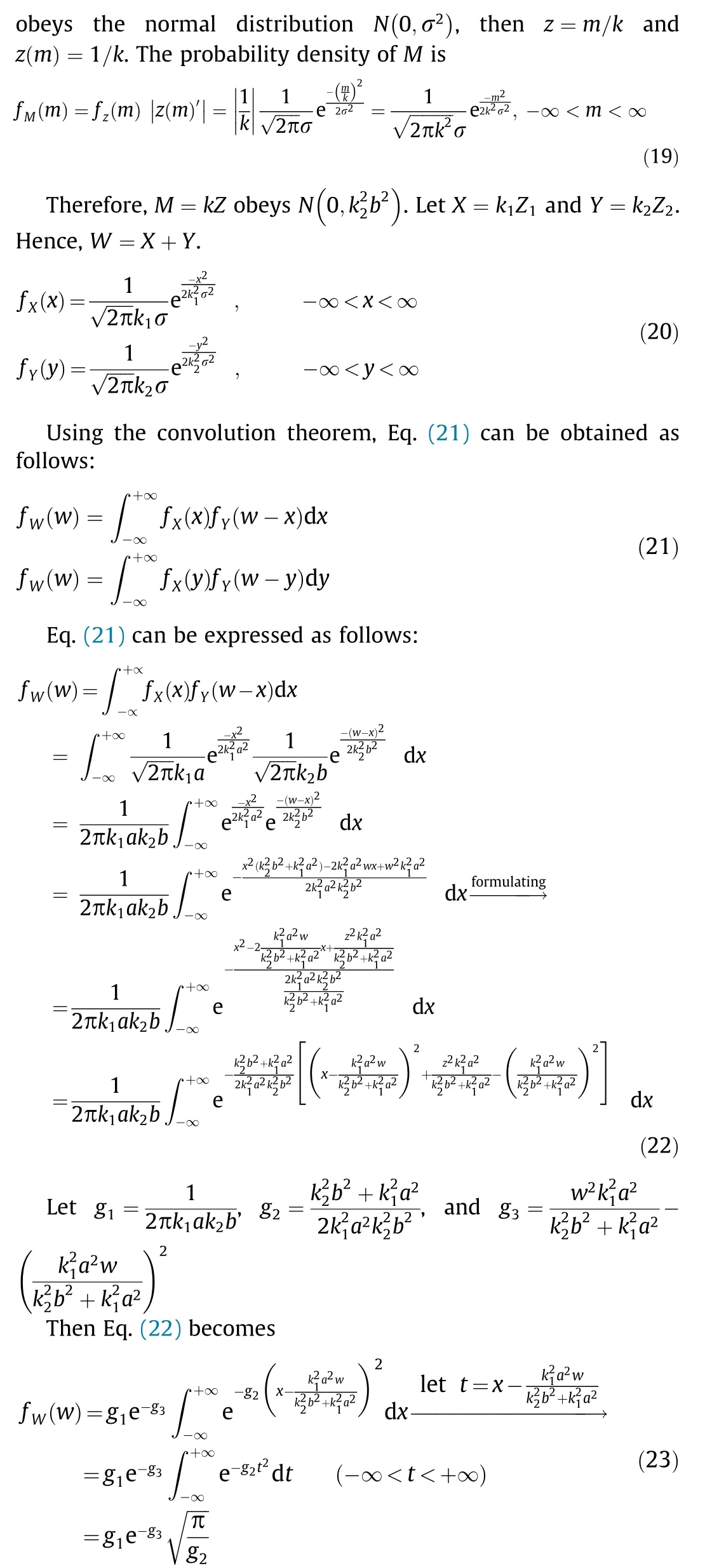
We substitute g1,g2,and g3into Eq.(19)to obtain the following equation:

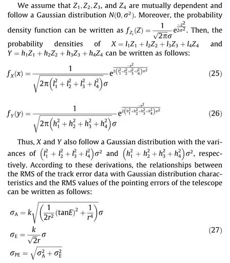
where σA,σE, and σPEare the RMS of the azimuth angle error, the elevation angle error, and antenna’s pointing angle error when the RMS of the track error is equal to σ in arcsec, respectively.
We denote the part of the total pointing error of the telescope that is caused by the track error as θ (RMS). Then, the unevenness requirements for track processing and installation can be reversely derived using Eq. (28), which is the probability statistical model between the track error and pointing error.The detailed derivation process is described as follows:

4. Experimental verification
4.1. Experimental verification for the GBT
The GBT is a radio telescope at the US National Radio Astronomy Observatory(NRAO)in Green Bank,West Virginia,USA,with one of the largest single-dish reflector antennas in the world. At present,the telescope is operated by the Green Bank Observatory. It is 146 m high and weighs 7700 t. The dish antenna is 100 m×110 m in size;after accuracy compensation,the maximum accuracy is 2 arcsec.The GBT is a typical offset radio telescope with a working frequency range of 0.1–116 GHz. The track of the GBT is composed of 48 tracks,with a diameter of 64 m and a total length of 201 m.The RMS of the track error is 0.0568 mm.
The test scheme for the track error is described below[28,29].A plate of known thickness and hardness is placed on the track to calibrate the inclinometer. Subsequently, the alidade was rotated to measure the track.The specific measurement process is as follows.The inclinometer was first installed on the four roller devices at the bottom of the alidade,and a steel disk was placed under the roller.When the roller of the alidade passed, the inclinometer would incline. If the alidade rotated at a constant speed, the relationship between the inclinometer reading and the track error was acquired by ratio enlarging or shrinking of the thickness of the steel disc to the inclinometer reading.Thus,the overall outline of the track was investigated. Using this verification scheme based on the distribution characteristics of the data, a distribution histogram of the track error test data for the GBT was plotted, as shown in Fig. 6.
Analyzed by the correlation coefficient test method, the GBT scale-free interval range is [0.116, 0.901], the fractal dimension is solved by the fractal dimension method based on wavelet transform, and the fractal dimension of GBT is DGBT=1.602, and the track irregularity function is used for modeling,ε1= 2%,ε2= 25%,and ε3=20%,the local description of GBT antenna track irregularity is shown in Fig. 7.
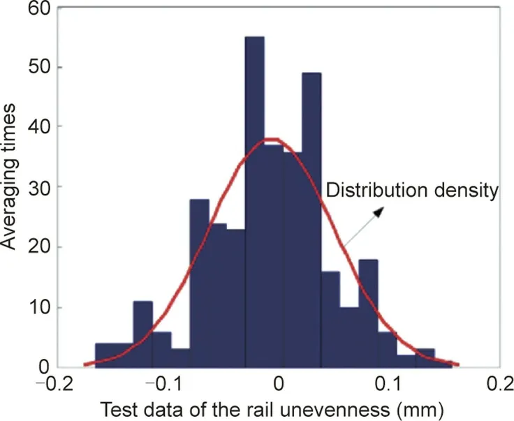
Fig. 6. Distribution histogram of the test data for the track error of the GBT.
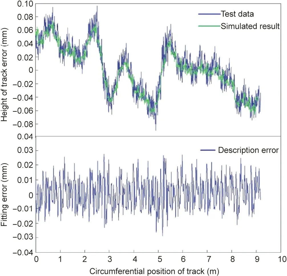
Fig. 7. Comparative study on the track error of the GBT.
To measure the pointing accuracy, a list of radio sources was first determined; then, a cross-scanning observation was made by the telescope.In the observation process,the pointing accuracy and radiant power of the telescope in the associated time were recorded. After the scan observation of the radio point source in the elevation or azimuth direction, a power-change curve with the elevation or azimuth direction was obtained. The presence of the pointing accuracy error resulted in a location deviation of the power maximum and the radio point source.Therefore, the pointing accuracy error of the telescope in the elevation direction was obtained by scanning the radio point source in the elevation direction, and the error in the azimuth direction was obtained by scanning in the azimuth direction.
Taking the GBT as an example and based on the test data, a pointing error model was constructed according to Eq. (17). Then,the corresponding allowable values of track error were reversely derived from the RMS values of the pointing errors, in accordance with Eq. (27). Given the allowable values of track error, the pointing errors were calculated again and compared with the measured value, as listed in Table 1 (E = 45°).
4.2. Experimental verification for the LMT
The LMT, which has an aperture of 50 m and a sub-reflector diameter of 2.5 m, is located in the state of Puebla, Mexico, and is the largest millimeter-wave radio telescope in the world[30,31]. The observation waveband is 0.85–4 mm (75–350 GHz),the surface accuracy is 0.07 mm, and the pointing accuracy is 1 arcsec. The track, which has a diameter of 39.6 m, consists of 20 tracks and has an overall length of 124.4 m. The RMS of the track error is 0.1697 mm.The test scheme used for the LMT was identical to that used for the GBT. Using the verification scheme based on the distribution characteristics of the data, a distribution histogram of the test data for the track error of LMT was also plotted and is presented in Figs. 8 and 9.
Table 2 provides a comparison between the calculated pointing errors of the LMT and the measured values, which shows that the maximum error is 6.5%.
4.3. Experimental verification for Miyun telescope
The Miyun 50 m telescope in Beijing has an aperture of 32.5 m and is composed of 21 tracks,with a total length of 102.1 m and anerror RMS of 0.3136 mm. According to the correlation coefficient test method, the scale-free interval of the Miyun telescope was determined to be [0.263, 1.156], and the fractal dimension of the 50 m antenna was calculated to be D =1.1521 by using the fractal dimension method based on wavelet transform, and the track irregularity function is used for modeling, ε1= 2%, ε2= 25%, and ε3= 20%, the local description of Miyun antenna track irregularity is shown in Fig. 10.

Table 1 Comparisons between the calculated pointing errors and the measured values of the GBT. The caliber of the GBT is 64 m and the RMS of the track is 0.0568 m (E = 45°).
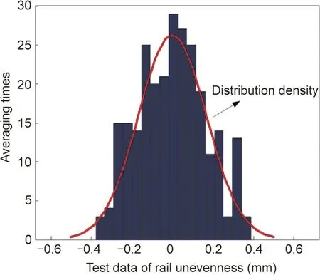
Fig. 8. Distribution histogram of the test data for the track error of the LMT.
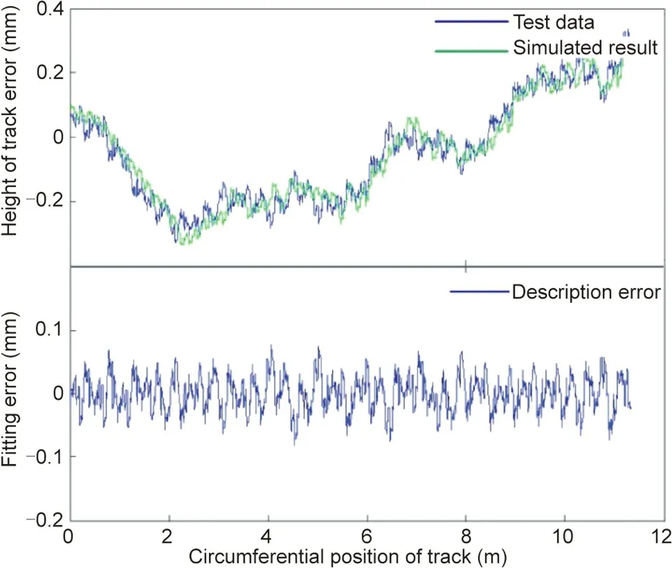
Fig. 9. Comparative study on the track error of the LMT.

Table 2 Comparisons between the calculated pointing errors and the measured values of the LMT. The caliber of the LMT is 39.6 m and the RMS of the track is 0.1679 m.
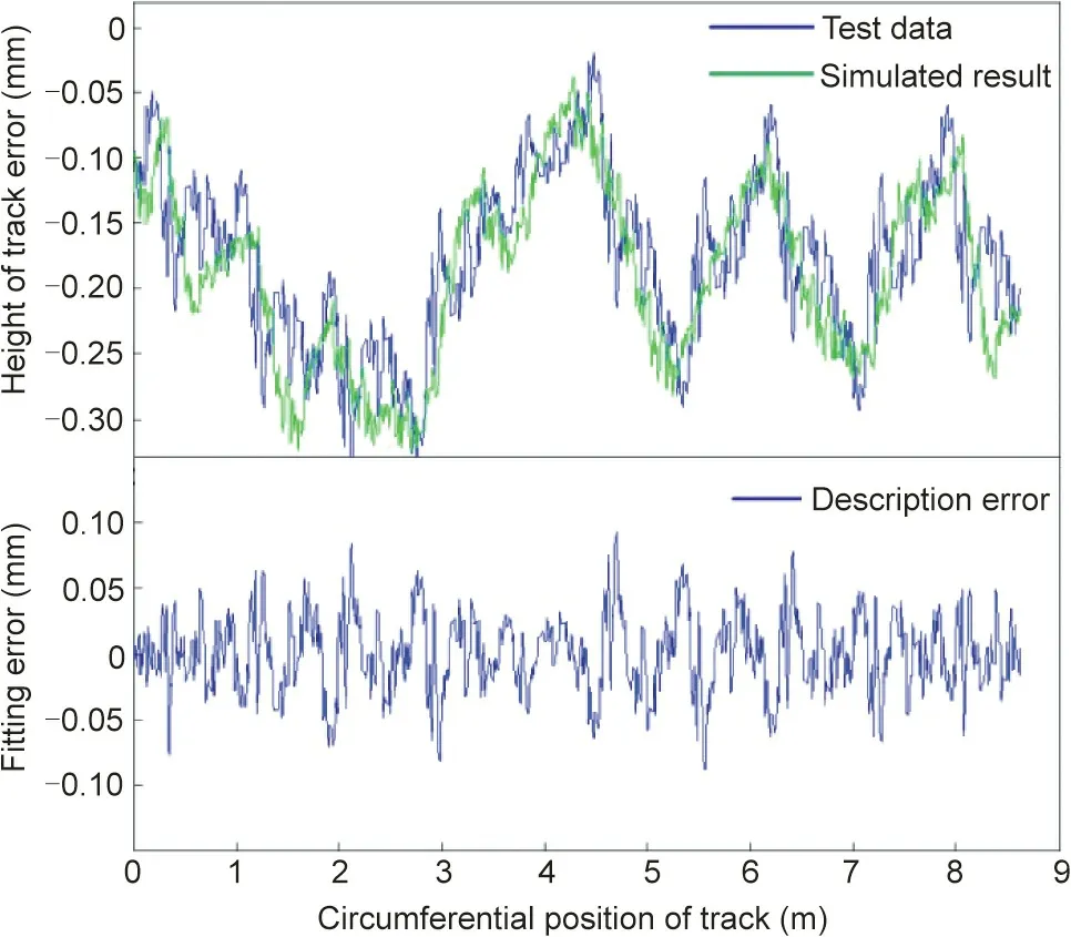
Fig. 10. Comparative study of the track error of the Miyun telescope.
5. Conclusions
A traditional design scheme cannot sufficiently satisfy the extremely high accuracy requirements of large ratio telescopes such as the QTT.To reduce the difficulty of designing and manufacturing the QTT, this study developed a reverse-design method for the track surface. Based on the error characteristics of the track surface, a two-scale description model was proposed to describe the track error. Subsequently, the effect of the track error on the pointing accuracy was established. Finally, using this strategy,the allowable values of track error were reversely derived from the pointing errors induced by track error.An experimental verification of the design method was performed on the GBT and LMT.The results of the comparative analysis of the proposed method and the measured data indicate that the proposed design method is highly effective and feasible.
Acknowledgments
The authors acknowledge financial support from the National Natural Science Foundation of China (51775402 and U1931139).
Compliance with ethics guidelines
Na Li, Baoyan Duan, Xiangyang Li, Bin Zheng, and Jiang Wu declare that they have no conflicts of interest or financial conflicts to disclose.
- Engineering的其它文章
- Electric Air Taxis Create Megadeal Buzz
- Tissue Engineering and Regulatory Science
- Factors Predicting Progression to Severe COVID-19: A Competing Risk Survival Analysis of 1753 Patients in Community Isolation in Wuhan,China
- A Vaccine Based on the Receptor-Binding Domain of the Spike Protein Expressed in Glycoengineered Pichia pastoris Targeting SARS-CoV-2 Stimulates Neutralizing and Protective Antibody Responses
- Fabrication and Applications of Multi-Fluidic Electrospinning Multi-Structure Hollow and Core–Shell Nanofibers
- Past and Future Changes in Climate and Water Resources in the Lancang–Mekong River Basin: Current Understanding and Future Research Directions

