Fabrication and Applications of Multi-Fluidic Electrospinning Multi-Structure Hollow and Core–Shell Nanofibers
Dinming Li, Guihu Yue, Shui Li, Jing Liu, Huike Li, Yun Go, Jinghong Liu, Lnln Hou,Xiofeng Liu, Zhimin Cui, Nü Wng,*, Jie Bi,*, Yong Zho,*
a Key Laboratory of Bioinspired Smart Interfacial Science and Technology of Ministry of Education, School of Chemistry, Beihang University, Beijing 100191, China
b School of Materials Science and Engineering, Lanzhou Jiaotong University, Lanzhou 730070, China
c College of Chemical Engineering, Inner Mongolia University of Technology, Hohhot 010051, China
Keywords:Electrospinning Microfluidics Multi-fluidic Hollow structure Nanofibers
ABSTRACT Recently, electrospinning (ESP) has been widely used as a synthetic technology to prepare nanofibers with unique properties from various raw materials. The applications of functionalized nanofibers have gradually developed into one of the most exciting topics in the field of materials science. In this review,we focus on the preparation of multi-structure fibrous nanomaterials by means of multi-fluidic ESP and review the applications of multi-structure nanofibers in energy,catalysis,and biology.First,the working principle and process of ESP are introduced;then,we demonstrate how the microfluidic concept is combined with the ESP technique to the multi-fluidic ESP technique.Subsequently,the applications of multistructure nanofibers in energy (Li+/Na+ batteries and Li–S batteries), hetero-catalysis, and biology (drug delivery and tissue engineering)are introduced.Finally,challenges and future directions in this emerging field are summarized.
1. Introduction
With the advent of nanotechnology at the end of the 20th century [1], an increasing amount of research has been done on nanofibers and their applications, mainly due to their unique properties such as adjustable chemical composition and engineered high porosity [2–5]. Among the diverse nanofiberproduction methods that have been developed, electrospinning(ESP) is one of the simplest and most effective techniques for fabricating a wide range of one-dimensional (1D) nanomaterials from micron down to nanometer diameters [6–9]. ESP was invented in 1902, but it was not until the 1990s that researchers gradually discovered the great potential of ultrathin fiber materials [10]. It is notable that the number of publications in this area has been increasing rapidly over the past two decades (Fig. 1),due to the aforementioned advantages of this method. So far,ESP has been used to fabricate nanofibers of various materials,such as polymers, metallic compounds, carbon, or composite materials [11–13].
Since Loscertales et al.[14]prepared core–shell materials based on coaxial jets, nanofiber materials with various structures have been reported successively, including hollow structures [15–17],core–shell structures [18], multichannel structures [19], side-byside structures [20,21], lotus-root-like structures [22], and vesicle structures [23]. In comparison with ordinary ESP fibers, multistructure nanofibers exhibit some unique properties.As energy storage materials,conductive multi-structure nanofibers can provide a large amount of space at the micro/nanoscale,which effectively alleviates the volume expansion of the discharge products;there is also the possibility of further optimizing the various properties of nanofiber materials [24]. For catalysis, multi-structure nanofibers are beneficial for improving the spatial distribution of catalysts on the nanofibers, thereby exposing more active sites and providing a favorable catalytic environment[25].In biological contexts,multistructure nanofibers with optimized spatial distribution, surface properties,mechanical properties,and biodegradability have shown great potential in drug delivery and tissue engineering[26].Thus far,multi-structure nanofiber materials have been widely used in energy,catalysis,biology,and many other fields.
The concept of the coaxial ESP method that produces hollow or core–shell nanofibers is very similar to the microemulsion droplets generation concept by the co-flow microfluidic method.In terms of the device used, both methods require a coaxial spinneret that allows the fluid to mix in an orderly manner according to a specific proportion[27–30]; in terms of the fluid,both coaxial ESP and coflow microfluidics require screening and optimization of the fluid’s properties (e.g., surface tension, viscosity, solubility) so that the fluid can meet the requirements of the prepared materials[31,32];and,in terms of products,both methods can prepare materials with a highly homogeneous structure and size [33,34]. In addition,fibers and emulsions with complex structures can be prepared via both methods by adjusting the techniques of ESP and microfluidics(e.g.,device function,fluid parameters,injection rate)[35].In the past two decades,both ESP and microfluidic technology have developed tremendously in the preparation of multistructure materials. Designing a spinneret and introducing more kinds of fluids allow more complex structures to be prepared, as techniques that are useful in one method can be learned from the other method; thus, both methods exhibit broad application prospects [19,27].
In this review, we focus on the fabrication of various multistructure nanofibers via multi-fluidic ESP and discuss their applications in energy,catalysis,and biology.We first briefly introduce the principle of ESP and the influencing factors in the ESP process.We then discuss the preparation of various multi-structure nanofibers—such as hollow, core–shell, multichannel, side-by-side,lotus-root-like, and vesicle nanofibers—by improving the ESP equipment and adjusting the polymer solution. Based on this discussion, we review the advances that have been achieved with multi-structure nanofibers in the fields of energy(Li+/Na+batteries and Li–S batteries),catalysis,and biology(drug delivery and tissue engineering).Finally,we summarize the challenges and opportunities presented by multi-structure materials based on ESP in the future.
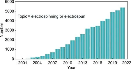
Fig. 1. Paper numbers using the keywords ‘‘electrospinning” and ‘‘electrospun”from 2000 to 2021. These results from Web of Science were available until December 2021.
2. The electrospinning technique
2.1. The principle of electrospinning
ESP is a facile technique to generate 1D fiber or zerodimensional (0D) particle materials [36–40]. The ESP device consists of three components: a spinneret, high-voltage power, and a grounded conductive collector (Fig. 2(a)). The power can provide a voltage of several to tens of kilovolts between the collector and spinneret.The syringe first discharges the viscous polymer solution and/or suitable precursors (e.g., inorganic and carbon precursors)by gravity or a feeding pump. Under a high electric field, the meniscus polymer solution pendant drop is charged and experiences electrostatic forces. When the applied voltage is raised until the surface tension is lower than the electrostatic repulsive force,a conical-shaped jetting fluid (termed the ‘‘Taylor cone”) is formed.In the jetting process, the Taylor cone fluid undergoes a whipping stretch process, which results in solidification of the melt or evaporation of the solvent; finally, solid nanofibers are formed on the collector (Fig. 2(b)) [41]. The jet can also be shrunk into globular individual particles by regulating the properties of the polymer solution, resulting in a large number of micro/nanoparticles (Fig. 2(c)) [19].
In general,many soluble polymers can be used to prepare fibers or micro/nanoparticles by adjusting the ESP parameters.The polymer properties (solubility, molecular weight, etc.), the polymer solution properties (concentration, viscosity, temperature, surface tension conductivity,etc.),the parameters of the ESP process(voltage,feed rate of soluble polymers,distribution of the electric field,type of collector, etc.), and the ambient parameters (humidity,temperature,gas atmosphere,air flow,etc.)play major roles during the preparation of the materials[42].Researchers can adjust these parameters to achieve effective control of the structure(e.g.,cylinder structure, flattened ribbon structure, bead-on-string structure,surface porous structure) and dimensions (nanoscale to microscale) [10,36].
2.2. Multi-structural materials
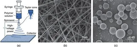
Fig. 2. (a) Conventional ESP equipment with three main parts: a spinneret, high-voltage power, and a grounded conducting collector. Typical ESP products obtained by controlling parameters include(b)fibers(via ESP)and(c)fine particles(via electrospray).(b)Reproduced from Ref.[41]with permission;(c)reproduced from Ref.[19]with permission.
Since Loscertales et al. [14] optimized the combination of various polymer solutions and the design of a coaxial spinneret,a variety of multi-structure materials have been reported in succession.This technology is now used by an increasing number of researchers to prepare multi-structure materials,such as hollow/core–shell nanofibers, multichannel nanofibers, multicavity microcapsules,side-by-side nanofibers,and more.In this review,we mainly focus on the fabrication of fibrous materials by ESP.
2.2.1. Hollow/core–shell nanofibers
Coaxial ESP differs from traditional ESP mainly in terms of the spinneret and polymer solution.The single spinneret used in traditional ESP is replaced by a coaxial spinneret in which two channels are connected to two syringes. The coaxial configuration of the spinneret can provide different pathways for inner and outer solutions. Under a high electric field, inner and outer solutions are charged,and a composite Taylor cone is formed.In the jetting process,the inner and outer solutions undergo a whipping stretch process at the same time,which results in solidification of the melt or evaporation of the solvent; finally, solid nanofibers are formed on the collector. The formation of a composite Taylor cone increases the difficulty of material preparation. When the viscosity of the two fluids is not well matched, a number of issues may ensue: A bead-like structure may form on the fiber skeleton;a small proportion of the shell fluid may fail to contain the core fluid;and two fluids with miscibility may be unable to achieve well-defined core–shell structures. Because the conductivity of the fluid will affect the charge distribution of the Taylor cone, it may not be possible to produce the core–shell structure fiber when the conductivity difference is large. Thus, in comparison with traditional ESP, additional considerations of the miscibility and conductivities between the core and shell solutions are critical for the successful production of hollow/core–shell nanofibers [1,43].
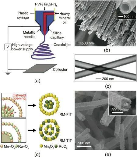
Fig. 3. (a) Schematic illustration of coaxial ESP (PVP: polyvinyl pyrrolidone). (b)Scanning electron microscope (SEM) and (c) transmission electron microscope(TEM) images of the hollow nanofibers. (d) Formation diagram of RuO2/Mn2O3 fiber-in-tube (RM-FIT) and RuO2/Mn2O3 tube-in-tube (RM-TIT). (e) SEM images of RM-FIT. (a–c) Reproduced from Ref. [44] with permission; (d, e) reproduced from Ref. [49] with permission.
As shown in Fig.3(a)[44],the composite spinneret is composed of two coaxial spinnerets. When spinning, heavy mineral oil is ejected from the internal spinneret and an ethanol solution containing polyvinyl pyrrolidone (PVP) and Ti(OiPr)4is ejected from the external spinneret [44]. Uniform hollow nanofibers can be directly fabricated through this approach (Figs. 3(b) and (c)).This technology provides new thinking for the fabrication of hollow/core–shell nanofibers. After the development of the composite spinneret, coaxial ESP has been further developed for more than ten years [43,45,46]. An increasing number of polymer solutions are being developed as the precursors of fibers in order to expand the range of applications [47]. Alternatively, hollow/core–shell nanofibers with complex structures can be prepared by adding templates to the spinning solution to improve the performance in the fields of catalysis or energy [48].
Hollow/core–shell nanofibers can also be prepared by means of traditional ESP followed by heat treatment[12,37].Yoon et al.[49]reported an approach for preparing efficient bifunctional electrocatalysts by utilizing ESP and calcination. As shown in Fig. 3(d)[49], sufficient time and appropriate temperature during the heat treatment caused [Ru–Ox] to preferentially aggregate in the inner region and caused the outer [Ru–Ox] to continuously diffuse into the interior. Finally, RuO2/Mn2O3nanofibers were obtained(Fig. 3(e)). This work opens up a simple way to fabricate various metal oxide hollow nanofibers using ESP technology.
2.2.2. Multichannel nanofibers and multicavity micro/nanoparticles
Multichannel nanofibers and multicavity microcapsules are typical structures prepared by multi-fluidic ESP. Multichannel and multicavity materials have attracted interest due to their unique applications [3,50]. Confronted with the huge challenge of producing multichannel tubular structures and multicavity microcapsule structures on a micro/nanometer scale, Zhao et al.[51] proposed a solution using multi-fluidic ESP. In Fig. 4(a)[51], the preparation of three-channel tubular fibers is demonstrated as an example. The researchers embedded three spinnerets that distributed at the vertices of an equilateral triangle.After the ESP process, fibers were accumulated on the collector.By decomposing the organic components in the fibers through heat treatment, three-channel TiO2tubes were obtained (Fig.4(b)) [51].
The design idea of the spinneret used to obtain multicavity microcapsules is the same as that used for the above multichannel nanofibers (Fig. 4(c))[19]. The viscoelasticity of the spray solution is much lower than that of the spinning solution, such that it is unable to sustain a stable thin liquid thread. As a result, the solution jet breaks up into numerous tiny droplets. The as-prepared particles exhibited spherical morphology,and the two core components were suppressed into individual compartments free of contact (Fig. 4(d)) [19].
Based on this concept, fibers with more channels and microcapsules with more components can be made by designing the configuration of the spinneret. If more channels and core components are necessary, the corresponding number of inner needles are inserted into the outer needle in a certain spatial position, and each needle is fed with core fluid (Figs. 4(e)–(l))[19,51]. This method represents the early use of ESP technology topreparemultichannelnanofibersandmulticavity microcapsules; it provides new thinking on how to prepare materials with complex structures.
2.2.3. Other multi-structure materials
In addition to the aforementioned structures, other typical structures, such as side-by-side structures, vesicle structures, and lotus-root-like structures,can be prepared by regulating the properties of the polymer solution and designing an appropriate spinneret.
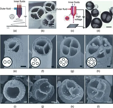
Fig. 4. (a) Schematic diagram of the multi-fluidic ESP process. (b) SEM image of multichannel nanofibers. (c) Schematic diagram of the multi-fluidic electrospray process.(d) TEM image of multicavity microcapsules (scale bar: 1 μm). (e–h) SEM images of fibers with different channel numbers (scale bars: 100 nm). (i–l) SEM images of microcapsules with different cavity numbers, ranging from one to four cavities (scale bar: 500 nm). (a, b, e–h) Reproduced from Ref. [51] with permission;(c, d, i–l) reproduced from Ref. [19] with permission.
Side-by-side nanofibers have recently attracted research attention because they have different exposed surfaces with different components on the two opposite sides [21,52,53]. In 2005,Roh et al. [54] demonstrated the design of polymer particles with two phases. These particles, which were composed of two kinds of polymer, were prepared using a parallel spinneret. Inspired by this work, an increasing number of researchers are improving the ESP equipment to prepare side-by-side nanofibers. Figs. 5(a) and(b) [55] show a confocal laser scanning microscopy (CLSM) image of bicompartmental nanofibers with fluorescein and Nile red fluorescence signals.The CLSM image indicates that both compartments maintained fibrous structures, and distinct interfaces are observed. This side-by-side ESP approach, when applied to different polymer solutions,makes it possible to produce homogeneous biphasic nanofibers by regulating the rheological properties of polymer solutions (including complex viscosity and surface tension).
Vesicle nanofibers prepared by means of emulsion ESP are widely used in drug delivery systems and as electrode materials.Emulsion ESP has the same principles as common ESP, except for an emulsified spinning solution (Fig. 5(c)) [23]. This emulsion is a dispersion system in which a fluid is dispersed into numerous tiny droplets within another continuous immiscible fluid. During the ESP process,the viscosity of the continuous phase increases rapidly with the volatilization of the solvent. Finally, the dispersed-phase droplets deform into a columnar shape under the action of the viscosity shearing gradient, forming fibers with a vesicle structure[56]. Several parameters,including the electric field strength,type of emulsion,surface tension,solution flow rate,and conductivity of the solution, can affect the structure of vesicle fibers; therefore,fibers with wide application prospects can be prepared by controlling these parameters.
Lotus-root-like nanofibers are another typical multi-structure material prepared by means of ESP. In a typical procedure, two incompatible polymer precursors (e.g., the mixture of polystyrene(PS)/polyacrylonitrile (PAN)) are dissolved to form a stable mixed solution in which the two polymers are in a microphase separation state.During the ESP process,the dispersed phase is extruded and stretched into nanoscale wires;next,lotus-root-like nano-channels are generated after selective pyrolysis or a dissolution process, as shown in Fig. 5(d) [57]. The channel structures of the lotus-rootlike nanofibers can be readily changed by controlling the ratio of the dispersed-phase polymers [22].
In conclusion, multi-structure fibrous materials such as hollow fibers,core–shell fibers,multichannel fibers,multicavity microcapsules, side-by-side fibers, vesicle fibers, and lotus-root-like fibers can be controllably prepared by means of the multi-fluidic ESP method.At present,ESP technology is one of the simplest methods to prepare these multi-structure materials and thus expands the scope of application of such materials.
3. Applications of multi-structure fibrous materials
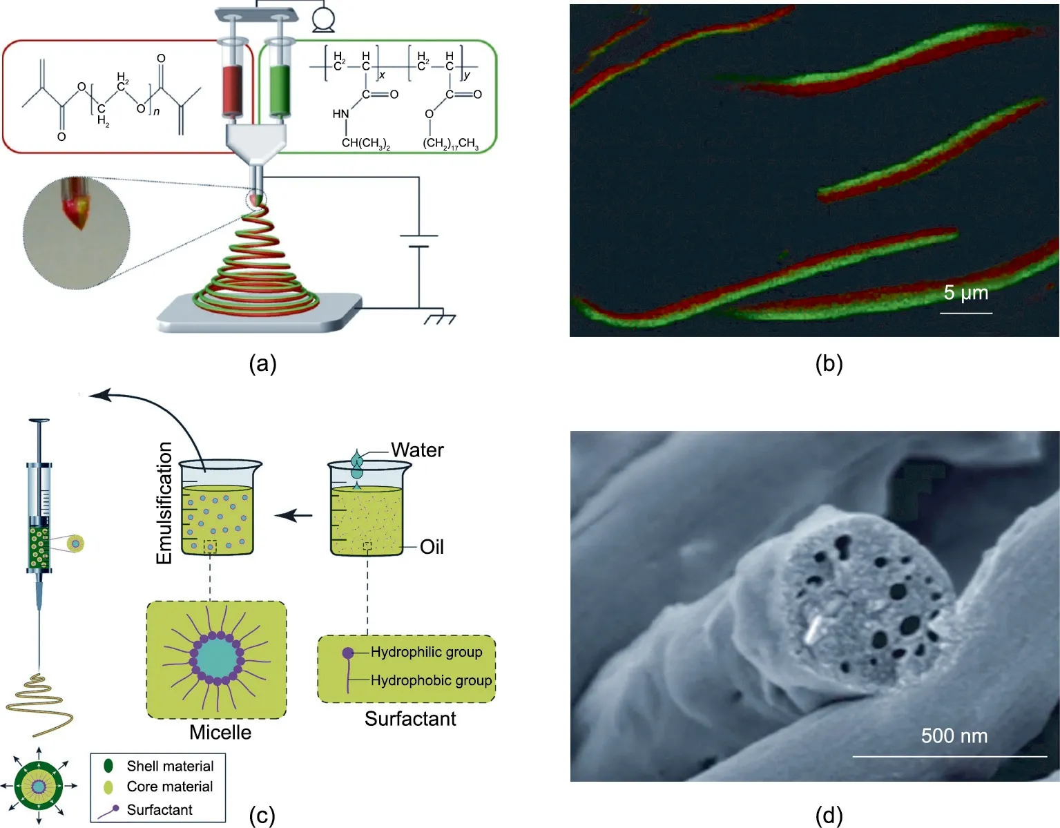
Fig.5. (a)Schematic diagram of a side-by-side ESP process.(b)Confocal laser scanning microscopy(CLSM)image of the side-by-side nanofibers.(c)Schematic diagram of an emulsion ESP process. (d) SEM image of lotus-root-like nanofibers. (a, b) Reproduced from Ref. [55] with permission; (c) reproduced from Ref. [23] with permission;(d) reproduced from Ref. [57] with permission.
Due to their various structures, adjustable chemical composition, and high surface area, multi-structure nanofibers have been used in many fields [58]. Multi-structure nanofibers can provide a large amount of space at the micro/nanoscale to improve the performance of electrode materials.In addition,the many types of nanofiber structures are beneficial for improving the space utilization efficiency in order to increase the contact opportunities between reactants and active sites in catalytic reaction. Moreover,multi-structure nanofibers can easily be designed as materials with porous,controllable degradation and excellent mechanical properties for drug delivery and tissue engineering. To date, many researchers have been devoted to achieving successful applications in the areas of energy, catalysis, and biology [40,59,60].
3.1. Nanofiber application in energy-related applications
As an integral part of functional materials, multi-structure nanofibers with void space offer a large electrode–electrolyte contact area for fast diffusion and accommodate the nonnegligible volume variation in charging/discharging processes.With sulfur hosts,the void space of multi-structure nanofibers is beneficial for the loading of sulfur. These nanofibers have now been demonstrated to have enormous potential for advanced energy storage and conversion technologies, such as Li+/Na+batteries and Li–S batteries.
3.1.1. Li+/Na+batteries
Recently, Li+batteries (LIBs) have been regarded as one of the most useful energy sources for electric vehicles and mobile electric devices [61–67]. Na+batteries (SIBs) have also attracted attention due to their key advantages, which include abundant natural resources and low cost [68]. As electrodes for LIBs/SIBs, active nanomaterials should have facile strain relaxation, a short ion insertion/extraction distance, and an appropriate surfaceto-volume area to come into contact with the electrolyte [4].However, because of their high activity and surface energy, nanomaterials tend to aggregate, which reduces the contact area between the conductive additives and the active materials [10].The multi-structure materials prepared by ESP, such as core–shell nanofibers, hollow nanofibers, vesicle nanofibers, and lotus-rootlike nanofibers, ensure effective contact even if there is a small amount of self-aggregation. Therefore, multi-structure nanofibers are one of the most favorable electrode materials [69–75].
Hwang et al. [76] developed an ESP process to prepare core–shell nanofiber electrodes (Fig. 6(a)). Commercial silicon (Si)nanoparticles were wrapped in the core by a carbon shell, as shown in Fig.6(b).The unique core–shell structure alleviated many of the problems of a Si anode during charge and discharge,such as unstable contact between the Si nanoparticles and the conductive carbon, and the vulnerability of the solid-electrolyte interphase.The Si nanoparticles at C nanofibers exhibited excellent performance, with a gravimetric capacity as high as 1384 mA∙h∙g-1, a 5 min discharging rate capability while retaining 721 mA∙h∙g-1,and a cycle life of 100 cycles with almost no capacity loss (Fig. 6(c)) [76]. The ESP core–shell nanofiber provides a new way of design that addresses the volume expansion of LIB electrodes.
Li et al.[77]prepared CaSnO3nanotubes(CSO-NTs)by means of a facile ESP method followed by calcination(Figs.6(d)and(e)).The scanning electron microscope (SEM) image in Fig. 6(e) clearly shows that the CSO-NT has a hollow structure with rough inside and outside surfaces. When used as anode materials, CSO-NTs exhibited good cyclic stability. Wang et al. [56] fabricated highly Na-accessible TiO2–C microfibers (NTMFs-C) via emulsion ESP;the NTMFs-C delivered an enhanced capacity of 167 mA∙h∙g-1after 450 cycles at a current density of 50 mA∙g-1, while retaining a capacity of 71 mA∙h∙g-1at the high current rate of 1 A∙g-1(Figs.6(g)–(i)). Because of their thin TiO2inner walls and porous structure,the NTMFs-C exhibit fast Na+transport,high ion accessibility,and easy electron transport.
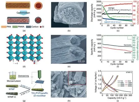
Fig. 6. (a) Schematic diagram of Si nanoparticles (SiNP) at C nanofiber carbonization steps (PMMA: poly(methyl methacrylate)). (b) SEM image of the SiNP at C core–shell nanofibers.(c)Cycling performance of SiNP at C core–shell nanofibers measured at a C/5 rate.(d)Crystal structure of CaSnO3 nanotubes(CSO-NTs).(e)SEM image of CSO-NTs.(f)Cycling performance of CSO-NTs.(g)Schematic diagram of the synthetic processes for TiO2 and TiO2–C fibers via the ESP technique.(h)SEM images of TiO2–C microfibers.(i) Charge/discharge curves of TiO2–C fibers. (a–c) Reproduced from Ref. [76] with permission; (d–f) reproduced from Ref. [77] with permission; (g–i) reproduced from Ref.[56] with permission.
Recently,Gao et al.[12]fabricated Sn/SnO2at carbon nanofibers by means of ESP and an annealing method. These nanofibers provided effective contact between the electrolyte and electrode materials due to their special structure,which possesses abundant inner spaces and a larger specific surface area. After 2000 cycles,the electrode materials exhibited a high specific capacity of 986 mA∙h∙g-1. This excellent electrochemical performance indicates that Sn/SnO2at carbon hollow nanofibers have promising applications in high-performance LIBs.
3.1.2. Li–S batteries
Li–S batteries have attracted a great deal of attention because their theoretical specific energy is much higher than that of commercial LIBs [78–81]. Li–S batteries have thus become a powerful contender for future energy storage devices in electric vehicles and portable electronics[38].However,the serious‘‘shuttle effect”and the severe lithium dendrites are the main adverse factors hindering the development of Li–S batteries [24,82,83]. ESP nanofibers, due to their superior structures, exhibit unique properties that could solve the aforementioned problems.
Recently, researchers have explored the application of multistructure nanofibers in Li–S batteries. Wu et al. [84] fabricated meso-hollow and microporous carbon nanofibers (MhMpCFs) via coaxial ESP followed by carbonization. As shown in Figs. 7(a) and(b) [84], the MhMpCFs were thermal treated with sulfur powder to form a S/MhMpCFs composite,which was used as the electrode material in Li–S batteries.The micropores effectively encapsulated the sulfur (S) active material and alleviated the dissolution of soluble polysulfides in the electrolyte, while the mesopores provided channels for rapid diffusion of lithium ions.Electrochemical studies showed that the maximum capacity of the S/MhMpCFs electrode material was 815 mA∙h∙g-1,and its capacity was maintained at 715 mA∙h∙g-1after 70 cycles (Fig. 7(c)),corresponding to a retention of 88%. This work and other earlier studies [85,86] have inspired the application of multi-structure materials prepared by ESP in the field of lithium batteries.
Li et al.[22]successfully fabricated three-dimensional(3D)networks of lotus-root-like multichannel carbon (LRC) nanofibers via ESP (Figs. 7(d) and (e)). Through a simple dip-and-dry method,the LRC loaded with S powder was tightly wrapped by an ethylenediamine-functionalized reduced graphene oxide (EFG)layer; the resulting material was termed LRC/S@EFG. The LRC/S@EFG effectively enhanced the cycling stability of the electrode. The capacity was also increased to more than 8 mA∙h∙cm-2(Fig. 7(f)). Thus, these ESP nanofibers are having a positive impact on the development of high-performance batteries.
In addition to the aforementioned carbon fibers, transitionmetal compound fibers can be prepared by ESP and fiber posttreatment technology for application in the energy field. Liao et al. [87] designed root-like TiN/C nanofibers for Li–S batteries as a freestanding host (Figs. 7(g) and (h)). These TiN/C nanofibers demonstrated excellent high-sulfur utilization and rate capability.For TiN/C materials with 4.0 mg∙cm-2S loading, a high stable capacity of 983 mA∙h∙g-1was maintained at 0.2C (Fig. 7(i)). This performance improvement benefited from the multi-structure TiN/C nanofibers: ① The abundant vesicles in the root-like nanofibers provided space to relieve the volume expansion; and②the TiN anchored the polysulfides and boosted the electrochemistry reaction.The use of this unique structure is expected to result in high performance and high S-containing cathodes, which are favorable for the practical application of Li–S battery technology.
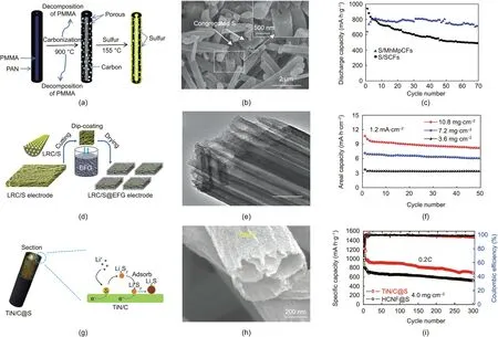
Fig. 7. (a) Schematic diagram of the synthesis processes of the S/MhMpCFs composite. (b) SEM image of the S/MhMpCFs composite. (c) Cycling performance of the S/MhMpCFs composite(SCF:solid carbon nanofiber).(d)Synthesis process of LRC nanofibers loaded with sulfur and coated ethylenediamine-functionalized reduced graphene oxide (EFG) (LRC/S@EFG). (e) TEM image of LRC (scale bar: 200 nm). (f) Areal capacities of LRC/S@EFG electrodes during cycling. (g) Schematic diagram of the electrode process for the TiN/C at S cathode. (h) SEM image of TiN/C nanofibers. (i) Cycle life and Coulombic efficiency of TiN/C at S electrodes with 4.0 mg∙cm-2 S loading (HCNF:hollow carbon nanofiber). (a–c) Reproduced from Ref. [84] with permission; (d–f) reproduced from Ref. [22] with permission; (g–i) reproduced from Ref. [87] with permission.
3.2. Nanofiber application in catalysis
Compared with routine bulk materials, ESP nanofibers possess greater specific areas, more active sites, and a more active lattice plane, which endow them with great potential in catalysis[25,88].In particular,multi-structure nanofiber materials with hollow,core–shell,or multichannel structures have broad prospects in the field of catalysis [89].
Wang et al. [90] developed a novel methodology to fabricate TiO2–SiO2nanofibers with a tunable porous structure by means of single-spinneret ESP (Fig. 8(a)). The mesoporous composite nanofibers of TiO2–SiO2containing an appropriate ratio of anatase/rutile exhibited excellent photocatalytic activity in the degradation of rhodamine B(RhB).Under light,TS-8.08(TS-n,where n is the Ti/Si molar ratio) degraded around 94% of the RhB in 20 min,and the degradation of RhB was complete in 50 min (Fig. 8(b)).The degradation rate constants of RhB by means of TS-8.08 and Degussa P25 were 0.1071 and 0.0895 per minute respectively,showing that TS-8.08 degrades RhB faster than Degussa P25(Fig. 8(c)). The combination of high RhB adsorption and the high specific surface area of TS-8.08 allowed the RhB easy accessibility to the active sites,resulting in excellent photodegradation activity.This work opens up a new direction toward the advanced application of rationally designed hetero-structure inorganic fibers and tunable interconnected porous hierarchical structures.
Functionalized hollow structured fibers also have unique advantages in catalysis. Kang and Hwang [91] successfully fabricated hollow activated carbon nanofibers (HACNFs) embedded with Mn3O4nanoparticles (Mn3O4/HACNFs) (Fig. 8(d)). Because of the hollow structure, the adsorption capacity of the Mn3O4/HACNFs to toluene was very strong. Compared with traditional activated carbon nanofibers, the adsorption breakthrough time of toluene was longer, as shown in Figs. 8(e) and (f). These results indicate that Mn3O4/HACNFs have potential for capturing volatile organic compounds.
Materials with a hierarchical porous structure have been applied in some fields because of their ready mass transfer properties[92,93].In fibrous materials,due to the large ratio of length to diameter,the inner surfaces of hollow fibers cannot be used effectively. Yue et al. [94] developed hollow through-hole TiO2nanofibers with gold (Au) nanoparticles (Au/TiO2HTHNFs) via a coaxial ESP method (Fig. 8(g)). The Au/TiO2HTHNFs exhibited high catalytic activity (Fig. 8(h)) and cyclical stability (Fig. 8(i)) in a liquid-phase 4-nitrophenol reduction reaction. The through-holes on the nanofibers provided enough mass transfer channels for the reactants to enter the inner space, which permitted the exchange of reactants and products between the inner space and the outside space. The active molecules were quickly refreshed,which increased the reaction rate.Therefore,the reaction rate was significantly increased by mass transfer enhancement. This strategy of mass transfer enhancement can easily be extended to many hollow nanomaterials, with promising applications in the catalyst and energy fields.
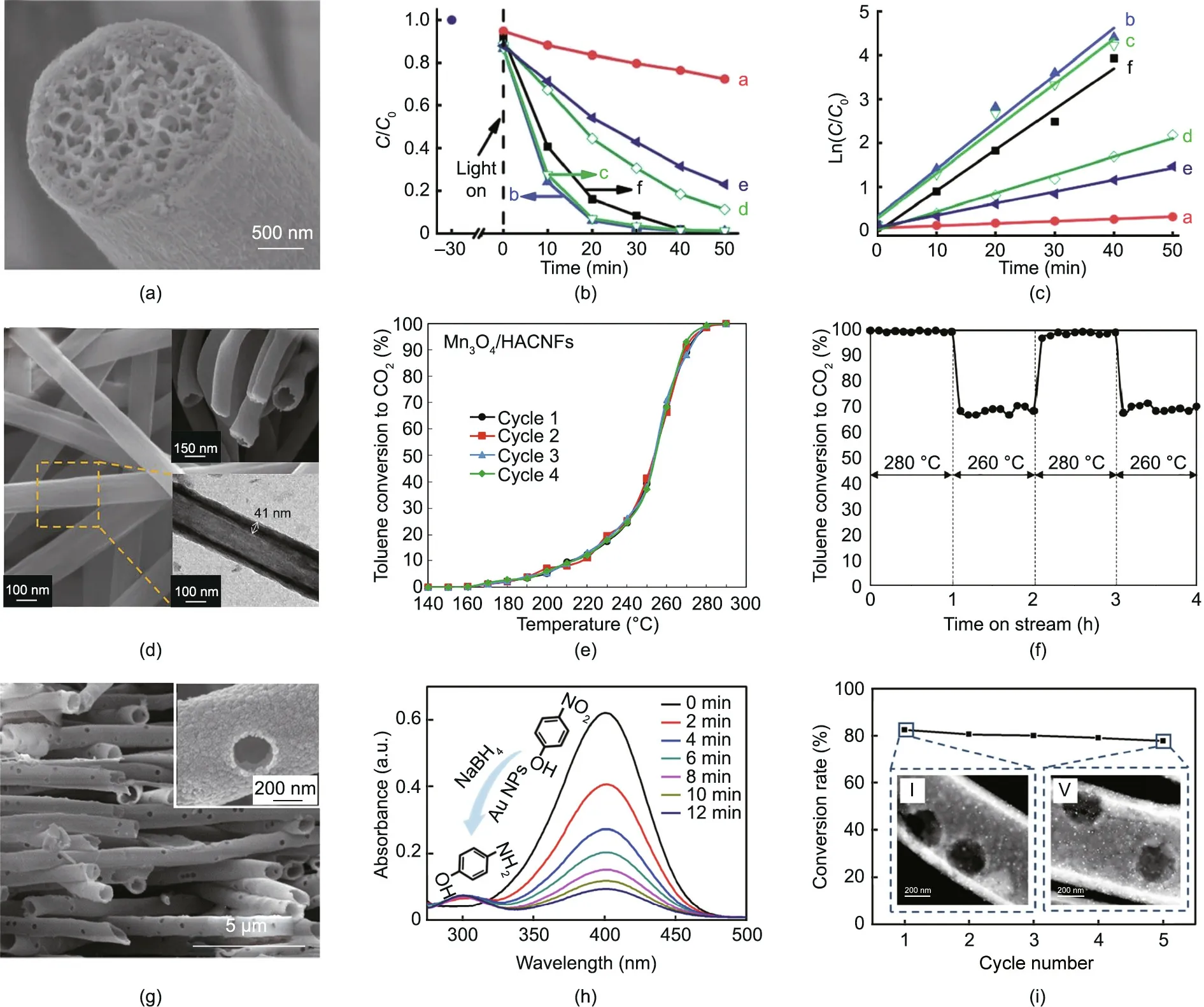
Fig. 8. (a–c) TiO2–SiO2 composite nanofibers for photocatalysis: (a) SEM image of porous TiO2–SiO2 composite nanofibers; (b) photocatalytic degradation of rhodamine B(RhB)monitored at normalized concentration change(C/C0)vs irradiation time(t)(a:TS-N;b:TS-8.08;c:TS-5.41;d:TS-2.53;e:TS-1.18;f:P25);(c)reaction rate constants associated with RhB photodegradation (a: TS-N; b: TS-8.08; c: TS-5.41; d: TS-2.53; e: TS-1.18; f: P25). (d–f) Mn3O4 nanoparticles embedded in hollow activated carbon nanofibers (Mn3O4/HACNFs) for toluene removal: (d) SEM and TEM images of hollow nanofibers; (e) reusability tests of Mn3O4/HACNFs for the total oxidation of toluene;(f) evolution of conversion to CO2 with the time on stream of Mn3O4/HACNFs. (g–i) Au/TiO2 hollow through-hole nanofibers (Au/TiO2 HTHNFs) for photocatalysis: (g) SEM images of TiO2 HTHNFs;(h)ultraviolet/visible(UV/vis)absorption spectrum of the reaction solution with different reaction times(a.u.:arbitrary unit);(i)catalytic activity of Au/TiO2 HTHNFs in reduction showing a negligible decrease in five cycles.(a–c)Reproduced from Ref.[90]with permission;(d–f)reproduced from Ref.[91]with permission;(g–i) reproduced from Ref. [94] with permission.
3.3. Nanofiber application in biology
ESP fiber systems are widely used in various fields due to their diverse structure and adjustable porosity [2,95–98]. The excellent intrinsic properties of nanofibers, which include structural diversity and high porosity, are beneficial for the loading and release of various drugs [58]. ESP nanofibers can mimic the extracellular matrix (ECM) and are used in tissue engineering as promising two-dimensional (2D) or 3D scaffolds.
3.3.1. Drug delivery
Because of their diverse structures, ESP nanofibers have adjustable surface properties; they can also be similar to the ECM[99]. These properties give nanofibers the following advantages in drug delivery: ① The diversity of polymer species can be adapted to many reagents with different physicochemical properties [100]; and ②the unique physicochemical properties of polymers enable high drug loading and high encapsulation efficiency[58]. These advantages of ESP fibers have laid a solid foundation for their future development, making it possible to develop commercial products based on ESP.
Due to their ability to carry drugs, nanocarriers have attracted wide attention in cancer therapy, although their applications are still limited due to their low delivery efficiency of intravenous chemotherapy drugs. Yang et al. [101] developed a local drugdelivery device combining implantable polymeric nanofibers and an active targeting micellar system (Fig. 9(a)). This design was achieved by hydrophobic doxorubicin (DOX)-encapsulated active targeted micelles. The core/shell nanofibers, which had poly(vinyl alcohol) (PVA) and the micelles as the core region and gelatin as the outer region, were prepared by coaxial ESP, as shown in Fig. 9(b). The implantable device, when equipped with agents of low-dose therapy, can ensure long-term drug concentrations at tumor sites while maintaining low systemic drug exposure to normal tissues, compared with the usual delivery strategies for repeated intravenous micelle therapy. Moreover, these micelles can be further internalized into tumor cells through receptormediated endocytosis, thus producing higher therapeutic effects on tumor cells and lower toxicity to normal tissues (Fig. 9(c)). In addition,this implantable device can greatly reduce the frequency of dosing and has the potential to improve the life quality and compliance of patients.The study opens up new possibilities for developing implantable devices for safe cancer treatment.
Due to the quick degradation of mycophenolic acid (MPA), the development of an anti-tumor therapy based on MPA has been hampered. To resolve this problem, Han et al. [102] prepared MPA-containing ESP coaxial fibers as a local drug-delivery vehicle(Fig.9(d)).These fibers,which had poly(ε-caprolactone)(PCL)-MPA or PVP-MPA as the core region and PCL as the outer layer,provided an excellent slow released effect in comparison with common fibers (Fig. 9(e)). A thicker PCL shell provided gradual release in the initial period and higher MPA release after the media had been refreshed.The structure of the fibers had a significant effect on the release of MPA, with coaxial fibers with a PVP-MPA core and PCL sheath exhibiting better sustained release than PCL-MPA and PVP-MPA fibers,as shown in Figs.9(f)and(g).This study indicates that MPA-containing ESP fibers have great potential for the local treatment of glioblastoma multiforme.
3.3.2. Tissue engineering
In recent years,ESP fibers have been widely used in tissue engineering due to their similar structure to the natural fiber structures of the ECM [105]. Xu et al. [103] prepared a bicomponent scaffold with island-like core–shell fibers that combined the respective advantages of chitosan (CS) and polylactic acid (PLA) via ESP(Figs. 10(a) and (b)). The results of implanting preosteoblast(MC3T3-E1)cells on the modified scaffold showed that the CS components and rough surface structure balanced the hydrophilicity and hydrophobicity of the fiber and provided convenient conditions for cell attachment and growth. The ‘‘island-like” structure and CS on the coaxial nanofiber surface increased the cell activity and provided more appropriate conditions for cell proliferation(Figs. 10(b) and (c)). This research provides a new way for the design of PLA scaffolds, which can be applied in biomedicine to the surface between materials and cells, combining topography and bioactive modification effects.
The presence of osteoconductive and osteoinductive factors plays an important role in promoting the differentiation of stem cells into osteogenic lines. Shalumon et al. [104] prepared silk fibroin (SF)/CS/nanohydroxyapatite (nHAP)/bone morphogenetic protein-2 (BMP-2) (SCHB2) nanofiber membrane (NFM) with BMP-2 as the core and SF/CS/nHAP as the shell of nanofibers(Figs.10(e) and (f)). The BMP-2 released from the nanofibers exhibited bone-induced activity in human-bone-marrow-derived mesenchymal stem cells(hMSCs).The incorporation of the BMP-2 promoted the osteogenic differentiation of hMSCs; thus, the SCHB2-thin NFMs, in comparison with SF/CS and SF/CS/nHAP NFMs, were shown to be the best scaffold material for cell culture in vitro(Fig. 10(g)) [104]. Hence, SCHB2-thin NFMs may be considered as a potential material for bone-specific tissue regeneration.
4. Summary
In summary, multi-fluidic ESP technology is a very simple and general method for preparing multi-structure nanofibers with different functions. Given the advantages of fiber materials and the demand for novel functional materials, multi-structure nanofibers show great potential in many areas, including energy (LIBs, SIBs,and Li–S batteries),catalysis,and biology(drug delivery and tissue engineering), which were highlighted in this review.
5. Challenges and outlook
ESP technology has become an important method for preparing nanofibers.However,some problems remain to be addressed prior to widespread nanofiber application.
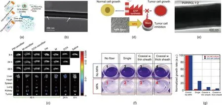
Fig. 9. (a–c) Core/shell poly(ethylene glycol) (PEG)/poly(ε-caprolactone) (PCL) nanofibers for drug release: (a) schematic diagram of the drug release (FA: folic acid;DOX: doxorubicin; FM: DOX-loaded FA-decorated micelle); (b) TEM image of micelle-encapsulated PEG/PCL nanofiber; (c) in vivo and ex vivo DOX fluorescence images(M:micelle).The fibers of the core–shell structure ensure that there are therapeutic drug levels at the tumor site.(d–g)Core/shell(PVP-MPA)/PCL nanofibers for drug release:(d) schematic diagram of the effect of MPA on brain tumor cells (GTP: guanosine-5′-triphosphate); (e) TEM observation of PVP/PCL coaxial fiber; (f) photos of glioblastoma multiforme cell cultures exposed to MPA-containing fiber membranes and control samples after one week(w.:with);(g)relative growth rate of tumor cell cultures exposed to different materials. (a–c) Reproduced from Ref. [101] with permission; (d–g) reproduced from Ref. [102] with permission.
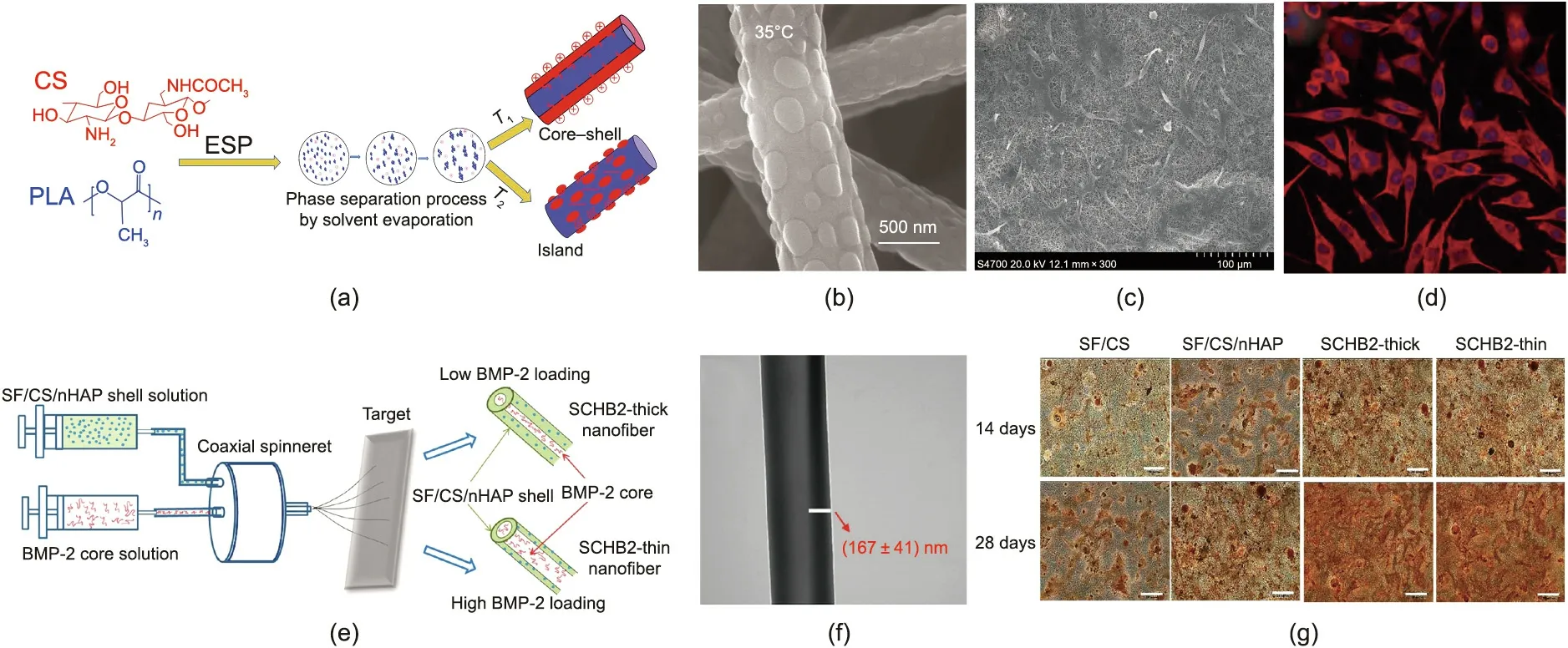
Fig. 10. (a) The preparation process of chitosan (CS) islanded structured scaffolds. (b) SEM images of ESP polylactic acid (PLA)/CS nanofibers. (c) SEM and (d) laser confocal scanning microscope micrographs of cells grown and attached for 48 h. (e) Schematic diagram of the preparation of silk fibroin (SF)/CS/nanohydroxyapatite (nHAP)/bone morphogenetic protein-2 (BMP-2) (SCHB2) nanofibrous membranes (NFMs) through coaxial ESP. (f) TEM image of SCHB2-thick. (g) Von Kossa staining of the mineral deposition of human bone-marrow-derived mesenchymal stem cells(hMSCs)cultured on different NFMs for 14 and 28 days(scale bar:200 μm).(a–d)Reproduced from Ref.[103] with permission; (e–g) reproduced from Ref. [104] with permission.
(1) Mass production. Low productivity is the main disadvantage in the commercial application of ESP nanofiber materials—especially multi-structure nanofiber materials. Thus far, many pieces of ESP equipment have been developed for the large-scale production of nanofibers.Although these approaches can fabricate simple solid nanofiber materials, they are still unsuitable for the preparation of multifunctional, multi-structure nanofiber materials.
(2)Multi-structural controllability.Many factors,such as temperature, humidity, the feed rate of soluble polymers, and so on,affect the preparation of ESP materials. In particular, when more complex multi-fluidic ESP is involved, the spinnability of multiple polymers and the yield of multi-structure fibers are greatly impacted. Therefore, one direction for future efforts should be to optimize the spinning conditions and design more reliable equipment.
(3) Practicability of multi-structure nanofibers. Although multi-structure nanofibers have been used in many fields, their irreplaceable applications remain vague.
(4)Lack of clarity on mechanisms.For a multi-fluid and complex ESP system, the specific response process of the multipolymer solution and the electric field remains unclear.
Although many technical problems and parameters remain to be improved, there is no doubt that multi-fluidic ESP has the potential to be one of the most powerful technologies for the preparation of materials with multifunctional properties. ESP materials will also play an increasingly important role in production,providing exciting opportunities for development in the fields of energy,the environment,catalysis,biology,photonics,and electronics. Optimizing the structure and composition of nanofibers will open up new fields for the preparation of various functional materials in the future.
Acknowledgments
The authors acknowledge the National Natural Science Foundation of China (22175007, 21975007, 21774005, and 21433012),the National Natural Science Foundation for Outstanding Youth Foundation,the Fundamental Research Funds for the Central Universities,the National Program for Support of Top-Notch Young Professionals, the 111 project (B14009), the National Postdoctoral Program for Innovative Talents (BX20190027), and the China Postdoctoral Science Foundation Funded Project(2019M650431).
Compliance with ethics guidelines
Dianming Li,Guichu Yue,Shuai Li,Jing Liu,Huaike Li,Yuan Gao,Jingchong Liu, Lanlan Hou, Xiaofeng Liu, Zhimin Cui, Nü Wang, Jie Bai,and Yong Zhao declare that they have no conflict of interest or financial conflicts to disclose.
- Engineering的其它文章
- Electric Air Taxis Create Megadeal Buzz
- Tissue Engineering and Regulatory Science
- Factors Predicting Progression to Severe COVID-19: A Competing Risk Survival Analysis of 1753 Patients in Community Isolation in Wuhan,China
- A Vaccine Based on the Receptor-Binding Domain of the Spike Protein Expressed in Glycoengineered Pichia pastoris Targeting SARS-CoV-2 Stimulates Neutralizing and Protective Antibody Responses
- Past and Future Changes in Climate and Water Resources in the Lancang–Mekong River Basin: Current Understanding and Future Research Directions
- Mass Transfer,Gas Holdup,and Kinetic Models of Batch and Continuous Fermentation in a Novel Rectangular Dynamic Membrane Airlift Bioreactor

