Reflection and transmission of an Airy beam in a dielectric slab
Xiaojin Yang(杨小锦), Tan Qu(屈檀), Zhensen Wu(吴振森), Haiying Li(李海英),Lu Bai(白璐), Lei Gong(巩蕾), and Zhengjun Li(李正军)
1School of Physics and Optoelectronic Engineering,Xidian University,Xi’an 710071,China
2School of Electronic Engineering,Xidian University,Xi’an 710071,China
3School of Photoelectric Engineering,Xi’an Technological University,Xi’an 710021,China
Keywords: Airy beam,dielectric slab,Fresnel approximation,reflection and transmission
1. Introduction
The Airy beam was firstly predicted by Berry and Balazs as a solution to potential-free Schr¨odinger’s equation in quantum mechanics.[1]It was not until 2007 that the finite energy Airy beam was realized theoretically and experimentally by Siviloglou and Christodoulides.[2,3]Recently, nondiffracting[4]and self-accelerating[2,3]Airy beam has attracted a great deal of interest due to its intriguing properties and potential applications[5,6]such as in optical micromanipulation,[7–9]curved plasma channel generation,[10,11]vacuum electron acceleration,[12,13]surface plasmon polariton[14–17]and imaging transmission.[18–20]
The interaction of Airy beams with different media is becoming a hot spot in these days. As is well known,the reflected and transmitted fields of a plane wave are described by Snell’s law and Fresnel formulas,[21]which provides the geometrical-optics field of the beam. However,for a bounded light beam, Snell’s law and Fresnel formulas are no longer active and the nonspecular phenomena such as Goos–H¨anchen (GH) and Imbert–Fedorov (IF) shifts occur.[22–24]The GH and IF shifts of various beams, including Gaussian beams,[25]rotating elliptical Gaussian beams,[26,27]elegant Hermite–Gaussian beams[28]and spin waves,[29]incident on different types of surfaces[30]have been studied. The effects of different media on bounded beams are discussed by several methods. Employing the plane-wave angular spectrum expansion and Fresnel approximation,Tamir[31]and Antar[32]studied the reflection and transmission of a Gaussian beam in a planar dielectric interface,and Okuda[33]and Ou[34]discussed the interaction of Laguerre–Gaussian beam with a dielectric interface theoretically and experimentally. In the same way,Li further studied the reflection and transmission of Laguerre–Gaussian beam in a dielectric slab[35]and uniaxial anisotropic multilayered media.[36]Meanwhile, Li also used this method to analyze the propagation characteristics of a vector Bessel vortex beam through multilayered isotropic media.[37]Based on the generalized Lorenz–Mie theory (GLMT), Wang and Yan studied separately the reflection and transmission of a Gaussian beam in a uniaxial anisotropic slab[38]and a chiral slab[39]by a combination of the cylindrical vector wave functions expansion of beams and boundary conditions. Li also used this method to analyze the reflection and transmission of a Bessel vortex beam incident on a homogeneous[40,41]and stratified uniaxial anisotropic slab,[42]respectively.
For the case of Airy beams, Efremidis firstly studied the refraction and reflection of a finite-power Airy beam from a dielectric interface at Brewster and total internal reflection angles,[43]and then he further studied the reflection and transmission dynamics of an Airy beam impinging on refractive index potentials.[44]The selective reflection of an Airy beam at an interface was also reported.[45]Pedro numerically studied the giant Goos–H¨anchen shifts of Airy beams impinging on a nonlinear interface based on the nonlinear Helmholtz equation.[46]The Goos–H¨anchen and Imbert–Fedorov shifts of different kinds of Airy beams impinging on various dielectric surface were presented based on the angular spectrum expansion.[47–50]Although some research on the interaction of Airy beams with dielectric interface have been studied in detail,the beam field characteristics of an Airy beam impinging on a dielectric slab, such as the beam field intensity distributions, the contribution of each order beam mode field to the actual beam field, and the influence of the dielectric slab parameters, have not been reported systematically, which is the purpose of this work.
In this paper, the reflection and transmission of a finitepower Airy beam through a dielectric slab are investigated analytically. Based on the plane-wave angular spectrum expansion,the analytical expressions of the incident field,reflected field, internal field and transmitted field for a paraxial Airy beam incident in a dielectric slab are derived in Section 2. The intensity distributions of the incident beam,reflected beam,internal beam as well as transmitted beam are simulated,and the discussion of the effects of the optical thickness and refractive index of the dielectric slab on the peak intensity distributions and beam shifts of the reflected and transmitted beams is also given in Section 3.Finally,the paper is concluded in Section 4.
2. Theoretical formulation
It is shown the geometry of coordinate system for the reflection and transmission of an Airy beam impinging on a dielectric slab in Fig. 1. The input and output regions are infinite half spaces, and the refractive index, dielectric constant and wave number in each region arenβ,εβandkβ, respectively, whereβ=1,2,3. The relative magnetic susceptibility of each region is assumed to be unity. The thickness of the slab isd. For the sake of simplicity and in order to focus on the essentials, we assume a 2D variation (∂/∂y=0). The global coordinate system(x,z)is situated on the first interface(z=0),and the three local coordinates for incident,reflected,and transmitted beams are referred to as(xα,zα),α={i,r,t}.The angle between theziandzaxis is defined as incident angleθi. Similarly, the reflection angle and transmission angle are described asθr=π-θiandθt.θ2is the refracted angle of the beam in the dielectric slab.
The origins of the coordinates (xi,zi), (xr,zr), (xt,zt) are located at(-s,-h),(-s,h)and(-(s-l),-h′),respectively,wheres=htanθi. The transformations between the coordinates (xi,zi), (xr,zr), (xt,zt) and the global coordinate (x,z)are described as


where

Assuming a linearly polarized Airy beam is incident on a dielectric slab, whose waist is located at the inclined planezi=0. Along thezi=0 plane,the electric field distribution of the Airy beam can be written as

wherex0denotes the beam width of the Airy beam, andais the exponential decay factor varying from 0 to 1 to ensure the finite power of the Airy beam. A time dependence of exp(-iωt)is omitted.
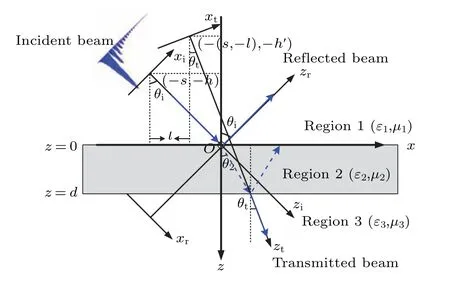
Fig.1. Coordinate system for the reflection and transmission of a finitepower Airy beam impinging on a dielectric slab.
Rather than work with a field distribution along a plane(zi=0)that is not parallel to the dielectric interface (z=0),it is more convenient to use the field distribution in the rotated aperture plane(z=-h). The electric field distribution of the Airy beam in the aperture planez=-his well approximated by

By using the Fourier transform, the spectral amplitude of the incident electric field atz=-hcan be expressed as

Based on the plane-wave angular spectrum expansion, the electric field components in each region can be derived by utilizing the integral inverse Fourier transformation. In the range of-h <z <0,the incident electric field in the global coordinate can be derived as

Meanwhile,the reflected electric field above the first interfacez=0 is

whererj(kx)is the generalized reflection coefficient.
In the global coordinate, the electric field distribution in the dielectric slabEslab,j(x,z)can be derived as[51]

whereEd,j(x,z) andEu,j(x,z) denote the electric field components of the downgoing wave and upgoing wave in region 2, respectively.Ad,j(kx) andAu,j(kx) are the coefficients of downgoing wave and upgoing wave,respectively.
The transmitted electric field in the region 3 can be expressed as

wherej=p or s, p and s denote TM wave and TE wave, respectively.tj(kx) is the generalized transmission coefficient.kxis the wavenumber in thexdirection, andk1z,k2z, andk3zseparately are the wavenumbers in each region in thezdirection,which are related by the plane-wave dispersion relation

According to the boundary condition of electromagnetic fields,the generalized reflection coefficientrj(kx) and the generalized transmission coefficienttj(kx)for the three-layer medium can be defined as[52]

Similarly,by matching the boundary conditions for the tangential electric and magnetic fields,the coefficients of downgoing waveAd,j(kx)and upgoing waveAu,j(kx)can be expressed as
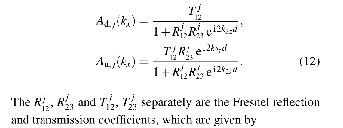


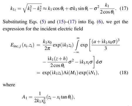
We wish to evaluate the incident electric field by using the Fresnel approximation in Eq. (14), and it is more convenient to define a new variable

from which

Substituting Eq.(15)into Eq.(14),we get

For the reflected electric field, it is more complicated compared with the incident electric field due to the generalized reflection coefficientrj(kx).rj(kx)is expanded in a Taylor series as

Substituting Eq.(15)into Eq.(20),we get

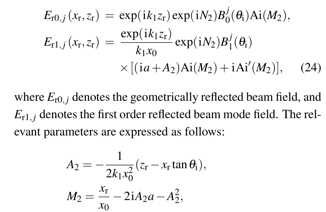
Substituting Eqs. (5), (16), (17) and (21) into Eq. (7), the reflected electric field can be calculated by using the differential properties of Fourier Transform. We obtain the following result:

andw2=-(xr/x0-2iA2a).
Due to the nonlinear properties of the generalized reflection coefficientrj(kx),the structure of the reflected field is different from the incident field. In addition to the fundamental reflected beam modeEr0,j,higher order reflected beam modesErn,jare generated.

For the transmitted beam,most of the contributions to Eq.(9)result from the region around the transmitted beam axis. By Snell’s law, we obtainkx0=k1sinθi=k3sinθt. To calculate the transmitted electric field easily,a new variable of integration is introduced

from which

Similar to therj(kx), the generalized transmission coefficienttj(kx)can be expressed in a Taylor series as


Similar to the reflected electric field, by substituting Eqs. (5)and (27)–(29) into Eq. (9), the expression for the transmitted electric field can be given as

where

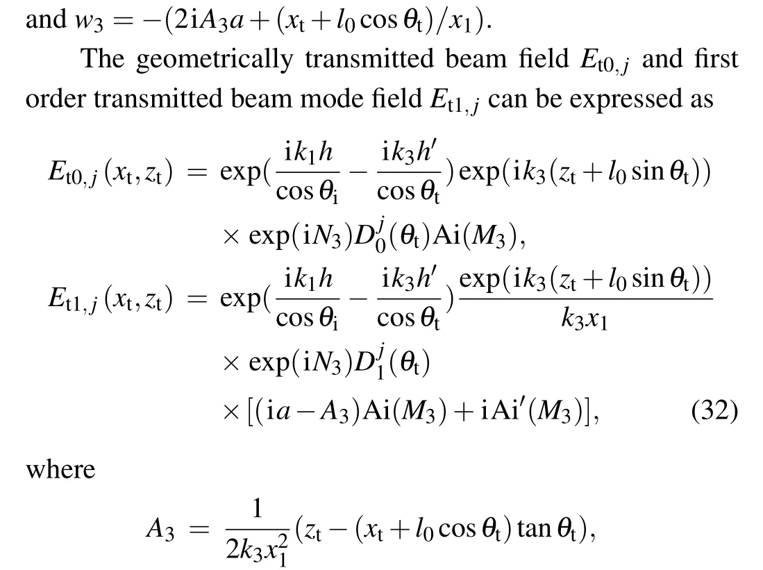

In the same way,the electric field in the dielectric slab can be derived as
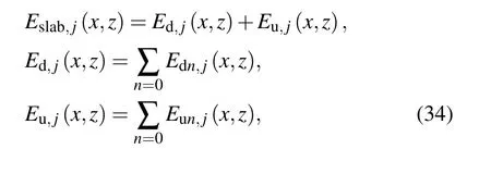

The zero and first order beam mode fields of the downgoing wave and upgoing wave can be written as


where
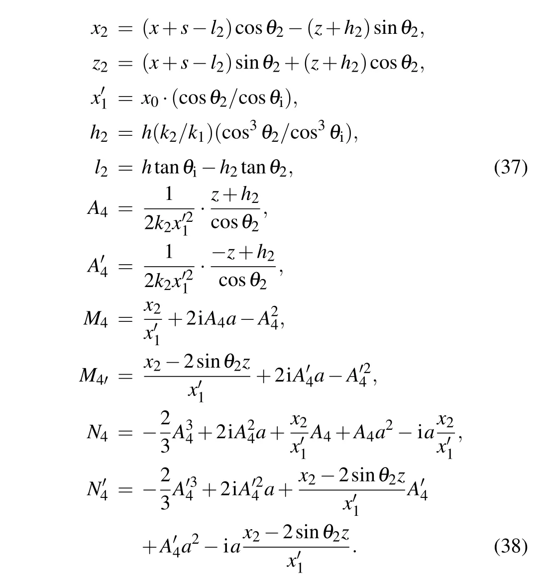
The Taylor expansion coefficients of the downgoing wave and upgoing wave can be denoted as

3. Numerical results and discussion
In this section, the characteristics of an Airy beam incident on a dielectric slab are simulated and discussed. In the following discussion we only consider a p-polarized Airy beam,withx0=20 μm,anda=0.08.The wavelength of incident beam isλ0=500 nm,and the thickness of the dielectric slab isd=50λ0. The refractive indices are set ton1=1.5 andn3=1,respectively. The diffraction length of the beam in region 1 isLd1=k1x20. Here we seth=Ld1cosθi, which allows the beam to propagate for one diffraction length before it hits the first interfacez=0.We retain the first two terms of the electric field expression,and the actual beam field is the sum of the geometrically beam field and first order beam mode field.The incident,reflected and transmitted beam axes predicted by Snell’s law separately areχi=x-ztanθi,χr=x+ztanθiandχt=(x-l0)-ztanθt,[43]respectively. In what follows, we present the intensity distributions of the incident,reflected and transmitted beams in coordinates(χi,z),(χr,z),and(χt,z),respectively.
3.1. Intensity distributions of the incident,reflected,internal and transmitted beams
According to Eq. (18), the intensity distributions of the incident beams with different incident angles are shown in Fig. 2. It is easy to find that the intensity distribution of the incident beam will not change with increase of the propagation distance due to the nondiffracting property of the Airy beam. Comparing Fig. 2(a) with Figs. 2(b) and 2(c), we can see that as the incident angles increase,the distribution area of the incident Airy beam becomes wider, but the magnitude of the incident beam will not change. Therefore, the change in incident angles will affect the width of the incident beam,but will not change the amplitude.
The intensity distributions of the reflected and transmitted beams through a dielectric slab with different refractive indexn2are shown in Fig.3.

Fig.2. Intensity distributions of the incident beams. The incident angles of the incident beams for(a),(b)and(c)are 0°,30°,45°,respectively.
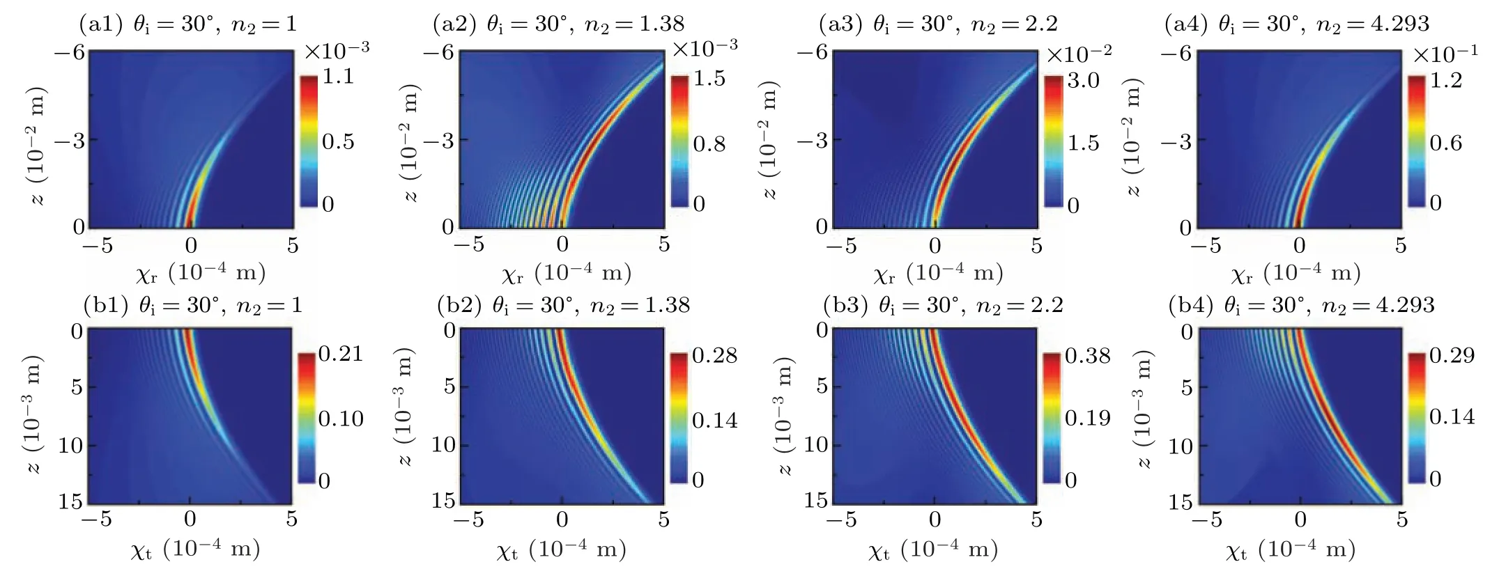
Fig.3. Impinging at angle θi=30°,intensity distributions of the reflected and transmitted beams. The first row is the reflected beams,and the second row is the transmitted beams. The refractive index of the dielectric slab for(a1), (b1); (a2), (b2); (a3), (b3); and(a4), (b4)is n2 =1,(air),n2=1.38(MgF2),n2=2.2(LiNbO3)and n2=4.293(Si),respectively.
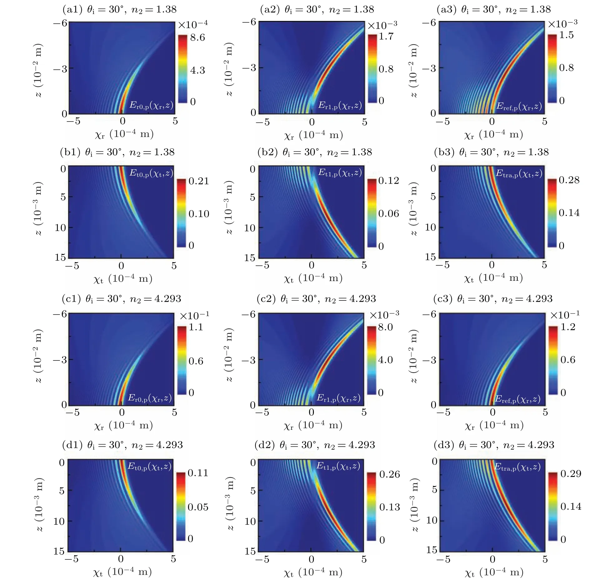
Fig.4. Impinging at angle θi=30°,intensity distributions of(a1)–(d1)for the geometrically beam field,(a2)–(d2)for first order beam mode field and(a3)–(d3)for actual beam field with n2=1.38 and n2=4.293,respectively. The first and third rows are the reflected beams,and the second and fourth rows are the transmitted beams.

Fig.5. Impinging at angle θi =30°, intensity distributions of(a)the downgoing wave, (b)upgoing wave and(c)total beam in the dielectric slab with n2=1.38.
When the refractive index of the dielectric slabn2=1,it degrades to a half-space interface. Thus, by comparing Figs.3(a1)and 3(b1)with the results shown in Ref.[43], the correctness of the method provided in this paper can be verified. In Fig. 3, It is obvious that both reflected and transmitted beams are Airy-like and exhibit accelerating dynamics along the transverse direction like the incident beam. From Figs. 3(a1)–3(a4), we can find that the main lobe’s intensity of the reflected beam increases with the refractive indexn2increasing.Atn2=1.38,the side lobe’s intensity of the reflected beam is significantly enhanced. Furthermore,due to the small Fresnel reflection coefficient, the intensity of the transmitted beam is much greater than that of the reflected beam no matter how the refractive index changes in region 2. In Figs.3(b1)–3(b4), for the transmitted beam, we can find that with the refractive indexn2increasing,the diffraction speed of the main lobe becomes slower.
Based on the Eqs. (24) and (32), we study the intensity distributions of the geometrical-optics beam field, first order beam mode field and actual beam field of the Airy beams propagating through a dielectric slab with different refractive indexn2in Fig. 4. From Figs. 4(a1)–4(d1) and 4(a2)–4(d2),we can see that the intensity distributions of the geometricaloptics reflected and transmitted beam field still maintain Airylike shape, while the intensity distributions of the first order reflected and transmitted beam mode field are significantly distorted, whose initial amplitude profile is severely destructed. For the reflected beams, comparing Figs. 4(a1)–4(a3)with Figs. 4(c1)–4(c3), we can find that the intensity of the first order beam mode field is greater than the intensity of geometrical-optics beam field atn2=1.38,and the intensity of actual beam field mainly depends on the intensity of first order beam field,while atn2=4.293,the intensity of the first order beam mode field is smaller than the intensity of geometricaloptics beam field,the intensity of actual beam field mainly depends on the intensity of geometrical-optics beam field. The change of refractive indexn2will affect the generalized reflection coefficient of the dielectric slab,and thus affect the intensity of each order beam mode field. Therefore, the refractive indexn2will affect the contribution of each order beam mode field to the actual beam field. The similar conclusion also applies to the transmitted beam case.
With Eq. (34), in the global coordinate (x,z), the intensity distributions of the downgoing wave, upgoing wave and total beam in the dielectric slab at oblique incidence are presented in Fig.5. The intensity distribution of the total beam in the dielectric slab is similar to the incident beam. Comparing Fig.5(a)with Fig.5(b),we can find that the downgoing wave intensity is much greater than the upgoing wave intensity. The intensity distributions of the total beam and downgoing wave in the dielectric slab are almost the same, which proves that the total beam intensity in the dielectric slab mainly depends on the downgoing wave in the case of incident angleθi=30°and refractive index of the dielectric slabn2=1.38.
3.2. Characteristics of the reflected beam at Brewster incidence and total reflection
It is also of interest to investigate the cases when Brewster incidence and total reflection take place on the first interface.To satisfy the conditionn2<n1sinθi<n3,[21]the refractive indices are chosen to ben1=1.5,n2=1.38 andn3=1.45(SiO2). The intensity distribution of the reflected beam when the Airy beam is incident under Brewster angleθB=42.61°in the first interface is shown in Fig. 6. From Fig. 6(a), we can find that the Airy shape of the reflected beam is distorted severely at polarizing incidence, and on the interfacez= 0 the main lobe of the beam nearly disappears but the number of side lobes increases, which is due to the Fresnel reflection coefficienthas a zero atθB=42.61°. Figure 6(b) shows the amplitude profiles of the reflected beam at different propagation distances. The initial amplitude profile is severely disturbed,while the features of Airy profile gradually recover as the beam propagates toz=-2 cm, which verifies the selfhealing property of the Airy beam.
The case when total reflection takes place on the first interface is presented in Fig.7. The critical angle of total internal reflection isθc=66.93°. Figure 7(a) shows the intensity distribution of the reflected beam in the total internal reflection case,which is a clear Airy-like shape and accelerates toward Snell’s reflection axis. The reflected beam will suffer the Goos–H¨anchen shift in the total internal reflection as shown in Fig. 7(b). We choose the peak of the reflected beam intensity as the reference point to investigate the lateral shift of the Airy beam,[53]and the shift is shown in the enlarged figure in Fig.7(b). The Goos–H¨anchen shift is calculated to be 8 μm or approximately 16 wavelengths.

Fig. 6. Impinging at Brewster angle θB =42.61°, (a) intensity distribution of the reflected beam. (b) Amplitude profiles of the reflected beam versus position χr from Snell’s reflection axis at different propagation distances.

Fig. 7. Impinging at critical angle θc =66.93°. (a) Intensity distribution of the reflected beam. (b)The amplitude profiles of the geometrically reflected beam (solid) and actual reflected beam (dashed) on the interface z=0, providing evidence to the Goos–H¨anchen shift.
3.3. Effects of optical thickness and refractive index of the dielectric slab
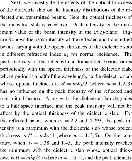

Fig.8. At normal incidence,peak intensity distributions of(a)reflected beam and(b)transmitted beam as a function of the optical thickness of the dielectric slab for different refractive index n2.

Figure 9 shows that the peak intensity of the reflected and transmitted beams varying with the optical thickness of the dielectric slab in different refractive indexn2at incident angleθi=30°. Comparing Figs. 8(a) and 8(b) with Figs. 9(a) and 9(b), we can find that at oblique incidence the peak intensity of the reflected and transmitted beams also varies periodically with the optical thickness of the dielectric slab but the period has changed, which isλ0/2cosθ2, and the extreme values of the peak intensity of the reflected and transmitted beams also change. The variation trend of the peak intensity of the reflected and transmitted beams with the optical thickness of the dielectric slab at oblique incidence is the same as that at normal incidence atn2=1.38,1.45,2.2,and 4.293. As to the effect of the refractive indexn2of the dielectric slab on the peak intensity distributions of the reflected and transmitted beams,we proceed to discuss in the following part.

Fig. 9. Impinging at angle θi =30°, peak intensity distribution of (a)reflected beam and (b) transmitted beam as a function of the optical thickness of the dielectric slab for different refractive index n2.
In order to further analyze the influence of the refractive index on the intensity distribution of the Airy beam through a dielectric slab, under special optical thickness and incident angle, the peak intensity distributions of reflected and transmitted beams varying with the refractive indexn2of the dielectric slab are presented in Fig. 10.IrandItdenote the peak intensity of the reflected and transmitted beams,respectively. From Fig. 10(a), we can see that at normal incidence,the peak intensity of the reflected beam initially decreases and then increases with the refractive indexn2increasing, while the change of the peak intensity of the transmitted beam is exactly opposite.Atn2=1.22,the peak intensity of the reflected beam reaches the minimum but the peak intensity of the transmitted beam reaches the maximum, which can be used as an antireflection film. In Fig. 10(b), at incident angleθi=30°,the peak intensity of the reflected beam first increases, then decreases and increases again,which is different from the case of normal incidence. Likewise, the change of the peak intensity of the transmitted beam is opposite to the peak intensity of the reflected beam. Atn2=1.35,the peak intensity of the reflected beam reaches the minimum and the peak intensity of the transmitted beam reaches the maximum.By choosing suitable material and thickness of the dielectric slab,many useful applications can be obtained in optical film.
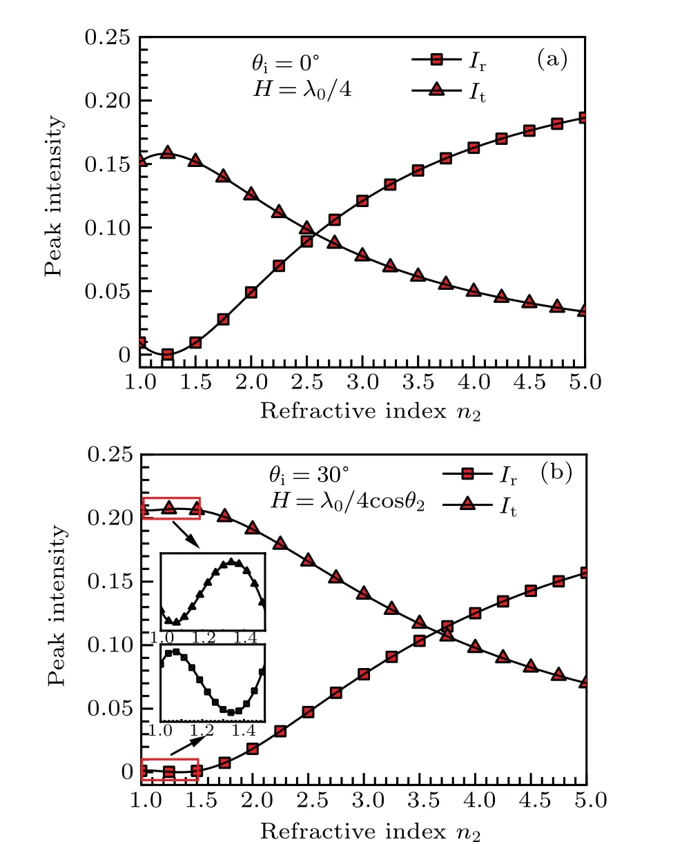
Fig.10.At normal incidence(θi=0°)and oblique incidence(θi=30°),peak intensity distributions of the reflected and transmitted beams as a function of the refractive index n2 of the dielectric slab. The optical thickness of the dielectric slab for (a) and (b) are H =λ0/4 and H=λ0/4cosθ2,respectively.
Since there are no beam shifts for the reflected and transmitted beams at normal incidence, we analyze the effects of the optical thickness and refractive index of the dielectric slab on the beam shifts of the reflected and transmitted beams at incident angleθi=30°. As mentioned above, we choose the peak of the geometrically reflected beam and actual reflected beam on the interfacez=0 as the reference point to investigate the lateral shift of the Airy beam.[53]Figure 11(a)shows that the variations of the beam shifts of the reflected and transmitted beams with the optical thickness of the dielectric slab in refractive indexn2=1.45 and incident angleθi=30°. We can notice that the beam shift of the reflected beam is on the rise overall,and there is an extreme value of the beam shift in every periodT=λ0/2cosθ2. On the contrary,the beam shift of the transmitted beam is on a downward trend as a whole with the optical thickness of the dielectric slab increasing.The beam shifts of the reflected and transmitted beams varying with the refractive index of the dielectric slab forθi=30°andH=λ0/cosθ2are presented in Fig.11(b). It is clear that the beam shift of the reflected beam first increases and then decreases as the refractive indexn2increasing. The maximum beam shift of the reflected beam is 1.2λ0at 1.92<n2<2.26.The variation trend of the beam shift of the transmitted beam with the refractive index of the dielectric slab is opposite to the beam shift of the reflected beam, and the beam shift has the maximum-0.4λ0at 1.12<n2<3.5. Our results may give a new perspective for controlling the beam shift.

Fig. 11. Impinging at angle θi =30°, beam shifts of the reflected and transmitted beams as a function of (a) optical thickness H and (b) refractive index n2 for the dielectric slab,respectively.
4. Conclusion
Based on the plane-wave angular spectrum expansion and Fresnel approximation, an analytical method have been proposed to study the reflection and transmission of a finite-power Airy beam incident in a dielectric slab. Through studying the intensity distributions of the reflected and transmitted beams at the refractive index of the dielectric slabn2=1,the correctness of the method was verified. Atθi=30°,the intensity distributions of the incident beam,reflected beam,internal beam as well as transmitted beam were simulated. Results showed that both the reflected and the transmitted beams are Airy-like shape and exhibit accelerating dynamics along the transverse direction, and the intensity of the transmitted beam is much greater than that of the reflected beam. Furthermore, the intensity distribution of each order beam mode field was also simulated. It was shown that the contribution of each order beam mode field to the actual beam field is related to the refractive index of the dielectric slab. In order to further study the interaction of Airy beam with the dielectric slab,the effects of the optical thickness and refractive index of the dielectric slab on the peak intensity and beam shifts of the reflected and transmitted beams were investigated. We found that the peak intensity of the reflected and transmitted beams varies periodically with the optical thickness of the dielectric slab,and the period is related to incident angle. Meanwhile, the variation of the peak intensity of the reflected and transmitted beams with the refractive indexn2is different for different optical thicknesses and incident angles. The results in this paper may provide some theoretical supports to the design of optical films and the verification of numerical methods, and the analytical method can also be applied to the interaction of other focused beams such as Bessel beam and Hermite-Gaussian beam with layered media.
Acknowledgements
Project supported by the National Natural Science Foundation of China(Grant Nos.62071359,61975158,62001377,and 61801349), China Postdoctoral Science Foundation(Grant No. 2016M602770), Natural Science Basic Research Plan in Shaanxi Province of China (Grant Nos. 2019JQ-405, 2019JM-238, 2020JM-192, and 2021JM-135), Natural Science Basic Research Program of Shaanxi, China(Grant No. 2020JQ-331), Postdoctoral Science Foundation in Shaanxi Province and the Fundamental Research Funds for the Central Universities, Scientific Research Program Funded by Shaanxi Provincial Education Department (Grant No. 20JS059), and the Open Foundation of Laboratory of Pinghu,Pinghu,China.
- Chinese Physics B的其它文章
- Real non-Hermitian energy spectra without any symmetry
- Propagation and modulational instability of Rossby waves in stratified fluids
- Effect of observation time on source identification of diffusion in complex networks
- Topological phase transition in cavity optomechanical system with periodical modulation
- Practical security analysis of continuous-variable quantum key distribution with an unbalanced heterodyne detector
- Photon blockade in a cavity–atom optomechanical system

