建筑设计与结构设计的关系
2022-07-01 08:49:08金箱温春
建筑技艺 2022年4期
金箱温春
在对建筑设计的整体思考中,空间、形式、肌理是由建筑设计决定的,而结构和材料则是由结构设计所遵循的力学定律决定的。换句话说,建筑设计更偏重视觉领域,而结构设计更偏重物质领域,两者的密切关系尤为重要。在良好的合作中,建筑师会思考结构,结构工程师也会思考建筑,这将有利于提升建筑的整体吸引力。本文讨论了三种建筑设计和结构设计之间的关系,同时介绍了由金箱结构设计事务所完成的一些结构设计实例。
1 结构设计与建筑设计同步推进——福井季候泥博物馆
这是一种令结构工程师激动的情况——通过建筑设计和结构设计来共同决定方案。福井的季候泥博物馆便是一个例子。展出的季候泥是在湖底堆积了7万年的淤泥,长度绵延49m,展示了过去的天气及气候状况。建筑呈条带形,9.6m宽、76m长,用来进行季候泥的展览及研究。首层是与景观相融合的大堂和架空空间。二层是展览空间,被一堵钢筋混凝土墙从中间分为6.4m宽和3.2m宽的两个空间。屋顶材料应客户要求使用当地木材。钢筋混凝土墙和屋顶的不对称性随之带来了结构的问题(图1,2)。
图3展示了整个设计过程:首先由建筑事务所制作初版模型,接下来建筑和结构事务所共同制作分析模型。第一阶段讨论结束之后确定了3号模型的结构体系。在结构概念调整之后,建筑事务所制作了4号模型。最后,双方共同完成最终模型。在整个模型制作、研究过程中,两个事务所同时思考着结构和建筑两个领域出现的问题。
在第一次讨论会上,建筑师就提出了建筑整体的造型和功能,图3-a是当时制作的模型。这是一个不对称结构,因此需要水平方向的刚度。但因为木结构很难制作刚性框架,因此需要加入对角构件。我们讨论了结构设计中的问题并研究解决办法。首先,我按照放置对角构件或系梁的思路分析了如图4所示的几类结构体系。其中,B型体系是最有效率的,但系梁会影响建筑空间的打造。F型体系设置了钢柱预埋钢筋混凝土墙,以抵抗水平力。从建筑设计角度讲,D型和F型是合适的选型。
图3-b和3-c是由我的工作室制作的可选结构类型的分析模型。我们和建筑师讨论了这些模型的建筑空间形象和机械效率。同时,建筑师研究了构件的布局并制作了相应的模型。经过与建筑师的充分讨论,我们最终选中了如图3-e所示的D型与F型相组合的结构体系。但是,这一系统还存在着纵向抗震能力差的问题。因此,如图5所示,一些对角构件被加入到倾斜的框架中,以将屋顶的地震荷载传递给钢筋混凝土墙。在材料的使用上,如果使用木材,对角构件之间的连接将会非常复杂,因此使用钢材。但不管怎样,结构体系依旧是复杂的。
最终,我和建筑师再次进行了讨论,并决定将结构体系改为如图6所示。原先的体系由木构件和钢筋混凝土墙组成,优化后的系统在木屋顶和钢筋混凝土墙之间加入了钢构件,总体来说较复杂的构件均采用了钢材。这个系统的模型由建筑事务所制作,其中,相对轻巧的钢构件支撑起体积巨大的木结构,由此结构体系和建筑形象均发生了变化(图3-f)。
图7展示了最终的结构体系:木屋顶由胶合木梁和胶合板组成,梁、对角构件和柱均采用小尺寸钢构件,钢筋混凝土墙和楼板由二层的预应力梁支撑。屋顶采用复合结构,木结构的布置简洁明了,而其下较复杂的部分则全部使用钢构件(图8,9)。
建筑呈条带形,9.6m宽、76m长,用来进行季候泥的展览及研究。首层是与景观相融合的大堂和架空空间。二层是展览空间,被一堵钢筋混凝土墙从中间分为6.4m宽和3.2m宽的两个空间。屋顶材料应客户要求使用当地木材。钢筋混凝土墙和屋顶的不对称性随之带来了结构的问题。
The building is used for exhibition and research of the varve.Therefore,the shape of the building is belt shape which has width as 9.6m and length as 76m.Material of the roof is wood of the local area requested by the client.Second floor is used for exhibition space,and there is RC wall in the center,which divides space as 6.4m and 3.2m.The asymmetrical relation of RC wall and roof has arisen structural problem.First floor is used for lobby and pilotis which is unified with landscape.

1 福井季候泥博物馆室外效果2 福井季候泥博物馆二层室内效果
首先由建筑事务所制作最初模型,接下来建筑和结构事务所共同制作分析模型。第一阶段讨论结束之后确定了3号模型的结构体系。在结构概念调整之后,建筑事务所制作了4号模型。最后,双方共同完成最终模型。
Firstly,the model was made by the architectural office.Next revised models were made by both offices.And the system as No.3 model was determined aたer the discussion of first stage.Aたer changing structural concept No.4 model was made by architectural office.Final models were made by architectural office and my office.
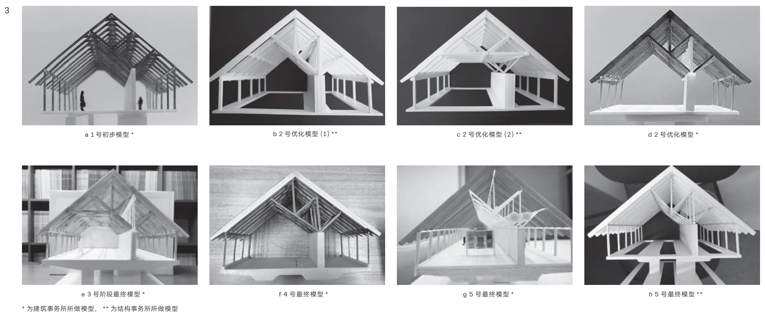
3 福井季候泥博物馆设计过程
按照放置对角构件或系梁的思路分析了几类结构体系。其中,B型体系是最有效率的,但系梁会影响建筑空间的打造。F型体系设置了钢柱预埋钢筋混凝土墙,以抵抗水平力。从建筑设计角度讲,D型和F型是合适的选型。
I researched several types of structural system shown.The idea is to place diagonal member or placing tie-beam.Type B is the most efficient,but tie beam disturbed architectural space.Type F is placed steel column embedded RC wall to resist horizontal force.Type D and F is available for architectural design.

4 福井季候泥博物馆结构研究

5 福井季候泥博物馆对角构件布置图
原先的体系由木构件和钢筋混凝土墙组成,优化的系统在木屋顶和钢筋混凝土墙之间加入了钢构件,总体来说较复杂的构件均采用了钢材。在这个系统中,相对轻巧的钢构件支撑起体积巨大的木结构,由此结构体系和建筑形象均发生了变化。
Previous system is composed of wooden members and RC wall.Improvement system is to place steel members between wooden roof and RC wall,and complicated parts are composed with steel.With this system,not only structural system but architectural image was changed as bigger wooden structure is felted to be supported by small steel members lightly.

6 福井季候泥博物馆结构系统的变化

7 福井季候泥博物馆结构系统

8 福井季候泥博物馆室外效果
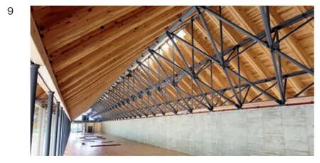
9 福井季候泥博物馆木梁和钢构件
2 建筑设计主导结构设计
在一些情况下,建筑师会优先考虑建筑的形象,而结构设计的作用只是尽可能完全地实现建筑设计。但即使是在这种情况下,结构设计也需要考虑结构效率和结构原则。以下将介绍两个项目。
2.1 京都车站中庭
京都车站的设计师选自一场国际设计竞赛。该建筑是一个大型车站综合体,包括火车站、酒店、百货商店和剧院。建筑面积达23万m,地上16层,地下3层。在建筑的中心,是一个由玻璃屋顶和幕墙组成的车站大厅。
图10 为竞赛中建筑师的手绘,展示了车站中庭的效果。左侧为平台的入口大门,钢结构由建筑结构连续支撑。右侧与车站前广场相连,墙体的钢结构由最高达20m 的组合框架支撑。人们穿过钢框架,从大厅走到站前广场。建筑师想要呈现一种特殊的结构效果——由薄钢构件组成的1.44m˜ 1.44m 的精致网格,而从结构角度来说,过窄的网格是不合理的。建成后中庭的效果几乎与建筑师的草图完全一致。结构构件是宽100mm,截面为方框的钢构件,各构件之间采用焊接的连接方式(图11,12)。
图13是钢结构的横剖面,横向均布桁架结构。图14为钢结构的立面图,标注了钢桁架的支撑点。纵向是无格栅构件的空腹结构,但是这类结构不足以支撑竖向荷载传递,也不足以抵抗地震荷载。因此,在带状空间中又加入了格栅构件。在这座建筑中,对角构件的布置十分重要,虽然有时与建筑的造型相矛盾,但也可能会实现感性的视觉效果。
2.2 青森美术馆
青森美术馆的设计灵感来源于槽沟,这种场地形态在古遗址研究中由线性开挖土壤形成。场地临近一个著名的古遗址,挖崛土被放置在建筑的底部,建造的房间被悬挂于上层。槽沟和房间之间被用作展陈空间。因此,展陈空间的形状和组织较为复杂(图15,16)。
这座建筑的结构体系非常复杂。我曾尝试着建立结构设计的规则(图17)。刚性桁架结构位于整个建筑的顶部空间,由一些通向地下室的结构核心筒支撑,许多房间悬挂其上。当悬挂的房间较大时,便会加入另一组桁架结构。
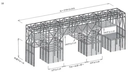
图18展示了由核心单元、屋面矩阵、墙梁和楼板单元组成的结构体系。这个分析图同时也给出了结构设计的原则。但是,真正的建筑在三维空间上是非常复杂的。我们按照规则布置了结构构件,同时制作了结构模型,用于和建筑师的交流沟通(图19,20)。
在复杂的结构中,统一结构构件尺寸是非常重要的,立柱和支柱的截面边长被统一为300mm。图21展示了施工现场的情况。复杂的结构系统依旧会遵循一定的规则,因此我认为通过一些规则来进行控制是非常重要的。
3 结构设计主导建筑设计
结构设计的构想有时会启发建筑设计的思路,这同样令结构工程师十分激动。在这种情况下,结构工程师必须对建筑设计具有深入的理解。以下将介绍两个项目。
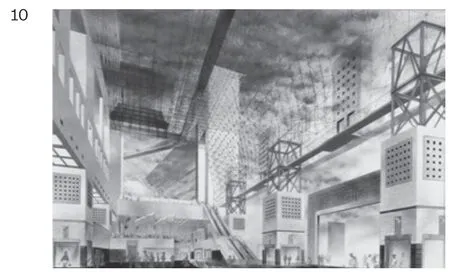
10 京都车站中庭手绘图纸
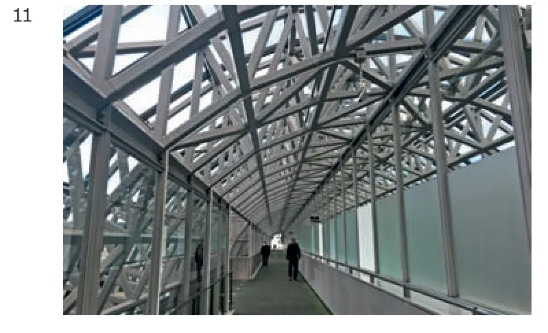
11 京都车站中庭结构构件
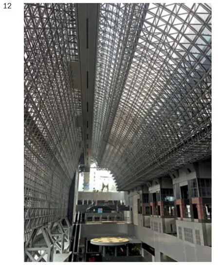
12 京都车站中庭室内效果
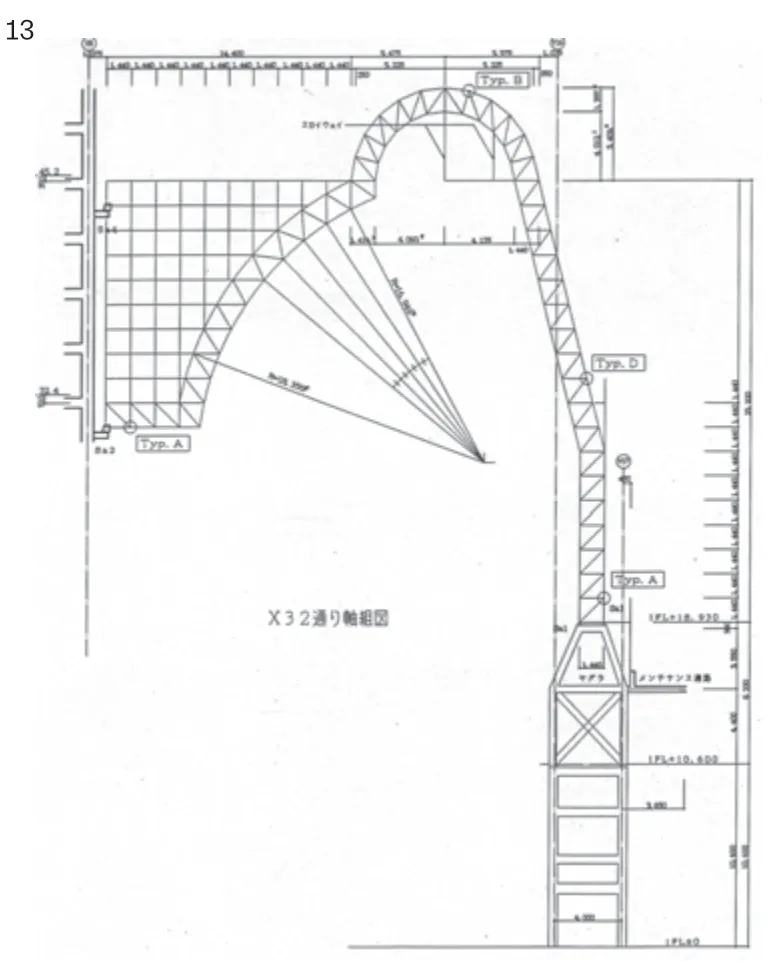
13 京都车站中庭结构横截面

14 京都车站中庭结构立面
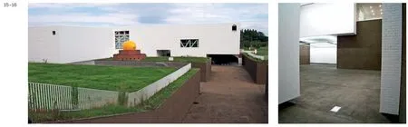
15 青森美术馆室外效果16 青森美术馆玻璃室内效果

17 青森美术馆结构设计草图
18 青森美术馆结构分析图
图18展示了由核心单元、屋面矩阵、墙梁和楼板单元组成的结构体系。这个分析图同时也给出了结构设计的原则。但是,真正的建筑在三维空间上是非常复杂的。我们按照规则布置了结构构件,同时制作了结构模型,用于和建筑师的交流沟通。
Figure 18 shows the structural system,which is composed with core unit,roof matrix,wall girder and floor unit.This diagram gives a rule of structural design.But real architecture is 3-dimnsionaliy complicated.We made structural model to show the arrangement structural elements according to the rule.This model was used for the meeting with architects.
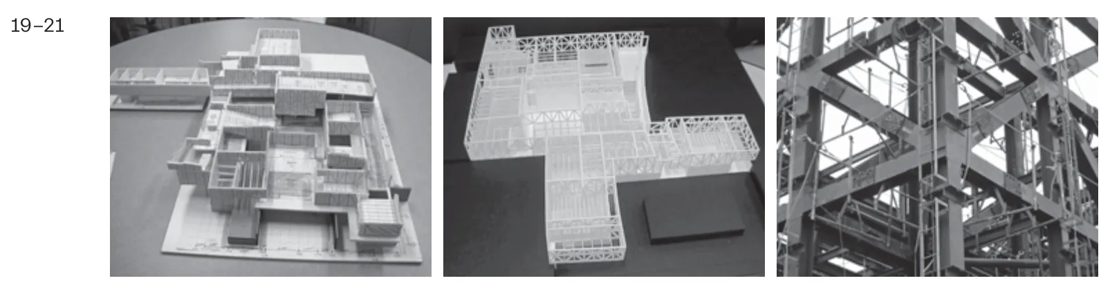
19 青森美术馆结构分析模型20 青森美术馆最终版结构模型21 青森美术馆钢结构施工现场
3.1 群马虫世界
图22是群马虫世界建筑设计初期的图纸。场地位于山脚下的斜坡,建筑的整体形象是覆盖在斜坡上的玻璃薄膜;屋顶的形状是由三条线切割出的球体的一部分。玻璃屋顶下方是蝴蝶的温室,大混凝土楼梯下方是一些观察室。这种玻璃结构需要呈现出足够通透的效果,因此使用了单层的格栅网壳,并且结构构件全部本着少而薄的设计宗旨。
图纸只能显示形式和造型,却无法说明结构设计。设计屋顶网格结构时需要确定温室条件以及构件的截面和连接方式。首先,我本着实现最优空间效果的设计原则,切割球体时,在三个方向上旋转平面,使其相交于中心点却互不重合,在表面形成三个方向的切割线。随后,我的工作室制作出如图23所示的结构模型,其中网格长度约为4m,几乎全部由相似三角形构成。在这个阶段,我调整了屋顶的高度,因为建筑设计的屋顶高度过低,以至于无法减少结构构件的受力。我希望可以通过减小构件尺寸达到透明的结构效果(图24)。
接下来,我们开始考虑支撑条件,共研究了四种情况(图25):A型在每个角部设置三个支撑构件;B型在温室周围和角部设置连续的支撑构件;C型在屋顶周边设置V形柱;D型在温室周围设置支撑构件并在周边设置V形柱。
我们对竖向荷载进行了弹性屈曲分析,屈曲系数如图26所示:B型结构因为存在局部大跨度空间,体系抗屈曲效率不高;在周边布置V形柱的C型体系非常高效;D型体系被认为是最适合这一结构的支撑方式,同时构件尺寸也被最小化。我将确定的结构网格和支撑方式提交给建筑师,他接受了我的建议并确定使用V形柱(图27)。格栅构件管径在中心区域为256mm、在周边区域为500mm,V形柱的构件管径为300mm。连接构件使用的是如图28所示的铸钢。玻璃由DPG及点状玻璃直接固定在主体结构构件上。该屋顶没有二级结构,非常简单和通透(图29)。
3.2 国营昭和纪念公园花与绿文化中心
国营昭和纪念公园花与绿文化中心是一个位于公园内的多功能建筑,平面长150m、宽30m。设计概念是打造一个位于公园内,朝向天空的带状绿色空间。建筑内部种满树木和各类植物。屋顶是一个不规则的倾斜曲面,成为建筑造型的特色所在。
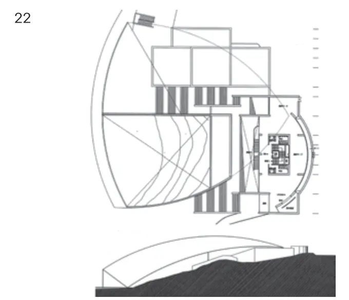
22 群马虫世界平面和立面

23 群马虫世界穹顶结构模型24 群马虫世界玻璃穹顶室外效果
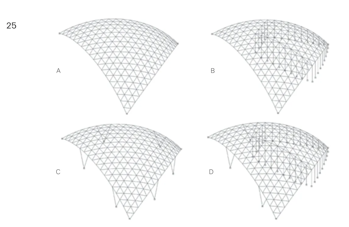
25 群马虫世界支撑条件
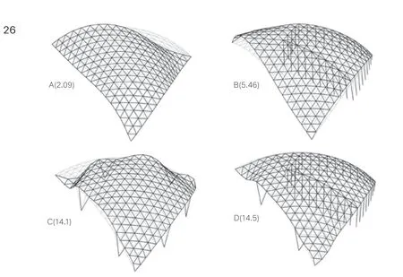
26 群马虫世界弯曲分析结果
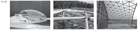
27 群马虫世界建筑模型28 群马虫世界铸钢连接构件29 群马虫世界玻璃屋顶
屋顶由两种结构支撑。一种是钢筋混凝土的环形白墙,另一种是围合成圆柱的白钢柱,这些构件被统一称为圆柱体。地震力仅由钢筋混凝土墙体抵抗。圆柱体则被随机地布置于屋顶之下(图30),内部是特定的功能空间,外部是灵活的功能空间。钢筋混凝土圆柱的布置需要在平面上寻求一个良好的平衡。
屋顶的造型几乎是平的,其上种满了树木和各种植物。由于弯矩在设计中占主导地位,因此采用钢桁架结构,通过平面网格、整体起伏、局部起伏三个步骤,确定屋顶的造型及其构件的平面布置。
项目采用平面网格的设计方法。图31是屋顶桁架平面图,圆圈表示支撑屋顶的圆柱体。连接多个圆柱体的中心点形成三角形,内部又再次进行分割,因此网格的边长趋近相同。径向构件从每个圆柱体展开,并且在另一个方向上连接到其他的构件。该网格结构利于传递竖向荷载。
屋顶采用连续扭转的条带造型。我们将纵轴方向上正弦和余弦曲线的振幅确定为1.5m,进而确定屋顶两端的高度,然后用一条直线连接屋顶两端,形成曲面,最终通过几何分析确定屋顶的整体起伏造型。
最后一步是确定屋顶局部起伏造型(图32)。圆柱支撑桁架的弯矩在靠近连接处较大。弯矩的分布决定了桁架的高度,因此桁架在大多数位置的高度为2.5m,在靠近圆柱体的位置会增高1m,即上弦杆件在圆柱体附近会被提高1m。屋顶的大部分区域被厚度约为300mm的土壤覆盖,土壤的厚度依桁架上弦杆件的起伏而发生变化,圆柱体顶部连续倾斜的地形,会形成深约1.2m的护坡,在这些位置,也会种植高大的树木。
这个体系的概念源自于结构思想,实现了结构设计、建筑设计和景观设计的统一。图33是按上述步骤制作的半屋顶模型。虽然每个步骤都很简单,但当他们结合在一起的时候,就会有一些复杂。
对构件和细部的设计同时考虑到了制作水平。在连接处垂直放置直径为150mm的钢管,桁架的弦构件和格栅构件采用200mm宽的T形杆件,被连接到用高强度螺栓连接的扣板上。不规则形状的桁架通过控制扣板的形状和位置以及桁架构件长度完成建造,使所有桁架用相同方式连接(图34-37)。
4 结论
本文共讨论了三种结构设计和建筑设计的关系。在每个项目里,这两者的关系是不同的。但即使是在建筑设计的过程中,当建筑和结构的合理性产生矛盾时,结构设计的自身逻辑也是需要被尊重的,并且结构工程师必须要始终追求结构效率并实现结构形式的优雅性。

30 国营昭和纪念公园花与绿文化中心平面图

31 国营昭和纪念公园花与绿文化中心钢桁架平面网格
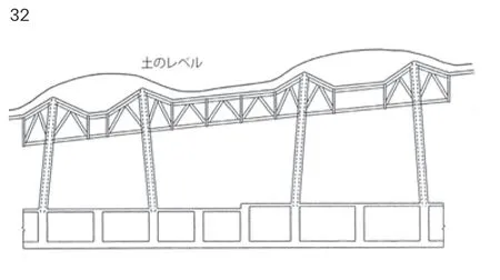
32 国营昭和纪念公园花与绿文化中心屋顶局部起伏造型
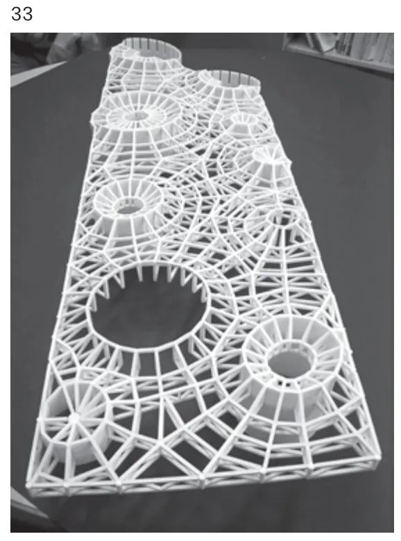
33 国营昭和纪念公园花与绿文化中心桁架结构模型

34 国营昭和纪念公园花与绿文化中心连接体系35 国营昭和纪念公园花与绿文化中心施工现场
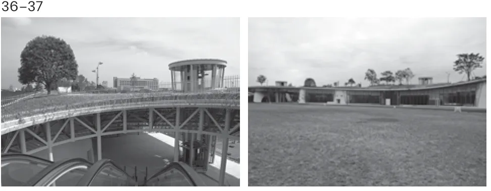
36 国营昭和纪念公园花与绿文化中心建成屋顶局部37 国营昭和纪念公园花与绿文化中心室外效果
1-7,9,11-37 金箱结构设计事务所提供
8 内藤广建筑设计事务所提供
10 原广司+Atelier Phi 建筑研究所提供
Thinking about architectural design,space,form and texture are created by architectural design,on the other hand,frame and material are determined with obeying dynamics by structural design.In another word,architectural design is an image field,and structural design is a really field.It is important that both fields make close relationship.In a good relationship,an architect thinks about structure and an engineer thinks about architecture.The close relationship between architect and structural engineer creates enhancement of architectural attraction.Three types of structural design in attention of relationship to architectural design are considered in this paper.Several structural design practices which I designed are introduced.
This case is exciting experience for structural engineer.The design is determined from not only architectural aspect but structural aspect.One example is a museum of varve at the local city in Japan.Varve is an accumulated mud at the bottom of a lake for 70 thousand years,which has 49m in length and shows the state of weather and climate condition in the past time.The building is used for exhibition and research of the varve.Therefore,the shape of the building is belt shape which has width as 9.6m and length as 76m.Material of the roof is wood of the local area requested by the client.Second floor is used for exhibition space,and there is RC wall in the center,which divides space as 6.4m and 3.2m.The asymmetrical relation of RC wall and roof has arisen structural problem.First floor is used for lobby and pilotis which is unified with landscape (photo 1,2).
Figure 3 shows the process of design.Firstly,the model was made by the architectural office.Next revised models were made by both offices.And the system as No.3 model was determined aたer the discussion of first stage.Aたer changing structural concept No.4 model was made by architectural office.Final models were made by architectural office and my office.Models were made and structural and architectural viewpoints were confirmed in both offices simultaneously.
Architectural image and function were shown by the architect at the first meeting.We talked about structural problems and how to solve the problems.I researched several types of structural system shown as figure 4.Photo 3-b and 3-c are Skelton models of structural available type made by my office.I discussed with the architect about space image and mechanical efficiency of these models.At the same time architect researched the arrangement of members and made some models.Aたer discussion with the architect combined system type D and F shown as photo 3-e were selected.But this system had another problem about earthquake resistant of the longitudinal direction.Some diagonal members were needed in the slanted frame shown in figure 5 to transfer the earthquake load of the roof to RC wall.If the diagonal members were used wood,connection of members would be complicated.we thought to use diagonal members with steel.Anyway,structural system was complicated.
I and architect discussed again and decided to change structural system shown as figure 6.Previous system is composed of wooden members and RC wall.Improvement system is to place steel members between wooden roof and RC wall,and complicated parts are composed with steel.The model of this system was made by the architect's office (photo 3-f).With this system,not only structural system but architectural image was changed as bigger wooden structure is felted to be supported by small steel members lightly.
Figure 7 shows the final structural system.The wooden roof is composed of glulam beam and plywood panel.Beams,diagonal members and columns are used steel member.Steel members are small size.RC wall and slab are supported by prestressed beams of the second floor.The structure of roof is composite structure.Arrangement of wooden structure is simple and easy;the complicated part is used with steel member.Complicated details are used only in steel members (photo 8,9).
In some cases,architectural image precedes and the role of structural design must be to realize architectural design faithfully as possible.But even if in such a case,structural design is needed to think about structural efficiency and structural rule.Two projects are introduced.
2.1 Atrium in Kyoto Station
Kyoto is the ancient capital of Japan.The architect of this building was selected by an international design competition.This building is a large station complex,which has train station,hotel,department store,and theatre.It includes 16 floors,3 basement floors and has 230 thousand square meters of floor area.In the center of the building,there is a concourse,which was covered with glass roof and wall.
Figure 10 is the image drawing of the atrium,which was drowned by the architect for the competition.There is the entrance gate of the platform at the leた side,and the steel structure is supported by building structures continuously.The right side is connected to the plaza in front of the station,and the steel structure of the wall is supported by combined frames as the pitch of 20m.The architect wanted to make a special structure,which has delicate grid as 1.44m by 1.44m and composes with thin steel members uniformly.This image is not structurally rational because the grid is too narrow.The image of architecture is almost fit to the sketch of the architect.The structural member is 100mm wide steel square box section,and the members are connected by welding (photo 11,12).
The basic arrangement of the longitudinal structure is Vierendeel structure without lattice members.But the strength of this type structure is not enough to transfer vertical load to the support points and to resist seismic load.Therefore,lattice members are added at belt shape zone in order to transfer load to the support point and to resist seismic load (figure 13,14).In this architecture,arrangement of diagonal member is important.Placing diagonal members partially are in conflict with uniform image of architecture,but it is possible to realize architectural sensitive image.
2.2 Aomori Museum of Art
The next example is Aomori Museum of Art shown as photo 15 and 16.The motive of design of this architecture was arisen from Trench,which is the condition of digging soil linearly for researching ancient ruins.The
site is located near a famous ancient ruin,so Trench was selected a motive.Digging soil is placed at the lower part of the building and artificial rooms are hung from the upper structure.The spaces between trench and artificial rooms are used for exhibition space.Therefore,the shape and arrangement of exhibition space is complicated 3-dimensinally.
The structure system of this architecture must also be complicated.I tried to establish the rule of structural design.Figure 17 is the idea of structural design for this architecture.The rigid truss structure is placed at the whole area of the top of the building.The truss is supported by several structural core stranded from basement.Many rooms are hung from roof truss.When the volume of hanged room is bigger,other truss structures are added at the hung rooms.Figure 18 shows the structural system,which is composed with core unit,roof matrix,wall girder and floor unit.This diagram gives a rule of structural design.But real architecture is 3-dimnsionaliy complicated.We made structural model to show the arrangement structural elements according to the rule.This model was used for the meeting with architects (photo 19,20).
It is important to unify structural element size with complicated structure.Columns and bracing were unified the size as 300mm.Photo 21 is the scenery of construction.The structural system became complicated finally,but it is obeyed a rule.I think even if the structure is complicated,it is important to control with some rules.
Sometimes structural thinking arises architectural design idea.It is exciting situation for structural engineers.Structural engineers must deeply understand for architectural design in this case.Two projects are introduced.
3.1 Gunma Insect World
Figure 22 is the architectural drawing in basic design phase.The building site is in a slope at the base of a mountain.The image of the architecture is a thin glass membrane covered on the slope;the roof shape is cut part of a sphere by three lines.There is the hothouse for butterflies under the glass roof.There are several observation rooms under the concrete large stair.This glass structure was needed transparency,therefor the structure is single layer lattice shell,and the structure members were hoped less and thin.
This drawing indicated form and image,but didn’t indicate structural element.On structural design,making grid of the roof,determining support condition considered the hothouse,and determining member section and connection were needed.Firstly,I tried making the grid of the roof considering to appear the perimeter zone elegant.Rotating planes in three directions as cutting the sphere makes three direction lines at the surface of the sphere.Three lines cross the same point at center area,but are not coincident at perimeter area.The lines are arranged to coincident the cross point of the three lines.Aたer that,three-dimensional structural model showed photo 23 was made in my office.The grid length is about 4m.The shapes of triangle are almost the same form.In this stage,I arrange the height of the roof,because the height of the roof of architectural drawing is too low to reduce stress of members.I wanted to make member size smaller to realize a transparent structure (photo 24).
Next,the support condition was considered.Four cases of support condition were considered (figure 25).
Type A:There are three supports at each corner.Type B:There are continuous supports around the hot house and corners.Type C:There are the V shaped columns in the perimeter of the roof.Type D:There are supports around the hot house and the V shaped columns in the perimeter.
The elastic buckling analysis about vertical load was done and the buckling coefficient is shown in figure 26.The support of type D which is used vertical columns around the hothouse and V shape columns in the perimeter is thought suitable for this structure.The member size was minimalized by this structural system.I proposed to the architect the structural grid and the support condition.He accepted my proposal and made the design using V-shaped columns(photo 27).The member of lattice is pipe as 256mm diameter at the center area and pipe as 500mm diameter at the perimeter,and the member of V-shaped column is pipe as 300mm diameter.Connection is used with cast steel shown as photo 28.Glasses are fixed directly (on) main structural member by DPG,dot point glazing.There is not secondary structure.It is very simple and transparency roof (photo 29).
3.2 Showa Kinen Park Hanamidori Cultural Center
Another example is Showa Kinen Park Hanamidori Cultural Center.The building,which was planned within a park,is a multiuse facility with a 30m wide by 150m long planar size.The architectural design concept is a band of green space within the park;liたed upward toward the sky with trees and various plants.The building has irregularly shaped rooたop that incorporates slanted and curved surface.
The roof is supported by two types of the structure.One is white walls with cylinder shape made of RC,another is aggregates of white steel columns with cylinder shape.These elements were named cylinder.Seismic force is resisted only by the RC wall-structured cylinders.The cylinders were placed at random under the roof (figure 30).The inside of the cylinders are specific function spaces,the outer of the cylinders is provided flexible functions.It was important to place the RC wall cylinders in a good balance planarly.
The roof is configured so as to be nearly flat.There are plants and trees on the roof.Because the bending moment is dominant,a steel truss structure was used.The roof configuration and the layout of the members were important for this project and it was determined through the following three operations:planar grid,overall undulation of the roof and localized undulation shape of the roof.First,method of making planar grid is introduced.Figure 31 is the plan of the roof truss.The circles indicate cylinders which support roof.A triangular shape that joined the center points of multiple cylinders was formed,and the inside of each triangle was divided so that the length of the grid
was almost equal.A radial direction member expands from each of the cylinder,and connects to the member from other direction.This grid fits the flow of force for vertical load.
The overall undulation shape of the roof is continuously twisted belt.The height of both ends of the longitudinal direction were determined by sine and cosine curves with amplitude of 1.5 m.Then both ends were connected with a straight line to form surface.The undulation of the overall roof shape was determined with geometry.
Finally,the localized undulation shape of the roof is determined (figure 32).The bending moment diagram of the truss supported by the cylinder is bigger near the cylinder.If the height of the trusses is determined by the distribution of the bending moment,the height of the truss in general portions was 2.5m,and the height of the truss near the cylinder added 1m.The upper chord members are liたed 1m near the cylinder.The roof was covered with soil to a thickness of about 300mm in general areas.The soil level was also varied in accordance with the undulation of the upper chord members of the trusses,and an incline was continued at the top of the cylinders to create an embankment of about 1.2m depth.Large woods were planted in these portions.
This system was introduced from structural idea,and the structural design,the architectural design and the landscape design were unified by this method.Photo 33 is the model of half of the roof based on the rules.The three rules are simple,but when those rules are combined the result is a little complicated.Member components and details were designed in consideration of the fabrication.Steel pipes having a diameter of 150mm were placed vertically at the connection.The chord members and lattice members of the trusses were used a 200mm wide series of T-section members.T-section members were attached to gusset plates connected with high strength bolts.The irregularly shaped trusses were built by controlling the shape and positioning of the gusset plates and the length of the truss members.The basic method to make truss connection is only one type (photo 34-37).
Three types of structural design are considered in attention of relationship to architectural design in this paper.The relationship structural design and architectural design is variable in every project.Even if architectural design proceed has contradiction of structural rationality,philosophy of structure design is needed,and structural engineers must seek structural efficiency and realize structural elegancy.
猜你喜欢
扬子江(2023年6期)2023-11-11 11:06:48
设备管理与维修(2022年21期)2022-12-28 07:34:28
今日农业(2022年1期)2022-11-16 21:20:05
现代装饰(2020年6期)2020-06-22 08:44:12
四川文学(2020年11期)2020-02-06 01:54:20
制造技术与机床(2019年11期)2019-12-04 05:50:48
儿童时代·幸福宝宝(2019年1期)2019-03-31 15:00:22
天津诗人(2017年2期)2017-11-29 01:24:14
制造技术与机床(2017年4期)2017-06-22 11:17:56
诗潮(2017年2期)2017-03-16 19:57:57