
Single-polarization single-mode hollow-core negative curvature fiber with nested U-type cladding elements
2022-06-29 09:18:50QiWeiWang王启伟ShiQiu邱石JinHuiYuan苑金辉GuiYaoZhou周桂耀ChangMingXia夏长明YuWeiQu屈玉玮XianZhou周娴BinBinYan颜玢玢
Chinese Physics B 2022年6期
关键词:吴强
Qi-Wei Wang(王启伟) Shi Qiu(邱石) Jin-Hui Yuan(苑金辉) Gui-Yao Zhou(周桂耀)Chang-Ming Xia(夏长明) Yu-Wei Qu(屈玉玮) Xian Zhou(周娴) Bin-Bin Yan(颜玢玢)
Qiang Wu(吴强)4,‡, Kui-Ru Wang(王葵如)1, Xin-Zhu Sang(桑新柱)1, and Chong-Xiu Yu(余重秀)1
1State Key Laboratory of Information Photonics and Optical Communications,Beijing University of Posts and Telecommunications,Beijing 100876,China
2Research Center for Convergence Networks and Ubiquitous Services,University of Science&Technology Beijing,Beijing 100083,China
3Guangzhou Key Laboratory for Special Fiber Photonic Devices,South China Normal University,Guangzhou 510006,China
4Department of Physics and Electrical Engineering,Northumbria University,Newcastle upon Tyne,NE1 8ST,United Kingdom
Keywords: hollow-core negative curvature fiber,single-polarization,single-mode,finite element method
1. Introduction
Hollow-core negative curvature fiber (HC-NCF), whose surface is perpendicular to the boundary of the core, is opposite to the radial unit vector in the cylindrical coordinate system, and their transmission mechanism results from the anti-resonance reflection.[1–6]Unlike the hollow-core photonic bandgap fiber (HC-PBGF), there is no periodically arranged cladding structure in the HC-NCF.[7–11]In addition,the HC-NCF has a broader bandwidth and lower transmission loss because of its large core diameter and special transmission mechanism.[12–17]For an optical communication system, if the optical fiber has good single-polarization characteristic, it can avoid the effects of the polarization mode dispersion and crosstalk between the polarization modes during transmission.[18–20]In recent years,some investigators did their best to achieve the single-polarization characteristics of the NC-HCFs.[21–25]Now, there are the two main methods to design the single-polarization HC-NCFs. The first method is to introduce the symmetrical refractive index distributions.By filling or coating high refractive index materials in the cladding tubes in one direction,the coupling strength between the fundamental mode(FM)and silica modes(SMs)in the direction will be enhanced, which leads to a high confinement loss (CL).[26,27]The other method is to design a symmetrical geometric structure. By keeping the thickness of the silica tubes in one direction to meet the resonance condition, while the thickness of the silica tubes in the other direction meet the anti-resonance condition. At this time, the coupling strength between the FM and SM in one direction will be enhanced and restrained in the other direction.[21,22,28]
In 2015,Mousavi and Richardson reported a nested antiresonance nodeless fiber(NANF)with four silica tubes,which is the first single-polarization anti-resonant fiber. The polarization extinction ratio (PER) is approximately 1000 and lowest-loss polarization is 0.075 dB/m.[21]In 2018, Weiet al.demonstrated the polarization-maintaining NCFs with six silica tubes. By introducing the resonant thickness on the nested tubes in they-polarization direction, the PER is 850,and the lowest-loss polarization is 0.02 dB/m at wavelength 1550 nm.[23]In 2018, Yanet al.[24]proposed a double-ring HC-NCF with six tubes. By introducing resonant thickness on the inner tubes in thex-polarization direction, the PER is 17662, and the lowest-loss polarization is 0.04 dB/m at wavelength 1550 nm. Besides, this proposed HC-NCF has a good single-mode transmission performance with a high-order mode extinction ratio (HOMER) of 393.[24]In 2020, Yerolatsitiset al.fabricated a single-mode birefringent NCF with six silica tubes. By introducing different tubes in thickness in thexdirection, the measured CL is 0.46 dB/m at wavelength 1550 nm with a birefringence of 2.5×10⁻⁵.[25]From the previous researches,the high-order mode suppression and low loss characteristics can be significantly improved by introducing the elliptical silica tubes in the cladding region in comparison with the case of circular silica tubes.[29,30]
In this paper, we propose a single-polarization singlemode HC-NCF with nested U-type cladding elements. The influences of the structure parameters on the PER and CL are investigated by the finite element method (FEM). In this design, to guarantee the low CL, we first introduce the eight elliptical cladding silica tubes, whose thickness meet satisfy the anti-resonance condition. Second, in order to achieve the single-polarization characteristic, we add the two U-type silica elements in they-polarization direction, whose thickness meet the resonance condition. Thus, it satisfies not only the asymmetry of the tube thickness in the two transverse orthogonal directions, but also the asymmetry of the tube shape.The simulation results show that the proposed HC-NCF can achieve single-polarization single-mode guidance with a PER of 25749 and an HOMER of 174.Moreover,thex-polarization fundamental mode loss of the HC-NCF is only 0.0015 dB/m,and the HC-NCF shows a good bending-resistance.
2. Design of single-polarization single-mode HC-NCF and performances
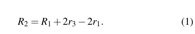
The cross-section of the proposed HC-NCF is shown in Fig.1. Compared with the traditional nested tube HC-NCFs,such a U-type nested tube structure can avoid the high refractive index points caused by the connection between the outer tube and nested tube. Therefore, the lower CL for the HCNCF can be achieved. As shown in Fig.1,the major axial radius and minor axis radius for each of the two elliptical tubes in theydirection arer1andr2, respectively. The arc part of the nested U-type silica tube is a semicircle, whose radius isr5, and the distance between the bottom of the U-typed silica tube and the top of the outer silica tube is 2r5. The other six elliptical cladding silica tubes have the same major axis radiusr3and minor axis radiusr4. There are two kinds of tubes. The thickness for each of the two U-type nested silica tubes(green color)ist2,and the thickness of the remaining tubes ist1. The inner core radius and outer core radius are denoted asR1andR2. And the relationship betweenR2and other parameters can be described as
The transmission mechanism of the HC-NCFs results from the anti-resonant reflecting optical waveguide(ARROW)mode.[11]When the fiber structure satisfies the resonance condition,the thickness of the silica tubes can be obtained from
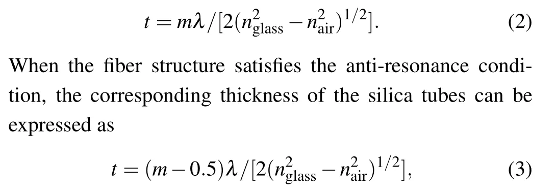
where the positive integermis the resonance order,λ(in unit nm) is the operating wavelength,nglassis the refractive index of the silica,andnairis the refractive index of the air.
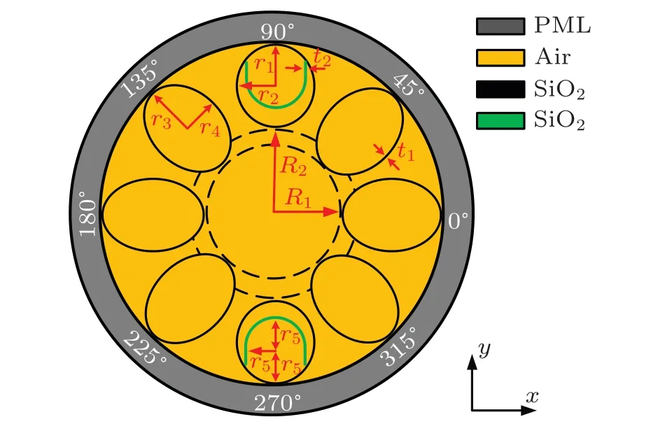
Fig. 1. Cross-section structure of designed single-polarization singlemode HC-NCF with nested U-type cladding elements.
When the FM is coupled with the SM,the CL of the FM will increase. The CL can be obtained from[3]
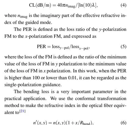
wheren′(x,y) is the equivalent refractive index,n(x,y) is the original refractive index,andRbendis the bending radius.Here,we assume that the bending direction is along thexaxis.
In this work,the low loss and single-polarization characteristics of the proposed HC-NCF can be achieved by adjusting the structure parameters. For the outer rings of the two silica tubes in theydirection, the tube thickness is set to be the anti-resonant thickness to ensure the low CL of the FM.To introduce the single-polarization characteristic, the thickness values of the two nested U-type tubes in theydirection satisfy the resonance condition. According to Eqs. (2) and(3), form=2,t1=1.12 μm is an anti-resonant thickness at wavelength 1550 nm,andt2=1.5 μm is a resonant thickness at wavelength 1550 nm. Thus, the initial structure parameters of the HC-NCF are set to beR1=16 μm,r1=15 μm,r2= 13 μm,r3= 19 μm,r4= 15 μm,r5= 15 μm,t1=1.12 μm, andt2= 1.5 μm. The FEM is adopted to simulate the proposed HC-NCF. In this simulation, the perfectly matched layer(PML)is added to the outermost layer,the grid size of the air area is set to beλ/3,and other silica regions are assumed to beλ/6.
Figures 2(a)and 2(b)show the calculated mode field distributions of they-polarization silica mode (SM1) at wavelength 1540 nm andx-polarization silica mode(SM2)at wavelength 1554 nm, respectively. Figures 2(c) and 2(d) show the mode field distributions of they-polarization fundamental mode(FM1)at wavelength 1552 nm andx-polarization fundamental mode(FM2)at wavelength 1556 nm,respectively.
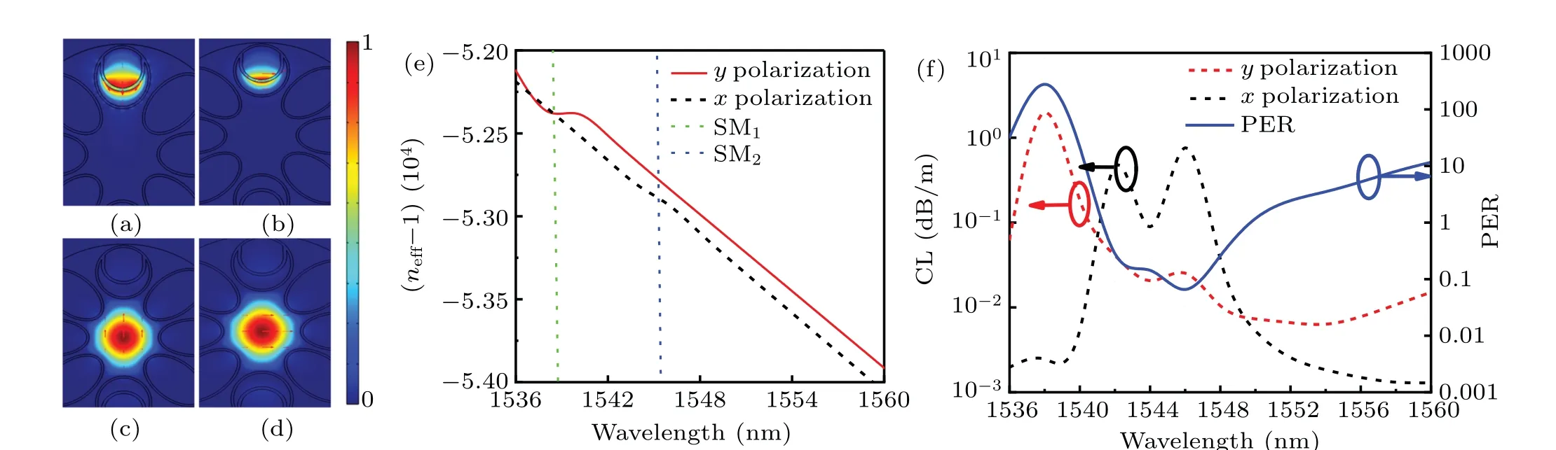
Fig.2. (a)–(d)Mode field distributions of SM1 at wavelength 1540 nm,SM2 at wavelength 1554 nm,FM1 at wavelength 1552 nm,and FM2 at wavelength 1556 nm. (e)Effective refractive index curves of x-polarization and y-polarization FMs and two SMs. (f)CL curves of x-polarization FM and y-polarization FM,and the corresponding PER.
Figure 2(e)shows that the SM1is coupled with the FM1at wavelength 1538 nm,whereas the SM2is coupled with the FM2at wavelength 1546 nm. Figure 2(e) shows the plots of the real part of the effective refractive index of thexpolarization FM,y-polarization FM and two SMsversuswavelength. At wavelength 1538 nm, the effective refractive index curves of the FM1and SM1intersect, and the FM1is coupled with the SM1at this time. At wavelength 1546 nm,the effective refractive index curves of the FM2and SM2intersect, and the FM2is coupled with the SM2at this time.Figure 2(f) shows the CL curves of thex-polarization andypolarization FMs and their corresponding PER.As seen from Fig. 2(e), when the FM1is coupled with the SM1at wavelength 1538 nm, the CL of the FM1increases, but the CL of the FM2changes slightly. When the FM2is coupled with the SM2at wavelength 1546 nm, the CL of the FM2increases,while the CL of the FM1changes slightly.Whenλ=1550 nm,the PER is 102, and the CL is 0.017 dB/m. In the following,we will discuss how to improve the PER and reduce the CL around 1550 nm.
3. Influences of fiber structure parameters on propagation characteristics
To obtain the higher PER and lower CL, the influences of the fiber structure parameters need discussing. From the analysis in Section 2,it is known thatt1has the greatest influence on the CL andt2has the greatest influence on the PER.Thus, we first fixt1at a determined value and study the influence oft2on the PER.Figure 3(a)shows the plots of PER calculatedversus t2, witht1fixed separately at 1.116, 1.118,and 1.12 μm. It can be seen from Fig. 3(a) that with the increase oft2, the PER peak wavelengths are shifted, but the PER peak can be obtained by adjusting the value oft1andt2reasonably. Therefore, a pair oft1andt2can be chosen to obtain a better single-polarization characteristic. We chooset1=1.116 μm andt2=1.51 μm to obtain the highest PER according to Fig. 3(a). Figure 3(b) shows the CL of thexpolarization andy-polarization FMs and corresponding PER whent1is fixed at 1.116 μm at wavelength 1550 nm. It is found that whent2=1.51 μm,the CL of thex-polarization FM is the lowest and the CL of they-polarization FM is the highest . Ast2changes, the CL of thex-polarization FM experiences a small change,but the CL of they-polarization FM has a great change. The main reason is that whent2changes, the coupling wavelength and coupling degree of they-polarization FM and SM1will change, which will result in the change of the wavelength corresponding to the high loss point in theypolarization direction and PER.
Figure 4(a) shows that the PER and CL of the proposed HC-NCF vary with wavelength in a range from 1545 nm to 1555 nm for three different values oft1. Whent1increases from 1.116 μm to 1.12 μm, a red-shift happens to the PER peak wavelength,and the PER peak value decreases. The reason is that with the increase oft1, the coupling wavelengths of they-polarization FM and SM1will trigger off a red-shift,and the coupling degree will decrease. However, the CL has little change whent1changes. Figure 4(b)shows that the PER and CL vary with wavelength in a range from 1545 nm to 1555 nm for three different values oft2. Whent2increases from 1.51 μm to 1.514 μm, a red-shift happens to the PER peak wavelength,and the PER peak value increases. The reason is that with the increase oft2,the coupling wavelength of they-polarization FM and SM1will set up the red-shifts and the coupling degrees will increase.However,whent2changes,the CL has little change.

Fig.3. (a)Plots of PER versus t2, with t1 fixed separately at 1.116, 1.118,and 1.12 μm at wavelength 1550 nm. (b)Plots of CL of the x-polarization and y-polarization FMs and corresponding PER versus t2, with t1 fixed at 1.116 μm at wavelength 1550 nm.
Figures 5(a)–5(f) show the calculated PERs and CLs of the proposed HC-NCF whenr1,r2,r3,r4,r5, andR1are changed,respectively. From Fig.5(a),whenr1increases from 14.5 μm to 15.5 μm, these PER peak wavelengths give rise to red-shifts,and are located at 1549,1551,and 1552 nm,respectively, corresponding to the PER values of 1561, 16772,and 1310. From Fig. 5(b), whenr2increases from 12.5 μm to 13.5 μm, the PER peak wavelengths cause red-shifts, and are located at 1549,1551,and 1552 nm,respectively,with the PER values being 526, 16772, and 533. Figure 5(c) shows that whenr3increases from 17.5 μm to 18.5 μm, the PER peak wavelengths present red-shifts, and are located at 1550,1551, and 1551 nm, respectively, with the PER values being 5267,16772,and 21287.Figure 5(d)indicates that whenr4increases from 18.5 to 19.5 μm,the PER peak wavelengths have small shifts and are located at 1551 nm, with the PER values being 11287,16772,and 29735. From Fig.5(e)it follows that whenr5increases from 14.5 μm to 15.5 μm, the PER peak wavelengths have blue shifts, and are located at 1552, 1551,and 1548 nm, respectively, with the PER values being 317,16772, and 497. From Fig. 5(f) it follows that whenR1increases from 15.5 μm to 16.5 μm,the PER peak wavelengths set up red-shifts, and are located around 1551 nm, with the PER values being 5036, 16772, and 27007. The main reason can be that asr1,r2,r3,r4,r5orR1change,the coupling wavelength and coupling degree of they-polarization FM and SM1will change,which will result in the change of the wavelength corresponding to the high loss point in they-polarization direction and PER. However, from Figs. 5(a)–5(f), the CL has little change whenr1,r2,r3,r4,r5orR1change. In summary,it can be concluded that whent1andt2are fixed, the other structure parameters of the proposed HC-NCF have different effects on the PER.
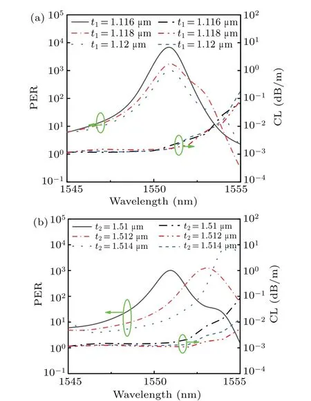
Fig.4. Curves of PER and CL,(a)with t1 being 1.116,1.118,and 1.12 μm.and t2 being 1.51 μm,and(b)with t2 being 1.51,1.512,and 1.514 μm and t1 being1.116 μm separately.

Fig.5. Curves of PER and CL(a),with r1 being 14.5,15,and 15.5 μm; (b)with r2 being 12.5,13,and 13.5 μm; (c)with r3 being 17.5,18,and 18.5 μm;(d)with r4 being 18.5,19,and 19.5 μm;(e)with r5 being 14.5,15,and 15.5 μm;and(f)with R1 being 15.5,16,and 16.5 μm,separately.
4. Transmission performances of proposed HCNCF
Based on the above analyses,the final structural parameters of the HC-NCF are determined as follows:R1=16 μm,r1= 15 μm,r2= 13.2 μm,r3= 19 μm,r4= 15.3 μm,r5=15 μm,t1=1.115 μm, andt2=1.507 μm. Figure 6(a)shows the variations of real parts of the effective refractive indices of thex-polarization andy-polarization FMs and two SMs with wavelength. It can be seen from Fig. 6(a) that at wavelengths 1522,1529,and 1550 nm,the effective refractive index curves of they-polarization FM and SM1intersect,and the effective refractive index curve of they-polarization FM has a sudden change. At 1556 nm,the effective refractive index curves of thex-polarization FM and SM2intersect, and the effective index curve of thex-polarization FM has a sudden change. In Fig. 6(c), at wavelengths 1522 nm, 1529 nm,and 1550 nm, the effective refractive index curve of theypolarization FM has a sudden change, and the CL of theypolarization FM will increase sharply. In contrast, the CL of thex-polarization FM changes slightly.And at 1556 nm,when the effective refractive index curve of thex-polarization FM has a sudden change,the CL of thex-polarization FM will increase sharply, but the CL of they-polarization FM changes slightly. In Fig. 6(d), there will be extreme values of the PER respectively near the wavelengths 1522 nm, 1529 nm,1550 nm,and 1556 nm,and there exist two single-polarization regions in the wavelength range from 1521 nm to 1522 nm and from 1548 nm to 1551 nm.
Besides,at 1550 nm,the PER is 25749,and the CL of the FM is 0.00152 dB/m.
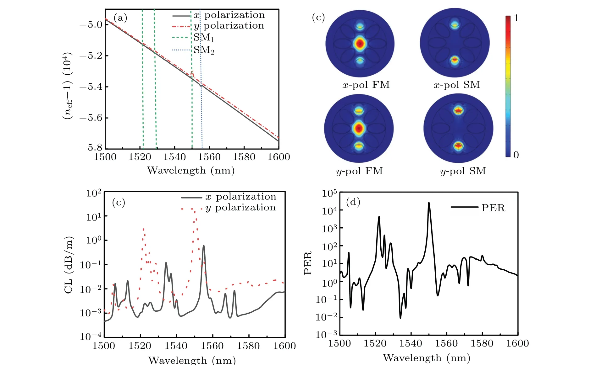
Fig.6. (a)Wavelength-dependent effective refractive indices of x-polarization(x-pol)and y-polarization(y-pol)FMs and two SMs;(b)electric field distributions of x-polarization FM, x-polarization SM at wavelength 1556 nm and y-polarization FM, y-polarization SM at wavelength 1550 nm;(c)wavelength-dependent loss of x-polarization and y-polarization FMs;and(d)wavelength-dependent PER.
In this work,the HOMER is defined as the minimum loss ratio of the loss of the higher-order modes to the fundamental loss. At 1550 nm, the HOMER is 174, so the proposed HC-NCF can be regarded as the single-mode guidance.
5. Bending loss characteristic of proposed HCNCF
Figure 7(a) shows the bending loss of the FM1and the FM2, which are represented, respectively, by the red curve and the dark curve at wavelength 1550 nm. The extreme forRbending=5 cm is caused by the phase-matching between the core mode and cladding mode after bending for the two fundamental modes. Figures 7(b)–7(d) show the mode field distribution of thex-polarization FM calculated withRbending=2,5,and 8 cm. It can be found from Figs.7(b)–7(d)that when the HC-NCF is bent along thexpolarization with different values ofRbending,the mode field energy can be well confined in the core region of the HC-NCF.
Table 1 shows the comparison between the results of the PER,CL,and HOMER of the proposed HC-NCF and the results of other researches. It can be seen from Table 1 that the proposed HC-NCF has the highest PER and the lowest CL.Thus, it has good single-polarization single-mode transmission characteristic.
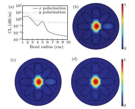
Fig. 7. (a) Curves of calculated bending loss at wavelength 1550 nm, and(b)mode-field distribution of x-polarization FM separately with Rbending =2 cm,(c)5 cm,and(d)8 cm.
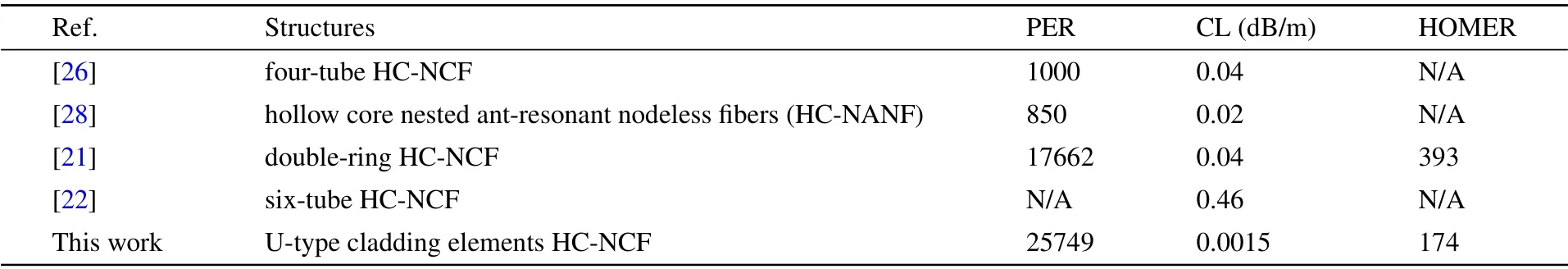
Table 1. Comparison of results between proposed HC-NCF and other researches.
6. Conclusions
In this work, we proposed a novel single-polarization single-mode HC-NCF that includes two nested U-typed silica tubes. When the fundamental mode and the nested U-typed silica tube mode in the same polarization direction are coupled with each other, the CL of the fundamental mode in the polarization direction will increase,and the PER will increase at the same time. The simulation results show that for the proposed HC-NCF, the CL is only 0.0015 dB/m, the PER can reach 25749,and the HOMER is 174. The proposed HC-NCF has a good single-polarization single-mode transmission characteristic. It is believed that such an HC-NCF will be very useful in transferring the data and energy.
Acknowledgement
Project supported by the National Natural Science Foundation of China(Grant No.61935007).
猜你喜欢
传奇·传记文学选刊(2024年5期)2024-05-17 07:14:53
中国篆刻·书画教育(2021年2期)2021-04-06 03:26:15
民间文学(2019年7期)2019-08-05 18:20:54
当代贵州(2019年18期)2019-07-26 02:03:32
汽车维修与保养(2017年3期)2017-06-24 13:11:21
世纪(2016年2期)2016-09-06 05:30:00
Journal of Donghua University(English Edition)(2015年4期)2015-08-07 10:54:14
水动力学研究与进展 B辑(2014年2期)2014-06-01 12:30:00
外科研究与新技术(2011年3期)2011-08-15 00:54:32
新民周刊(2011年44期)2011-05-30 10:48:04
- Chinese Physics B的其它文章
- Switchable terahertz polarization converter based on VO2 metamaterial
- Data-driven parity-time-symmetric vector rogue wave solutions of multi-component nonlinear Schr¨odinger equation
- Neutron activation cross section data library
- Multi-phase field simulation of competitive grain growth for directional solidification
- A novel similarity measure for mining missing links in long-path networks
- Effects of electrical stress on the characteristics and defect behaviors in GaN-based near-ultraviolet light emitting diodes