Innovative hydrophobic/hydrophilic perfluoropolyether (PFPE)/polyvinylidene fluoride (PVDF) composite membrane for vacuum membrane distillation
Jun Pan, Xianli Xu, Zhaohui Wang, Shi-Peng Sun, Zhaoliang Cui,*, Lassaad Gzara,Iqbal Ahmed, Omar Bamaga, Mohammed Albeirutty,5,*, Enrico Drioli
1 State Key Laboratory of Materials-Oriented Chemical Engineering, College of Chemistry and Chemical Engineering, Nanjing Tech University, Nanjing 210009, China
2 National Engineering Research Center for Special Separation Membrane, Nanjing Tech University, Nanjing 210009, China
3 Jiangsu National Synergetic Innovation Center for Advanced Materials (SICAM), Nanjing Tech University, Nanjing 210009, China
4 Center of Excellence in Desalination Technology, King Abdulaziz University, Jeddah 21589, Saudi Arabia
5 Mechanical Engineering Department, King Abdulaziz University, Jeddah 21589, Saudi Arabia
6 Research Institute on Membrane Technology, ITM-CNR, Via Pietro Bucci 17/C, Rende 87036, Italy
Keywords:Desalination Membrane surface coating Composite membranes Anti-wetting Vacuum membrane distillation
ABSTRACT Though membrane distillation(MD)has gained more and more attention in the field of desalination,the wetting phenomenon was still a non-negligible problem.In this work, a method combined dip-coating and UV in situ polymerization for preparing hydrophobic/hydrophilic perfluoropolyether (PFPE)/polyvinylidene fluoride composite membranes.This composite membrane consisted of a top thin hydrophobic coating layer and hydrophilic substrate membrane.In terms of anti-wetting properties,contact angle and liquid entry pressure of all composite membranes (except for those based on 0.45 μm)exceeded 160° and 0.3 MPa, respectively.In particular, the desalination performance was tested in vacuum membrane distillation tests by feeding 3.5% (mass) saline solution (NaCl) at 60 °C.The composite membranes with larger support pore size and lower PFPE content had higher membrane distillation flux.And for stability tests (testing the 0.22 μm membrane coated by 5% (mass) PFPE), the highest MD flux 29.08 kg·m-2·h-1 and stable salt rejection(over 99.99%)during the period.Except that,the effects of coating material concentration and pore sizes of substrate membrane were also investigated for surface morphology and topography,porosity,mechanical strength and pore size characteristics.This work provided a simple and effective alternative to prepare excellent hydrophobic composite membranes for MD applications.
1.Introduction
Membrane distillation (MD) has progressively gained popularity in saline water treatment and there has been an increasing tendency of development and researches.In MD, hydrophobic membrane serves as a non-selective barrier to enable the contact of two phases.Due to surface hydrophobicity phenomenon, only water vapor molecules are allowed to pass through membrane pores but aqueous solution is rejected.The driving force responsible for water vapor transport in MD process is derived from the saturated vapor pressure difference across the hydrophobic membrane[1],which is influenced by transmembrane temperature gradient,feed flow rate,type of feed solution to be treated.Comparing with several conventional desalination technologies,such as multistage flash (MSF), multi-effect distillation (MED), MD is easy to operate and even can be driven by the low-grade heat, such as waste heat from factories and power plants or that provided by solar energy.Therefore, it is more energy-efficient and environmentally friendly.Moreover, the concentration of feed solutions treated with MD can reach the saturated state.If the MD concentration process is followed by a suitable post treatment process additional high quality pure water and valuable salt crystals will be obtained simultaneously, greatly improving the economic efficiency of MD [2].
From published literature,one can realize that most hydrophobic membranes involved in MD mainly are made from polyvinylidene fluoride (PVDF), polytetrafluoroethylene (PTFE),polypropylene (PP), and poly ethylene chlorotrifluoroethylene(ECTFE) polymers [3].Among them, the ECTFE, a relatively novel membrane material,was considered as a promising material functioning under harsh conditions due to its excellent properties,such as high resistance to corrosive chemicals,organic solvents,and oxidizing agents,etc.[4].However, ECTFE is difficult dissolve in most common solvents at room temperature, thus ECTFE membranes reported in the literature were all prepared by thermally induced phase separation method (TIPS) [4-7].As for the PTFE and the PP, they both have high hydrophobicity, good mechanical properties, and chemical and thermal stability.The procedures followed for preparation of ECTFE, PTFE and PP membranes are melting extrusion, TIPS, or stretching for pore formation, but these procedures greatly increase the complexity of the whole preparation[8].On the other hand, the PVDF membranes are easily prepared both by NIPS (non-solvent induced phase separation) and TIPS at lower cost and high quality.Moreover, commercial PVDF membranes (flat or hollow fibers) have been widely used in ultrafiltration (UF) [9], microfiltration (MF) applications [10].The major limitation of PVDF membranes for MD applications is the insufficiency of hydrophobicity of membranes,which is remaining a challenge to be solved.
Membrane wetting, a known challenge in MD process, caused by the lack of hydrophobicity, can be eliminated or minimized by several hydrophobic surface modification approaches including surface coating,grafting,blending and copolymerization[11].Surface coating is an effective way to fabricate a composite membrane by coating the surface of a prepared membrane with a hydrophobic layer.The reason why we chose this method in this work is based on the ease of process,relative low expense and high-volume production compared with others.By means of surface coating technology, the functional polymer can be spread on support substrates for some specific requirement.For example, corrosion resistance,acid and alkali resistance,oxidation resistance and wetting resistance,etc.[12,13].Moreover, after surface coating treatment, mechanical and some other physical properties will also be improved in different content.Except that, we have successfully prepared hydrophobic Hyflon/PVDF composite membranes by surface coating in our previous work [14,15].Perfluoropolyether(PFPE) is a new generation bifunctional fluorinated polymers designed by Solvay Specialty Polymers for surface modification of many productse.g.paper, textile, and membranes [8,16].Large amounts of C-F group (carbon, C- fluorine, F) in the main chain of the CF polymer endow it with high solvent resistance, excellent stability,and lower surface tension properties [17].Moreover, due to its excellent solubility in common organic solvents at room temperature,it can be considered as an ideal candidate for preparing a surface coating solution [18].
The concept of the hydrophobic/hydrophilic composite membranes has been proposed to achieve the high flux in the MD process.A mathematical model was firstly proposed by Qtaishatet al.[19]to validate the mechanism of hydrophobic/hydrophilic composite membrane; also guidelines to prepare highly efficient MD membranes were advised.Liet al.[20]prepared hydrophobic/hydrophilic Janus PVDF membrane by NIPS and showed its potential application in MD.Sunet al.[21]prepared the in-air hydrophilic/underwater oleophobic membranes based on the commercial hydrophobic PTFE membranes by coating dopamine alone.Compared with the pristine membrane,VMD flux of the modified membrane was three times of the original membrane.Overall, a hydrophobic/hydrophilic membrane consisting of a thinner hydrophobic layer and a thick-hydrophilic sub-layer showed a better performance.For a such membrane, the mass transfer resistance will decrease and the permeate flux will be improved; on the other hand, the temperature polarization effect will also decrease because of the thick-hydrophilic sub-layer [22].
The aim of this paper is to prepare the hydrophobic/hydrophilic composite membrane by coating hydrophobic PFPE onto the commercial hydrophilic PVDF membrane, chosen as the supporting membrane (substrate), followed by UV curing.
In this work, three different pore size PVDF membranes (0.1,0.22 and 0.45 μm)were coated by PFPE(5%-20%(mass))to prepare PFPE/PVDF composite membranes.The prepared membranes were systematically characterized in terms of surface morphology(field emission scanning electron microscopy, FE-SEM, and atomic force microscopy,AFM),water contact angle,porosity,pore size,and liquid entry pressure.MD operation performance in terms of water vapor flux, salt rejection, and anti-wetting properties of the membranes were investigated using 3.5% (mass) salty solution as feed.
2.Experimental
2.1.Materials
PFPE (Fluorolink®AD1700) was supplied by Solvay Specialty Polymers S.p.A., (Bollate, Italy) of which the chemical structure and functional groups is shown in Fig.1.Three types of hydrophilic PVDF membranes (VVLP04700, GVWP04700 and HVLP04700 with mean pore sizes of 0.1, 0.22 and 0.45 μm, respectively) were purchased from Merck Millipore (USA).Methoxy-nonafluorobutane(Novec-7100), a clear colorless odorless fluid, used as a solvent,was purchased from 3 M Inc.Sodium chloride (NaCl) was purchased from Xilong Science Co., Ltd.(Guangdong, China).2-Propanol (IPA) was purchased from Shanghai Shenbo Chemical Co., Ltd.(Shanghai, China).Butyl acetate, sodium dodecyl sulfate(SDS), ethanol and 2-hydroxy-2-methylpropiophenone (Darocure1173) were purchased from Sinopharm Chemical Reagent Co., Ltd.(Shanghai, China).Mineral oil was purchased from SigMa-Aldrich CO., Ltd.(USA).Deionized (DI) water was produced by a home-made RO system.All chemicals were used without further purification.

Fig.1. Chemical structure of PFPE (Fluorolink®AD1700) [16]: (a) main chain structure of PFPE, (b) structure of its functional groups-RH.
2.2.Preparation of PFPE/PVDF composite membranes
The composite membranes were obtained by the dip-coating method.Butyl acetate and Novec-7100 were both acted as solvents to dissolve PFPE to prepare a coating solution at mass concentration of PFPE ranged from 5% to 20%.Then, Darocure 1173 (about 1.0% (mass)) as photo-initiator added into the coating solution.This solution was stirred at ambient temperature until the polymer was completely dissolved, followed by degassing for 2 h.
The supporting hydrophilic commercial PVDF membranes were immersed into the coating solution for 10 min and then taken out to dry in an oven over-night at 50 °C.In order to develop a hydrophobic/hydrophilic coated membrane, a surface polymerization reaction was realized by irradiating one side of the dried membranes for 2 min by UV lamp (400 kW) in an oxygen-free environment.To clean the un-polymerized PFPE, the UV-curing membranes were immersed into the washing solution prepared by butyl acetate/Novec-7100 solution for 10 min.Finally,the composite membranes were put into oven to dry over-night at 50 °C again.The detailed preparation process is shown schematically in Fig.2.
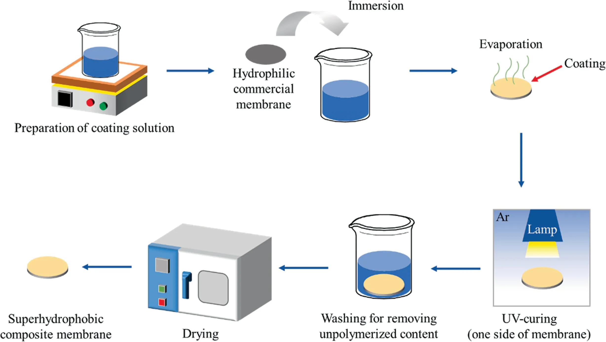
Fig.2. Schematic diagram of the preparation of composite membrane.
2.3.Characterization of membrane
2.3.1.Basic properties of the membrane
Surface and cross-section of membrane samples were stuck onto the special stage and the morphology was observed by field emission scanning electron microscopy (FE-SEM, Hitachi S4800,Japan).An atomic force microscopy (AFM, Bruke Icon, Germany),taping mode, was employed to analyze surface topography of membrane samples in ascan size of 10 μm×10 μm.An energy dispersive spectrometer(EDS)was used to identify the element distribution of a membrane surface with and without coating.Fourier transform infrared spectrometer (FTIR, Nicolet 8700 spectroscopy,Thermo Fisher Scientific Inc., USA) was employed to analyze the presence of some particular groups on membrane surface after modification.The pore size of the obtained membranes was measured based on the principle of gas-liquid exclusion method by a membrane pore size distribution apparatus (PSDA-20, Gaoqian function Co., Nanjing, China).The porosity was measured by a gravimetric method.The mechanical properties (tensile stress and elongation at break)of membranes are tested by a tensile testing instrument (MODEL SH-20, Wenzhou Shandu Instrument Co.,China).The same procedures can be found in our previous work[23].
2.3.2.Measurement of anti-wetting ability
Surface contact angle (CA) and liquid entry pressure of water(LEPw)both are the most significant parameters for the evaluation of hydrophobicity of membranes.Contact angle was measured by the contact angle instrument (DropMeter A-100, MAIST Measurement Co., Ltd., China).A droplet, the volume of which was about 2 μl, was dripped onto the membrane surface; consequently, the condition of the droplet was observed and analyzed by the software.
LEPwindicates the minimum pressure value at which the liquid can penetrate the membrane [24].It can determine the normal operating pressure of a hydrophobic membrane, so as to avoid the risk of membrane wetting due to the high working pressure.Also,the value of LEPwwas related to the pore size and its distribution [25].In this work, it was measured with DI water by a homemade device, as shown in Fig.3.

Fig.3. Schematic diagram of liquid entry pressure of water (LEPw).
All membrane characterization measurements were repeated at least three times for each sample and the corresponding average value and standard deviation were obtained.
2.4.Evaluation of VMD performance
The schematic diagram about the VMD device is shown in Fig.4.The detailed experimental parameters are listed in Table 1.
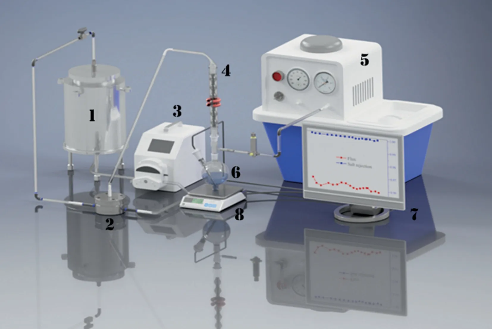
Fig.4. Schematic diagram of VMD setup (1.feed tank, 2.membrane module, 3.peristaltic pump, 4.condenser, 5.vacuum pump, 6.collector, 7.computer, 8.balance).

Table 1The experimental parameters of the VMD system
The permeate flux,Jwas calculated by the following equation:

wheremis the weight of permeate water after an experimental interval timet, andAis the effective membrane surface area.
The salt rejection,R, was calculated by Eq.(3):

where μpand μfare the conductivities of permeate solution and feed solution, respectively.
In addition,the concentration factor(K)of the feed solution for each experiment period was evaluated by:

whereQp(kg)is the cumulative permeate weight,Q0(kg)is the initial weight of feed solution.
3.Results and Discussion
3.1.Membrane morphology
In order to identify the effects of the PFPE on morphology after modification,the SEM images of the surface and cross-section weretested, as shown in Tables 2 and 3.All coated irradiation side of membranes were taken for surface morphology.In general, composite membranes presented the same morphology, sponge pore structure with the original ones.It indicated that the PFPE had not blocked the pore structure of support membranes thoroughly during the coating process.After coating, the surface pores got smaller, especially more obvious for higher coated concentration.Because of the higher concentration,the rate at which the solution flows on the membrane surface and penetrates into the pores of the membrane became slower, the retention of the solution on the membrane surface would be relatively longer.However, the pore size reduction of the 0.45 μm-based membranes did not seem to be obvious.In fact,for all membranes,there were some different degrees of reduction on pore size according to the precise pore sizedata displayed in Section 3.3.For other fact, the coating solution would penetrate more for larger pore size support and exist less on surface.After curing and washing clean, the part on surface was polymerized to be the coating layer, while other would be clean out.At the same time, the polymer (PFPE) that penetrated into membrane would also partially adhere to the inner wall of the membrane, which is a reason for the decrease of membrane pores.In addition, the thickness of all membranes had a slight increasement, which meant there have been a thin coating layer on membrane surface, which also can be observed from crosssection images in Table 3.

Table 4EDX results of 0.22 μm composite membranes with and without UV-curing
3.2.EDX and FTIR results of the composite membranes
EDX and FTIR results of the prepared membranes are shown in Table 4 and Fig.5,respectively.As shown in Table 4,after coating,there was oxygen element distributing on the membrane surface,and there was no trace of oxygen element on the non-irradiated side,proving the success of single-sided modification.More significantly,due to the high fluorination of PFPE,the atomic ratio of fluorine to carbon for the modified membranes was increased to a certain extent compared to the original ones, which is beneficial for the improvement of hydrophobicity.From Fig.5, it is clear to see the difference by the highlighted peaks, points 1 and 2.These highlighted peaks at 1530 and 1730 cm-1, corresponding to the N-H and C=O from the urethanes bands [26], respectively.These two functional groups did not present in the original membranes,which further proved the existence of the PFPE coating layer.
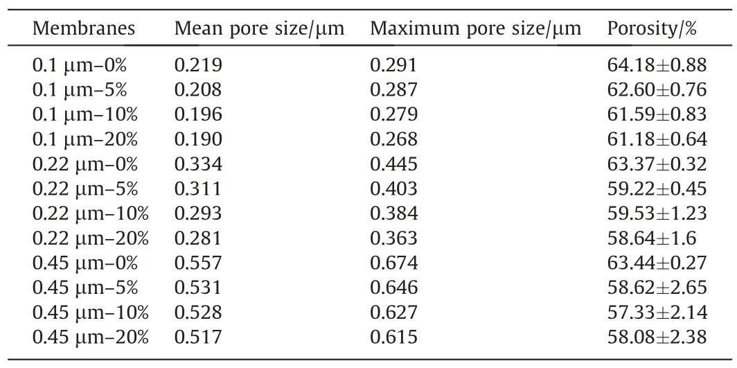
Table 5Pore size and porosity of membrane samples
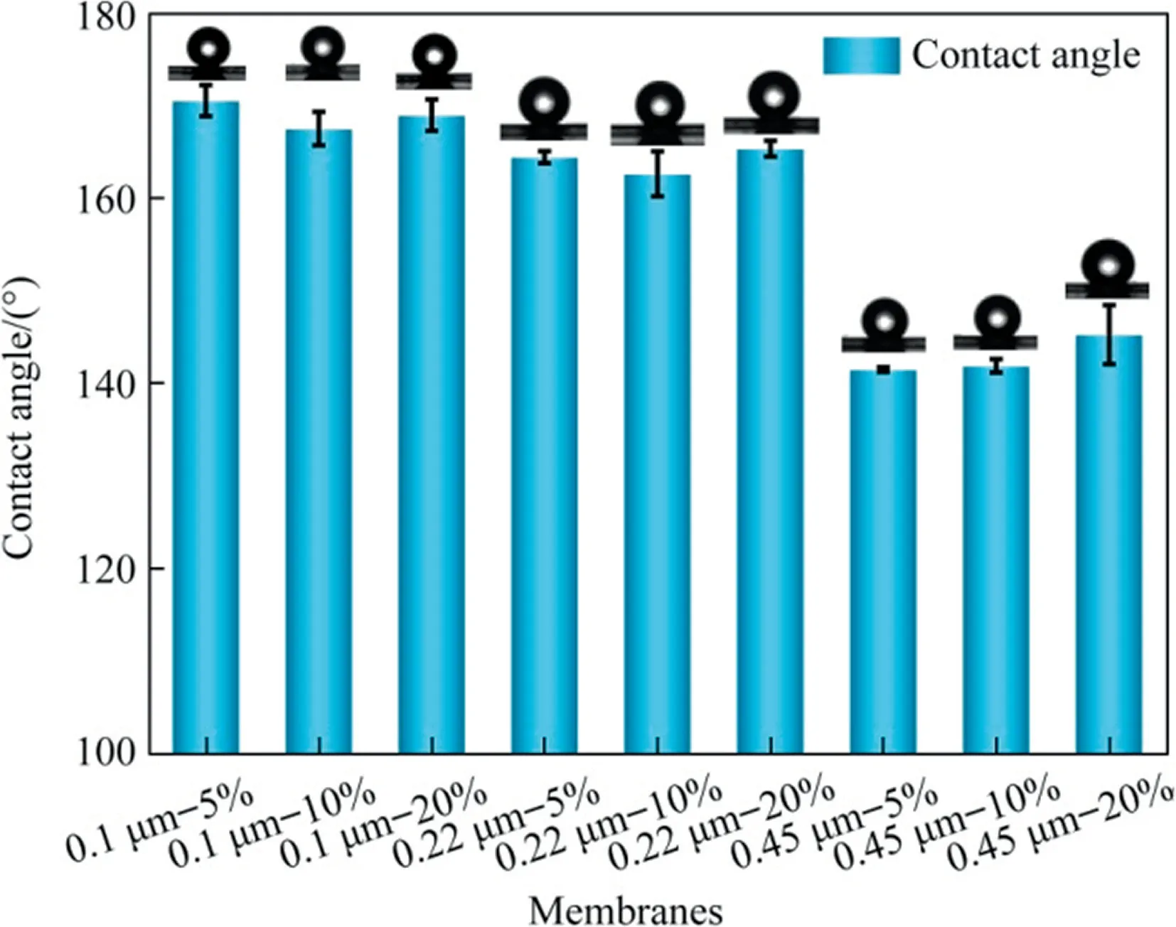
Fig.6. Effects of PFPE concentrations and pore size on contact angle of composite membranes (because of great hydrophilicity of original base membrane — 0%, CA value of which is almost zero).
3.3.Porosity, pore size and its distribution
The pore size of the original PVDF membranes and composite ones is shown in Table 5.The pore size of each membrane sample presented a downward trend, but not very notable except for the 0.45 μm membranes.These results indicated that the pore size and structure of the pristine membranes were not significantly influenced by the presence of the coated layer and the penetration of the polymer solution, which just modified the membrane’s surface without blocking the membrane pores.Only for the large pore size ones, the more coating solution left inside to make the inner structure denser than before, which can be observed from Tables 2 and 3.The porosity of the original and composite PVDF membranes is also shown in Table 5.Comparing with the original PVDF membrane, the porosity of the composite membranes decreased slightly.However,overall,the porosity of all modified membranes was around 60%, which also can be employed in the MD process.
3.4.Anti-wetting ability of the membranes
3.4.1.Contact angle and topography of membrane surface
The contact angle measurements can intuitively reflect the hydrophobicity of membrane surface.Because of the hydrophilic supporting membranes, it can be clearly seen from Fig.6, after modification, especially for 0.1 and 0.22 μm membranes, there was an outstanding improvement on the contact angle.The maximum CA value can reach 170.5°, which can also indicate the existence of the PFPE copolymers.It is worth noting that the droplets can roll freely on the membrane surface (sliding angle ≈0), meaning that the composite membranes are super hydrophobic.In addition, after coating, the CA of modified membranes were all above 140°.With respect to other PFPEs material, the functional group of Fluorolink®AD1700 consisted of tetrafunctional urethane acrylate, which is responsible for the high hydrophobicity of prepared modified membranes [27].Considering the combined effect of the pore size, the increasing of pore size took a negative effect on the CA of membranes.It is easier for the coating solution to penetrate into bigger pores, especially for the lower concentration with the relatively low viscosity.As a result,relatively less coating solution was left onto the membrane surface, and the effect of UV curing was not as good as the smaller pores.
The dynamic CA measurements were also conducted in order to investigate the uniform and stability of the coated layer, as shown in Fig.7.For this part, multiple samples were selected for testing.From Fig.7(a), the supporting PVDF substrate presented high hydrophilicity, this is proved by the fact that the droplets could spread rapidly on the surface of the membrane after few seconds.In comparison,Fig.7(b)shows that after the drop dripped onto the coated membrane surface (irradiated side), the droplets hardly deformed, and the tested CA value kept stable at 162° for a longer time.Simultaneously, samples from different locations on the membranes were taken for this test.All results presented the same tendency, which meant that the coating layer was uniform onto the membrane surface.Except that,Fig.7(c),the CA measurements of the non-irradiated side,figured out the difference between both sides of composite membranes.Though the CA value was greater than 90° at the beginning, it began to decrease and eventually reached zero during the period of test time.It clearly illustrated that the non-irradiated side without curing still preserves the hydrophilic support nature.Except that, different surface tension liquids (water, 30% (volume) ethanol, 0.4 mmol·L-1SDS and mineral oil)were used to measure the contact angle of modified membrane,compared with the commercial membrane,shown in Fig.S1.
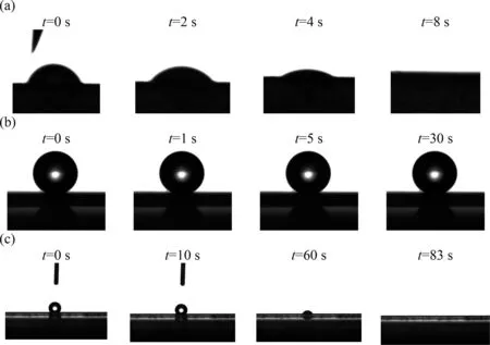
Fig.7. Stability of contact angle for different membranes during test period: (a) commercial PVDF membranes (0.22 μm), (b) composite PVDF membranes (0.22 μm-10%,irradiated side), (c) composite PVDF membranes (0.22 μm-10%, non-irradiated side).
Regardless of the Young’s equation, the Wenzel’s equation or others [28], both explained that the contact angle of membrane would be affected by the roughness of membrane surface.The hierarchical surface structure would be formed onto the surface with higher roughness value, and air would be trapped inside it to constitute a gas-liquid interface[29].Finally,higher contact angle values would be obtained.For the hydrophobic surface, the contact angle usually tends to be higher with the rougher surface.Therefore, AFM was used to characterize the changes in the surface topography of the coated membranes after modification.The indexes,including the mean roughness(Ra)and maximum surface roughness (Rmax) noted in Table 6, were used to evaluate the surface roughness of membranes.
The 3D imagesin Table 6 show the corresponding topography of the original and coated 0.22 μm membranes.According to the data shown in Table 6, after modification, the roughness of composite ones presented higher roughness values; while the nonirradiated side exhibited a similar value with the original membranes.Combined with topography images in Table 6, the images demonstrated the existence of the coating layer.The polymer coated on the membrane surface coagulated and formed protrusions after UV-curing,thereby changing membrane surface roughness, which can be seen clearly between the modified and unmodified ones.From Table S1,shown in supplementary file,only for 0.45 μm membranes, small variations in the surface roughness values were observed.This could be explained by the larger size of pores of the supporting membrane which caused an increase in the amount of coating solution penetrating into pores, and hence reduced the influence on membrane surface roughness.This is precisely one of the reasons for the low contact angle value of the 0.45 μm membrane sample.In all, the changing trend of membrane surface roughness kept consistent with that of the contact angle in Fig.5.More details and data are listed in Table S1 and Fig.S2.
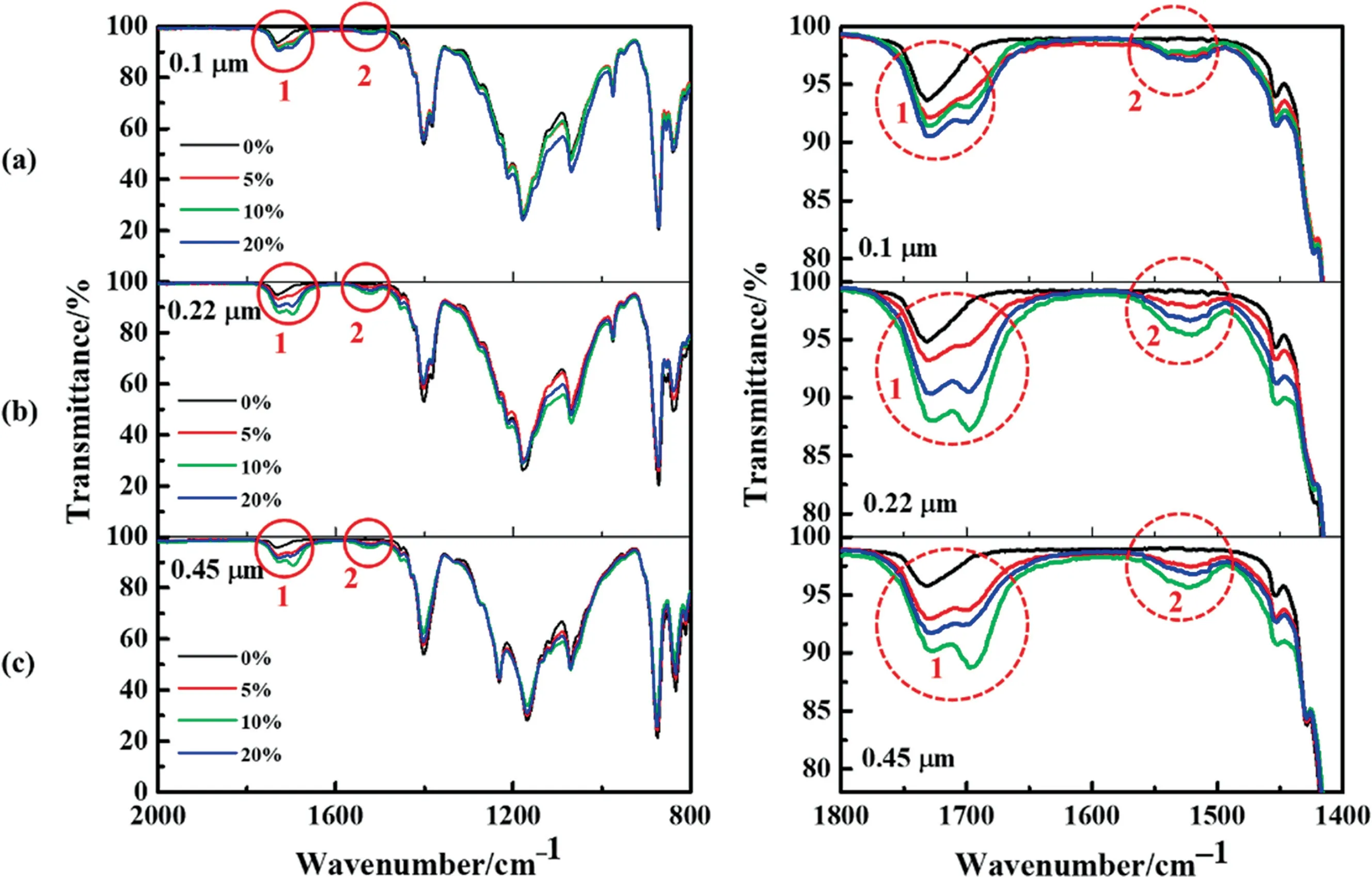
Fig.5. FTIR spectra of different pore size composite membranes coated by different mass concentrations: (a) 0.1 μm PVDF membranes, (b) 0.22 μm PVDF membranes, (c)0.45 μm PVDF membranes.

Table 6Surface roughness values and 3D images of membranes with and without UV-curing
3.4.2.Liquid entry pressure of water (LEPw)
LEPwreflects the minimum value of the pressure, under which the water would enter the hydrophobic membrane pores duringoperation.This pressure depends on the maximum pore size of membranes and the hydrophobicity of membrane materials and modified materials[14].In VMD,the LEPwof the membrane should be higher than the extra pressure on permeation,or the membrane would be wetted by feed solution easily.The LEPwcould be calculated based on the Young-Laplace equation [30,31],

whereBis the dimensionless geometric factor which can be equal to 1 for assumed perfectly cylindrical pores,γLis the liquid surface tension,θ is the CA in degrees,andrmaxis the maximum pore size.A higher LEPwwould be obtained by the higher CA and the smaller pores.The data about all LEPwvalues are shown in Fig.8.The figure shows as,expected,the highest LEPwvalue was obtained for 0.1 μm,and it increased with the PFPE contents.The LEPwvalues of 0.1 and 0.22 μm composite membranes were above 0.3 MPa, while the 0.45 μm ones have kept a relatively low level in the range of 0.1-0.15 MPa.
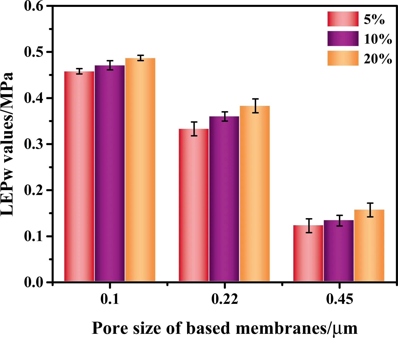
Fig.8. Effects of PFPE mass concentrations and pore size on LEPw values for composite membranes.
3.5.Mechanical properties

Fig.11. Separation performance of 0.22 μm-5%composite membranes in VMD:(a)the permeate flux and salt rejection rate for a relative long period,(b)change of permeate flux with concentration factor during whole process.(Test conditions: feed solution concentration 35 g·L-1 NaCl, feed temperature: 60 °, flow rate of circulated feed solution:800 ml·min-1, permeate side pressure (vacuum): 0.095 MPa).
Mechanical property is another non-negligible parameter for membranes, especially for VMD operation.The data about mechanical properties (tensile stress and elongation at break) is shown in Fig.9.In MD process, there always exists a pressure difference between both sides of membranes, which requires the membrane to have a specific strength and elasticity.It could be found that the coating of PFPE influenced the membrane mechanical properties.During the coating process, PFPE worked as a linking agent, improving the cohesion of the PVDF particles and the joint strength between membrane channels.Therefore, before being broken, the coated membranes would afford higher power than the original ones.Since the membrane structure did not change significantly, which has been reflected by the pore size measurement, the stretch ability of the membrane is relatively dependent on the membrane material, so there is just a little change in the elongation of the membranes.
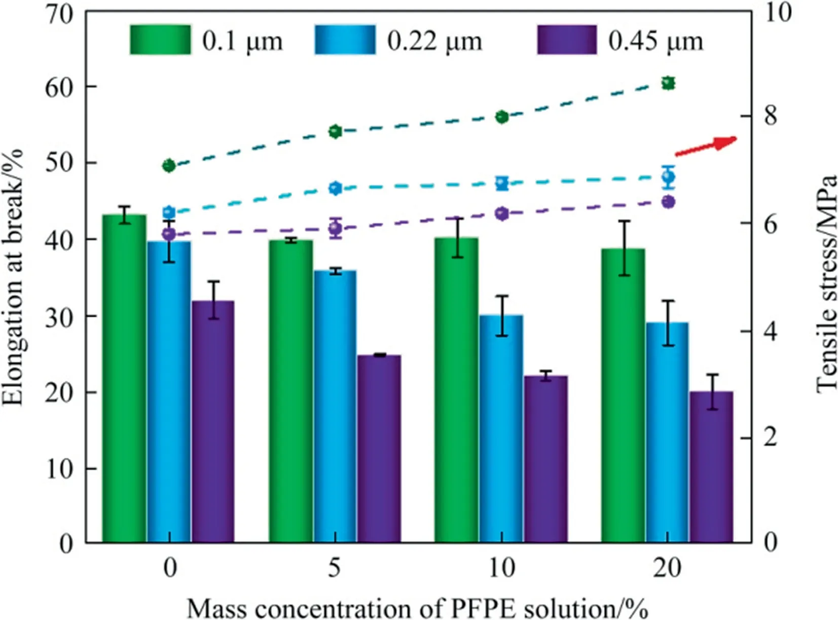
Fig.9. Effects of PFPE mass concentrations and pore size on mechanical properties of composite membranes.
3.6.Operation performance in VMD
The VMD experiments were carried out using 3.5%(mass)saline NaCl feed solution as feed to characterize the separation and permeation performance of prepared composite membranes.The irradiated side of the membrane was made in direct contact with the hot feed at a temperature of 60 °C.The permeability of different pore size composite membranes is shown in Fig.10.Obviously,the maximum VMD flux of 37.53 kg·m-2·h-1corresponded to composite membranes with the largest pore size-0.45 μm and 5%PFPE mass concentrations.The flux decreased with increasing coating concentration.This tendency was consistent with the variation of membrane pore size,which has been described in Section 3.4.Taking the porosity into consideration, it has been found that the porosity did not affect the performance characteristics for all composite membranes.For VMD tests in this work, where Knudsen flow dominates [32], the MD permeate flux can be considered directly proportional to pore size, indicating that the larger transferring channels and lower mass transfer resistance would be created for large pore size membranes.However,during the operation period, the 0.45 μm composite membranes were wetted in a relatively short time,about 2 h,and the conductivity value detected on the permeate side was high.The lower values of contact angle and LEPwfor the 0.45 μm composite membranes resulted in lower antiwetting properties.However,due to the excessive amount of coating solution entering the membrane pores, the UV-cured surface was poorly hydrophobic.All other membranes can maintain a salt rejection rate of more than 99.99%.
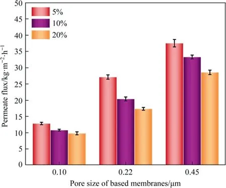
Fig.10. Effects of PFPE mass concentrations and pore size on VMD permeate flux of different composite membranes (Test conditions: feed solution concentration 35 g·L-1 NaCl, feed temperature: 60°C, flow rate of circulated feed solution:800 ml·min-1, permeate side pressure (vacuum): 0.095 MPa).
Owing to the homogenous pore structure, excellent hydrophobicity, and high permeate MD flux, the 0.22 μm-5% membranes were chosen to carry out the MD stability experiments.The coating layer, being having hydrophobicity nature kept the flux relatively stable, with only a slight decrease after 25 h of operation from 29.08 to 23.21 kg·m-2·h-1as shown in Fig.11(a).This decrease may be caused by the increase of feed solution concentration during the MD process,which reduced water activity and the vapor pressure on the feed side.Thereby, the mass transfer driving force was decreased, and the obtained permeate flux was reduced [33].Fig.11(b), indicates that after 25 h of VMD operation, the flux though dropped to 23.21 kg·m-2·h-1,the corresponding concentration factor of the MD system reached a value of 4.08(about 14.28%(mass) NaCl) and kept stable salt rejection over 99.99%.Therefore,the PFPE coated, composite membranes showed a great potential for desalination because of the excellent hydrophobicity of PFPE.
4.Conclusions
Hydrophobic/hydrophilic PFPE/PVDF composite membranes were fabricated by dip-coating,followed by the UVin situpolymerization.The effects of supporting PVDF substrate membrane pore sizes and concentration of PFPE as a coating material were investigated.All experimental results have shown that the coating layer has been successfully cured onto a supporting substrate membrane surface without changing the original porous structure.More significantly, the coating layer drastically increased the anti-wetting properties.The contact angle and LEPwof all membranes based on 0.1 and 0.22 μm PVDF membranes exceeded 160° and 0.3 MPa,respectively.As for those based on 0.45 μm, the highest CA value reached 145.2°.These results are all suitable for the VMD process.Though the membrane porosity had slightly decreased in comparison to the pristine membrane as caused by the partial penetration of coating solution into the membrane, all porosity values were within the suitable range for MD.At the same time,the mean pore diameter of the modified composite membrane was not influenced greatly after coating and UV-curing.The thickness of the thin hydrophobic coating layer was not clearly visible in SEM images.VMD tests demonstrated good performance of membranes and stability of the coating.The MD flux was positively affected by increasing support pore size while the influence of coated PFPE content was opposite.Regarding stability tests carried out with 3.5%(mass)NaCl solution as feed at 60 °C, 0.22 μm-5% composite membranes was chosen to conduct.During the period, a high stable rejection(99.99%after 25 h of operation)and permeate flux of 29.08 kg·m-2-·h-1was obtained.The stability of these membranes proves its promising potential for desalination applications.
Declaration of Competing Interest
The authors declare that they have no known competing financial interests or personal relationships that could have appeared to influence the work reported in this paper.
Acknowledgements
The authors would like to express their appreciation for the financial support of the National Key Research&Development Program of China (2017YFC0403702), the National Natural Science Foundation of China(51861135203),the Jiangsu Provincial Department of Human Resources and Social Security (JNHB-036), the Materials-Oriented Chemical Engineering State Key Laboratory Program (KL19-04).The authors also extend their appreciation to the Deputyship for Research and Innovation,Ministry of Education in Saudi Arabia for funding this research work through the project number (632).
Supplementary Material
Supplementary data to this article can be found online at https://doi.org/10.1016/j.cjche.2021.03.018.
 Chinese Journal of Chemical Engineering2022年5期
- Chinese Journal of Chemical Engineering的其它文章
- Notes for Contributors
- Solubility determination and thermodynamic modeling of bis-2-hydroxyethyl terephthalate (BHET) in different solvents
- Insights into the cross-amyloid aggregation of Aβ40 and its N-terminal truncated peptide Aβ11-40 affected by epigallocatechin gallate
- Numerical study on hydrodynamic characteristics of spherical bubble contaminated by surfactants under higher Reynolds numbers
- Spray-drying assisted layer-structured H2TiO3 ion sieve synthesis and lithium adsorption performance
- Fabrication and characterization of hierarchical porous Ni2+ doped hydroxyapatite microspheres and their enhanced protein adsorption capacity
