
Bismuth chloride@mesocellular carbon foam nanocomposite cathode materials for rechargeable chloride ion batteries
2022-06-20 06:22ChngZhngShijioSunMeifenWuXingyuZho
Chinese Chemical Letters 2022年4期
Chng Zhng,Shijio Sun,*,Meifen Wu,Xingyu Zho,c,*
a College of Materials Science and Engineering,Nanjing Tech University,Nanjing 211816,China
b CAS Key Laboratory of Materials for Energy Conversion,Shanghai Institute of Ceramics,Chinese Academy of Sciences,Shanghai 200050,China
c Jiangsu Collaborative Innovation Center for Advanced Inorganic Functional Composites,Nanjing Tech University,Nanjing 211816,China
ABSTRACT Chloride ion batteries(CIB)are considered to be one of the most promising energy storage devices.As cathode materials for CIBs,metal chlorides have many advantages,such as high theoretical energy density,abundant elemental resources and ideal discharge voltage plateau.However,the dissolution and huge volume change of metal chlorides during cycling lead to considerable short lifespan,which limits their potential application for CIBs.Herein,the bismuth chloride nanocrystal is confined in mesocellular carbon foam matrix by a new vacuum impregnation approach.The mesocellular carbon foam with large interconnected pores(15.7 or 23.2 nm)may buffer the large volume variation of bismuth chloride during charge and discharge,giving rise to significantly enhanced electrochemical performance.The as-prepared bismuth chloride@mesocellular carbon foam cathode delivered an initial discharge capacity of 298 mAh/g and a reversible capacity of 91 mAh/g after 60 cycles.In contrast,the pure bismuth chloride cathode almost cannot discharge after 30 cycles.This is the first report that the metal chloride cathode can achieve a prolonged cycling in CIBs.
Keywords:Chloride ion batteries Cathode materials Bismuth chloride Mesocellular carbon foam Electrochemistry
Chloride ion batteries(CIB)based on the transfer of chloride ion have attracted significant attention because of their high theoretical volumetric energy density(2500 Wh/L)and abundant material resources[1–3].In the first concept,this battery system employed commercial metal chloride(CoCl2,VCl3or BiCl3)as the cathode,lithium metal as the anode and a binary ionic liquid as the electrolyte.However,severe capacity decay occurs during cycling,which is caused by dissolution of metal chloride into the electrolyteviaLewis acid/base interaction and/or the large volume contraction/expansion of metal chloride upon cycling[4,5].Subsequently,metal oxychlorides including BiOCl[6],FeOCl[6,7]and VOCl[8,9]with good chemical stability in the electrolyte were explored as cathode materials for CIBs.Nevertheless,metal oxychlorides also suffered from a large volume change during repeated charge and discharge,resulting in pulverization and electrical disconnection between active material particles[10,11].An effective strategy is to incorporate different carbon materials(e.g.,carbon nanotube,carbon black,graphene nanoplatelets and ordered mesoporous carbon CMK-3)[12,13]or conducting polymers[14,15]into metal oxychloride cathodes.Recently,layered double hydroxides(Ni2V0.9Al0.1-Cl[16],CoFe-Cl[17],NiMn-Cl[18],NiFe-Cl[19])were demonstrated to be effective intercalation cathode materials for CIBs due to their good chemical and structural stability.Besides inorganic electrode materials,chloride ion-doped polypyrrole[20]and polyaniline[21]have also been developed as cathode materials for chloride ion batteries.The polymer cathode materials exhibit reversible electrochemical energy storage based on the redox reactions of nitrogen species and chloride ion transfer.Although some progresses have been achieved,the research of CIBs is still at an early stage[22].Exploiting alternative cathode materialsviadesigning new materials or modifying the current materials with high capacity and long lifetime is highly desired.
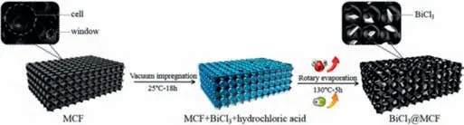
Fig.1.Schematic representation of the preparation of BiCl3@MCF.
As mentioned above,even though the feasibility of transitionmetal chlorides to be cathode materials has been proved,they showed inferior electrochemical activity.For example,commercial BiCl3delivered an initial discharge capacity of 142.9 and~75 mAh/g after only 3 cycles even at a low current density of 3 mA/g.Considering the insoluble behavior of BiCl3in the electrolyte,the authors attributed this capacity decay to the large volume change of the conversion reaction between Bi metal and BiCl3[1].Inspired by the carbon incorporation effect for the FeOCl cathode material in CIBs,it is possible to improve the chloride-ion storage performance of BiCl3using the similar strategy[12,13,23].However,it is difficult to obtain BiCl3/carbon nanocomposite because BiCl3is highly hygroscopic in air to irreversibly form BiOCl[24].Therefore,the reports on preparation of BiCl3/carbon nanocomposites are rare.To our best knowledge,the only work was reported by Anumolet al.who heated the mixture of BiCl3and MWCNTs in a sealed quartz ampule under vacuum to obtain the BiCl3@multi-walled carbon nanotube(BiCl3@MWCNT)nanocomposite[25].In order to melt BiCl3into a liquid state,a high reaction temperature of 500 K needs to be used.A long heating time of more than 72 h is also required to infiltrate the molten BiCl3into the carbon nanotube because of the high surface tension and viscosity of molten BiCl3.Therefore,this preparation process is energy-and time-consuming.Furthermore,the purity of the final product depends strictly on the tightness of the preparation system and the purity of the BiCl3raw material since BiCl3is easily transformed into BiOCl upon exposure to air.
In this study,a facile and novel strategy is developed to prepare BiCl3@mesocellular carbon foam(BiCl3@MCF)nanocomposite for CIBs.The commercial BiCl3dissolved in hydrochloric acid is successfully loaded into the MCF with open porous structure at a considerably mild condition(298 K for 18 h and 393 K for 5 h)viaan infiltration process.The hydrochloric acid medium can inhibit the hydrolysis of BiCl3[26–29].When assembled into CIBs,the BiCl3@MCF nanocomposite electrode exhibited significantly enhanced electrochemical properties compared to the BiCl3electrode,such as an initial discharge capacity of 298 mAh/g and a reversible capacity of 91 mAh/g after 60 cycles.The superior electrochemical performance is attributed to the unique BiCl3@MCF electrode architecture.BiCl3nanocrystals with a size less than 10 nm are favorable for the rapid transport of electrons and Cl–[30–32].The porous carbon scaffold could facilitate electrolyte penetration and provide a mechanical cushion to buffer the large volume variation of BiCl3during repeated charge and discharge.This is the first report that the metal chloride cathode can achieve a prolonged cycling in CIBs.
Two kinds of mesocellular carbon foams(MCF-1 and MCF-2)with different porosities were preparedviaa nano casting method with the Al-impregnated mesocellular silica foams as hard templates.The detailed fabrication process is provided in Supporting information.The scheme of the fabrication process for the BiCl3@MCF composites is shown in Fig.1.First,1 g of commercial BiCl3was dissolved in 1 mL of concentrated hydrochloric acid.Then,the solution was impregnated into 0.5 g of the mesocellular carbon foam obtained above at 298 K under vacuum for 18 h.The obtained paste was dried by rotary evaporation at 393 K for 5 h to remove hydrochloric acid.The as-prepared powders were denoted as BiCl3@MCF-1 and BiCl3@MCF-2 when MCF-1 and MCF-2 were used as carbon matrix,respectively.Likewise,the commercial BiCl3powder was treated in the same way except the use of MCF to form a BiCl3electrode material.
Electrochemical measurements were conducted using coin cells(CR2032).The anode was lithium metal(Alfa Aesar).The separator is glass fiber film(Whatman).The working electrode was prepared by pressing a mixture of 80 wt% BiCl3@MCF nanocomposite or BiCl3,10 wt% carbon black and 10 wt% PVDF powders between two stainless steel meshes.The loading weight of the as-prepared composite material in the cathode is about 1.5 mg.The 0.5 mol/L PP14Cl in PP14TFSI was used as the electrolyte[7].The galvanostatic discharge and charge was tested on a Neware battery testing system(Neware Co.,Ltd.).Cyclic voltammetry(CV)and electrochemical impedance spectroscopy(EIS)were measured on a BioLogic(VMP3)battery testing system.All electrochemical measurements were performed at 298 K.
The wide-angle XRD patterns of the two mesocellular carbon foams(Fig.S1a in Supporting information)show two broad peaks at 23.8°and 43.6°,corresponding to the(002)and(100)planes of graphite,respectively.Small-angle XRD patterns of the MCF-1 and MCF-2(Fig.S1b in Supporting information)both exhibit one welldefined diffraction peak,implying the ordered mesoporous structure of the as-prepared carbon materials.This regular and ordered mesostructure is beneficial to achieve homogeneous distribution of BiCl3nanocrystals and prevent its aggregation in the carbon matrix.The porosity of the as-prepared MCFs was investigated by nitrogen adsorption/desorption analysis.The isotherms of MCF-1 and MCF-2 exhibit the type-IV shape with two H2-type hysteresis loops at medium and high relative pressures,indicating the presence of the small mesopores with size of around 3 nm inside the walls of the MCFs and the large cellular mesopores,respectively(Fig.S2 in Supporting information).The cell and window size of the MCFs(inset in Fig.S2)were calculated from the adsorption and desorption branch of the isotherm using the Barrett-Joyner-Halenda(BJH)method,respectively.The textural parameters including total pore volume,cell diameter,window diameter and Brunauer-Emmett-Teller(BET)specific surface area of the mesocellular carbon foams were summarized in Table S1.By increasing the amount of organic swelling agent 1,3,5-trimethylbenzene(TMB)from 1.2 g to 6 g,the total pore volume,cell and window diameter increase from 1.5 cm3/g,15.7 nm and 15.2 nm for MCF-1 to 2.0 cm3/g,23.2 nm and 22.3 nm for MCF-2,respectively.The BET specific surface area decreases from 1429 m²/g for MCF-1 to 993 m²/g for MCF-2.The large pore size and pore volume of the mesocellular carbon foams may be suitable for accommodating a large amount of electroactive BiCl3material.The interconnected mesoporous structure of the mesocellular carbon foams could facilitate the rapid release of water vapor during heating the BiCl3·HCl·H2O system,thus avoiding the appearance of BiOCl impurity during the sample preparation process.
Fig.S3(Supporting information)shows the SEM images of the as-prepared MCFs.The low-magnification images(Figs.S3a and c)show that the MCFs comprise irregular micrometer sized particles.Upon considerably enhanced magnification,that the MCF particle is composed of nanospheres with a size of ~20 nm.The assembly of the nanospheres generates a highly porous structure.The corresponding energy-dispersive X-ray spectra(EDS)reveal an extremely low content of Si element and the absence of Al element,indicating that the Al-impregnated mesocellular silica foam templates have been almost completely removed.To further study the structure and morphology of the as-prepared mesocellular carbon foams,transition electron microscopy(TEM)and the corresponding selected area electron diffraction(SAED)were performed(Fig.S4 in Supporting information).The MCFs show a typical honeycombed structure(Figs.S4a and c)and the pore sizes of 16 nm for MCF-1 and 23 nm for MCF-2,which are consistent with the above N2physisorption results.The corresponding SAED patterns(Figs.S4b and d)of the MCFs display blurred diffraction rings,revealing the nanocrystalline structure that is consistent with the above wideangle XRD results.
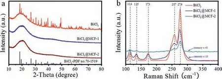
Fig.2.(a)Wide-angle XRD pattern and(b)Raman spectra of BiCl3 and BiCl3@MCFs.
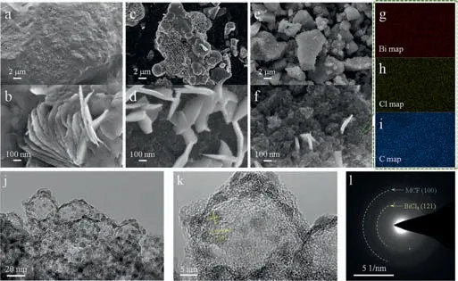
Fig.3.FE-SEM images of(a,b)BiCl3,(c,d)BiCl3@MCF-1 and(e,f)BiCl3@MCF-2.(g–i)The corresponding elemental mapping images of BiCl3@MCF-2;(j,k)TEM images and the corresponding(l)SAED of BiCl3@MCF-2.
Fig.2a shows the XRD patterns of the as-prepared BiCl3and BiCl3@MCFs nanocomposites.The broad background centered at about 20.0°is ascribed to the amorphous 3M tape used for preventing the samples from moisture absorption during the tests.The diffraction peaks of the BiCl3sample coincides well with that of the orthorhombic BiCl3phase(PDF card No.70–1519),demonstrating that the acidic treatment of the commercial BiCl3did not introduce any impurities.The XRD patterns of BiCl3@MCF-1 and BiCl3@MCF-2 only display the broad peak of the 3M tape and no characteristic peaks of BiCl3were detected,which may be due to the poor crystallinity of BiCl3caused by the confined growth inside pores of the MCFs.Raman spectroscopy was further conducted to analyze the phase structures of the asprepared BiCl3@MCFs(Fig.2b).The samples were sealed between two pieces of glasses to prevent moisture contamination.Five characteristic peaks are identified in the Raman spectrum of the BiCl3sample[33–35].Similar Raman signals are detected for the BiCl3@MCF nanocomposites,confirming the presence of BiCl3in the as-prepared BiCl3@MCF nanocomposites.The decreased intensity of Raman peaks for the BiCl3@MCF nanocomposites may be due to the encapsulation of the BiCl3phase inside the pores of MCFs[36].
In order to study the morphology of the BiCl3@MCF nanocomposites,field-emission scanning electron microscopy(FE-SEM)was performed.From Figs.3a and b,it can be seen that the BiCl3sample is consisted of agglomerated nanosheets,with a thickness of about 20 nm.Figs.3c–f present the morphologies of the BiCl3@MCF-1 and BiCl3@MCF-2 composites at two different magnifications.By comparing Figs.3d and f with Figs.S3b and d,it is clear that the apparent morphology of mesocellular carbon foams is retained for both BiCl3@MCF composites.For the BiCl3@MCF-1 sample,there are large amount of bare BiCl3nanosheets attached on the surface of the carbon matrix MCF-1.In contrast,much fewer BiCl3nanosheets are observed for the BiCl3@MCF-2 sample,indicating that most of the BiCl3particles are encapsulated into the carbon matrix MCF-2.This is because the carbon matrix MCF-2 with a larger pore volume,larger cell and window diameter can accommodate more BiCl3.The corresponding elemental mapping images(Figs.3g–i)further show that the Bi and Cl elements are evenly distributed in the carbon matrix,indicating that BiCl3nanoparticles are uniformly distributed in the mesocellular carbon foam matrix.
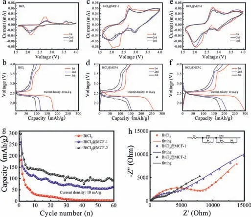
Fig.4.CV and discharge-charge curves of(a,b)BiCl3(c,d)BiCl3@MCF-1 and(e,f)BiCl3@MCF-2.(g)Cycling performance and(h)nyquist plots of BiCl3 and BiCl3@MCFs.
In order to further confirm the phase purity of the BiCl3@MCF-2 composite,transition electron microscopy and the corresponding selected area electron diffraction(SAED)were carried out.Fig.3j indicates that the porous structure of MCF-2 can be maintained after loading of BiCl3.The high-resolution transmission electron microscopy image of the BiCl3@MCF-2 composite(Fig.3k)shows that many crystalline particles with size less than 10 nm are homogeneously distributed in the amorphous carbon matrix MCF-2.The interplanar spacing of 0.306 nm is well matched with the d spacing of the(211)lattice plane of BiCl3.The corresponding SAED pattern(Fig.3l)shows that besides the blurred diffraction ring corresponding to(100)plane of the carbon matrix,the dispersed diffraction ring with the interplanar spacing of 0.334 nm agrees well with(121)plane of the BiCl3phase.Hence,the TEM result further verified the confinement of pure BiCl3nanocrystal in the mesocellular carbon foams.
In the following,we investigated the electrochemical performances of the as-prepared BiCl3,BiCl3@MCF-1 and BiCl3@MCF-2 materials.Cyclic voltammetry(CV)tests were recorded at a scan rate of 0.05 mV/s with a potential range of 1.6–4 V.The CV curves of the BiCl3and the BiCl3@MCF cathodes(Figs.4a,c and e)all show one major couple of redox peaks and two weak couples of redox peaks.This implies a three-step electrochemical reaction between BiCl3and Bi metal,consistent with the commercial BiCl3reported previously[1].Galvanostatic dischargecharge tests were carried out at a current density of 10 mA/g.Figs.4b,d and f illustrate the first three charge-discharge profiles of the three cathodes.In accordance with the CV results,one major charge/discharge plateau in the vicinity of 2.5 V accompanying with two short charge/discharge plateaus are observed.Benefitted from the nanoconfinement effect of the BiCl3nanoparticles within the mesocellular carbon foams,the BiCl3@MCF nanocomposites show higher utilization of active materials than the BiCl3sample.The initial discharge capacities for the BiCl3@MCF-2 and BiCl3@MCF-1 cathodes are 298 mAh/g and 261 mAh/g,respectively,much higher than 182 mAh/g for the BiCl3cathode.Fig.4g presents the cycling performance of the three cathodes.For the two nanocomposite cathodes,they display high reversible capacities of 91 mAh/g(BiCl3@MCF-2)and 60 mAh/g(BiCl3@MCF-1)after 60 cycles.On the contrary,the BiCl3cathode remains little capacity after 30 cycles.The terrible capacity retention of the BiCl3cathode is likely originated from structural collapse of the electrode and the loss of electrical contact with the current collector because of the large volume changes of BiCl3during repeated charge and discharge.The excellent cycling performance of the BiCl3@MCF nanocomposite cathodes can be attributed to the enhanced structural stability by encapsulation of BiCl3into mesocellular carbon foams[37].Moreover,a high energy density of 2097 Wh/L can be reached in this work,which is close to the theoretical volumetric energy density(2500 Wh/L).Besides,the energy-dispersive X-ray analysis(Fig.S5 in Supporting information)on glass fiber separator(the side facing lithium metal)after 70 cycles reveals the absence of Bi,Fe,Cr and Ni elements,indicating BiCl3was not dissolved in the electrolyte and the stainless steel collector was not corroded during cycling.Hence,unlike the other metal chlorides such as CoCl2and VCl3,the dissolution of BiCl3in the electrolyte can be ignored.
To further elucidate the different electrochemical properties of the BiCl3and BiCl3@MCF composites,electrochemical impedance spectroscopy(EIS)tests were performed.The EIS curves consist of two parts,a broad arc at high and medium frequency and a straight line at low frequency(Fig.4h).The broad arc at high and medium frequency represents the combined contribution of the contact resistance(Rc)and the charge transfer process(Rct).The straight line at low frequency may be related to the Warburg resistance reflecting the solid-state diffusion of chloride ions in the bulk electrode[38,39].The EIS plots can be well fitted according to the equivalent circuit model shown in the inset of Fig.4h.The fitted electrochemical kinetic parameters of the BiCl3and BiCl3@MCF cathodes are shown in Table S2(Supporting information).The BiCl3@MCF-2 cathode(96 Ohm)possesses a smaller charge transfer resistance than the BiCl3@MCF-1(167 Ohm)cathode,which could be attributed to less exposed BiCl3nanosheets on the surface of the MCF matrix.Moreover,the charge transfer resistances of the BiCl3@MCF-1 and BiCl3@MCF-2 cathodes are much smaller than that of the BiCl3cathode(2431 Ohm).Therefore,the unique BiCl3@MCF composite architecture can considerably enhance the electrical conductivity and charge transfer of the corresponding electrode.
In order to understand the electrochemical reaction mechanism of the BiCl3@MCF-2 cathode,the batteries after initial discharge and charge were disassembled.The cycled cathodes were directly characterized by XRD as shown in Fig.S6a(Supporting information).The Bi metal(PDF card No.2–518)formed after the 1stdischarge as indicated by the arrows in Fig.S6a,revealing a conversion reaction mechanism which is consistent with the previous report[1].After the 1stcharge,the Bi phase disappeared,the BiCl3phase was nevertheless not detected.The weak peaks of the BiCl3nanocrystals even if formed after the 1stcharge could be overlapped by the broad peak of the 3M tape.Becauseex-situXRD cannot prove the recovering of BiCl3phase after the 1stcharge,FESEM and the corresponding EDS(Figs.S6b and c)were used to further clarify whether chloride ion was back or not after the 1stcharge.In order to avoid the interference of Cl–in the electrolyte,solvent of the electrolyte(PP14TFSI)was used to wash the electrode disks detached from the current collector.The corresponding EDS results(Fig.S6b inset)verify the removal of chloride ions from the BiCl3@MCF-2 cathode after the 1stdischarge as the atomic ratio of Cl element to Bi element is around 0.56.After the 1stcharge,the increased atomic ratio between Cl element and Bi element to around 2.5 further confirmed shuttle back of chloride ions to the BiCl3@MCF-2 cathode.Raman spectroscopy was further used to investigate the structural evolution of the BiCl3@MCF-1(Fig.S7 in Supporting information)cathode during the 1stdischarge and charge process.The two peaks at 50–80 cm-1in Raman spectrum of the pristine electrode after rest for 20 h can be assigned to BiCl3[40].Compared with Fig.2b,the absence of other peaks is probably due to the formation of complex ion(such as BiCl52-or BiCl63-)between BiCl3and the electrolyte[41].A broad peak at 80–105 cm-1appeared after the 1stdischarge,which can be assigned to Bi metal[36,42],this broad peak disappeared after the subsequent charge,further suggesting the extraction/insertion of chloride ions from/into the BiCl3@MCF composite materials.
In summary,we reported the BiCl3@MCF nanocomposite material for chloride ion batteries which was prepared by vacuum impregnation and subsequent rotary evaporation at 393 K for 5 h,and achieved stable cycling performance of metal chloride for the first time.X-ray diffraction and Raman spectroscopy revealed the high purity of the BiCl3@MCF nanocomposite.Field-emission scanning electron microscopy and transition electron microscopy revealed that most of the BiCl3nanocrystals with size less than 10 nm were uniformly encapsulated into the pores of the mesocellular carbon foam matrix.When used as cathode for chloride ion batteries,the nanoconfined BiCl3@MCF composite exhibited superior Cl–storage performance than the BiCl3material,delivering a maximum discharge capacity of 298 mAh/g and remained at 91 mAh/g after 60 cycles at 10 mA/g.The better electrochemical performance of the BiCl3@MCF nanocomposite benefited from 3D interconnected porous carbon matrix with large cell(15.7 nm)and window size(23.2 nm),which could not only facilitate the charge transfer and electrolyte transport but also buffer the large volume change of BiCl3during repeated charge and discharge.Ex-situX-ray diffraction,ex-situscanning electron microscopy andex-situRaman characterization revealed the Cl–extraction/insertion from/into the BiCl3@MCF nanocomposite cathode during discharge and charge process.This work opens up an avenue to rationally design of bismuth chloride cathode with stable cycling performance for chloride ion batteries.
Declaration of competing interest
The authors declare that they have no known competing financial interests or personal relationships that could have appeared to influence the work reported in this paper.
Acknowledgments
This work was supported by the National Natural Science Foundation of China(No.51602150),the Priority Academic Program Development of Jiangsu Higher Education Institutions(PAPD)and the Opening Project of CAS Key Laboratory of Materials for Energy Conversion.
Supplementary materials
Supplementary material associated with this article can be found,in the online version,at doi:10.1016/j.cclet.2021.09.052.
 Chinese Chemical Letters2022年4期
- Chinese Chemical Letters的其它文章
- Key progresses of MOE key laboratory of macromolecular synthesis and functionalization in 2020
- Small nanoparticles bring big prospect:The synthesis,modification,photoluminescence and sensing applications of carbon dots
- Cell membrane-coated nanoparticles for immunotherapy
- Diketopyrrolopyrrole-derived organic small molecular dyes for tumor phototheranostics
- Exosome based miRNA delivery strategy for disease treatment
- Recent advances in targeted stimuli-responsive nano-based drug delivery systems combating atherosclerosis