
Scalable synthesis of macroscopic porous carbon sheet anode for potassium-ion capacitor
2022-06-18 10:53YuyingQinYuhoXieHnZhoChunynZhuTongLiShuxinZhngRutoWngYunchngShiLongweiYin
Chinese Chemical Letters 2022年3期
Yuying Qin,Yuho Xie,Hn Zho,Chunyn Zhu,Tong Li,Shuxin Zhng,Ruto Wng,b,c,∗,Yunchng Shi,∗,Longwei Yin,∗
a Key Laboratory for Liquid-Solid Structural Evolution and Processing of Materials,Ministry of Education,School of Materials Science and Engineering,Shandong University,Ji’nan 250061,China
b Suzhou Institute of Shandong University,Suzhou 215123,China
c CAS Key Laboratory of Carbon Materials,Institute of Coal Chemistry,Chinese Academy of Sciences,Taiyuan 030001,China
Keywords:Carbon materials Anode Nitrogen doping Porous carbon Potassium-ion capacitor K+ charge storage
ABSTRACT Carbon materials hold the great promise for application in energy storage devices owing to their low cost,high thermal/chemical stability,and high electrical conductivity.However,it remains challenging to synthesize high-performance carbon electrodes in a simple,scalable and sustainable way.Here,we report a facile method for scalable synthesis of porous carbon anode by using cheap and easily accessible zeolitic imidazolate framework-8 as a template and polyvinylpyrrolidone as an additional carbon source.The obtained porous carbon shows the macroscopic sheet-like morphology,which has the highly disordered structure,expanded interlayer spacing,abundant pore structure,and nitrogen doping properties.This porous carbon anode is demonstrated to have the excellent K+ charge storage properties in specific capacity,rate capability,and cycling stability.A potassium-ion capacitor assembled by using this porous carbon as the anode,delivers a maximum energy density of 85.12 Wh/kg and power density of 11860 W/kg as well as long cycle life exceeding 3000 cycles.This represents a critical advance in the design of low cost and scalable carbon material for applications in energy storage devices.
Recently,potassium-ion based energy storage devices have attracted widely attention owing to the low cost,abundance in earth’crust (1.5 wt%),low redox potential (−2.93 Vvs.E0) of potassium [1].They are considered as the optimal substitutes for popular lithium-ion counterparts.The most common potassium-ion based energy storage devices are potassium-ion batteries (PIBs)and potassium-ion capacitors (PICs) [2,3].PIBs with the same configuration with lithium-ion batteries,exhibit the high energy density,but suffering from the poor power density and cycling stability [1,2].PICs combine a capacitive porous carbon cathode,a battery-like anode,and organic electrolyte containing K salts in one configuration,which have the ability to deliver the high energy density and power density simultaneously without sacrificing the cycling stability [3,4].Unfortunately,most of reported PICs are lower than expected.The main issue on PICs is kinetics mismatch between two electrodes,where the kinetics of anode materials based on faradaic potassium redox reaction is far less than that of cathode materials using the electrolytic double-layer capacitance.Thus,the substantial progress on anode materials to accommodate the large sized potassium ions is still a great challenge for PICs.
Various anode materials have been explored so far,which can be mainly categorized as three types including insert-type,redoxtype,and alloy-type [5,6].Redox-type and alloy-type anode materials are characterized by their high theoretical specific capacities,yet suffers from the poor rate capability and short cycling life owing to the large volume change during the K+accommodation.Insert-type materials,such as carbon materials [7–9],K2TiO13[10],organic K2TP [11],MXene [12],have been explored as anodes for PICs or PIBs due to no apparent structural change during the potassiated process.Among these insert-type materials,carbon materials are considered as the most promising anodes for PICs owing to their high theoretical specific capacity (279 mAh/g),limited volume change,and low K+insertion potential (<0.5 Vvs.K+/K)[8,13].Recently,carbon materials with adjustable microstructure and/or optimal heteroatoms doping and/or highly porous structure have been developed [7,9,14–19],which exhibit the enhanced electrochemical performance in specific capacity,rate capability and long cycle life.However,many synthesized methods for these carbon materials such as template method,chemical vapor deposition and arc discharge,usually need multi-step treatments or unique equipment,resulting in low production efficiency,high energy consumption,and/or unscalable manner.
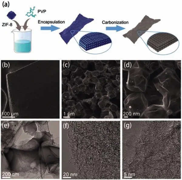
Fig.1.(a) Schematic illustration of the synthesis of ZPDC.(b–d) SEM images of ZPDC.(e–g) TEM images of ZPDC.
Herein,we report a facile and scalable method to synthesize the porous carbon anode by directly carbonization of the mixture of ZIF-8 and PVP made by solution process.The as-prepared porous carbon shows the macroscopic sheet-like morphology,which has the expanded interlayer spacing,highly disordered structure,abundant pore structure,and nitrogen doped properties.Electrochemical results demonstrate that ZIF-8 and PVP derived porous carbon(ZPDC) exhibits the enhanced K+charge storage properties in specific capacity,rate capability,and cycling stability.Moreover,full cell PICs are assembled by using ZPDC as the anode and homemade porous carbon as the cathode,which can operate at a high working voltage up to 4.2 V and deliver a maximum energy density of 85.12 Wh/kg and power density of 11.86 kW/kg as well as long cycle lifespan over 3000 cycles.
Fig.1a shows the typical synthesized procedure of ZPDC.In this procedure,a certain amount of zinc zeolitic imidazolate framework(ZIF-8) with an average diameter of 1.8 μm and PVP was homogeneously mixed in water,and then dried to form a white sheet with a thickness of ∼0.4 mm (Figs.S1 and S2 in Supporting information).SEM images in Fig.S1 show that ZIF-8 particles are homogeneously embedded into PVP matrix.In addition,the pristine polyhedral morphology of ZIF-8 is slightly changed,which may be related to the PVP coated on the surface of ZIF-8 particles.The white sheet was further pyrolyzed at 1000 °C in an Ar atmosphere,resulting in a porous ZPDC sheet with a thickness of ∼0.22 mm.The morphology and structure of as-prepared ZPDC sheet were studiedviascanning electron microscopy (SEM) and transmission electron microscopy (TEM).As shown in Figs.1b and c,as-prepared ZPDC sheet is composed by the well-connected micro-boxes with an average diameter of 1.1 μm.High-resolution SEM image (Fig.1d)and TEM image (Fig.1e) show that micro-boxes inherit the polyhedral shape of ZIF-8 particles,but with slight deformation.The slight deformation of micro-boxes may be related to PVP addition.During the pyrolysis,the PVP gel was transformed into a stiff carbon shell coated on ZIF-8 particles at a low pyrolyzed temperature [20].Further elevated the pyrolyzed temperature,ZIF-8 particles enclosed in PVP derived carbon shell start to decompose,release the decomposed gas,and then shrink,finally resulting in a porous carbon,while the PVP derived carbon shell deforms slightly due to the shrinkage of ZIF-8 template.Therefore,PVP was used here as an adhesion agent to bind the ZIF-8 particles to form the ZIF-8/PVP composite sheet and as the additional carbon source to form the carbon shell,thus connecting the ZIF-8 derived carbon together for generating macroscopic porous carbon framework.Similar shell-core structure also observed in other works on ZIF-8/PVP and ZIF-8/agarose derived porous carbon [20,21].For comparison,ZIF-8 particles without PVP addition were transformed into regularly polyhedral carbon with an average particle size of 0.66 μm under the same condition (Fig.S2).High-resolution TEM images(Figs.1f and g) show that the carbon framework of ZPDC is composed by a three-dimensional (3D) distribution of nanopores with highly curved atom-thick walls.Energy dispersive X-ray spectrometry (EDS) mapping (Fig.S3 in Supporting information) demonstrates the uniform distribution of N and O heteroatoms over the carbon matrix of ZPDC.
Fig.2a shows the XRD patterns of ZPDC and ZDC samples.The XRD patterns of ZDC shows the two broaden peaks located around 25.18oand 43.29o,corresponding to the (002) and (100)plane of graphite,respectively.The calculated interlayer distance of ZDC is approximate 3.53 ˚A.No diffraction peaks related to metal Zn are observed,indicating the metal Zn is mainly evaporated at 1000 °C.After the PVP addition,the as-prepared ZPDC sample shows the similar profile of XRD pattern with ZDC except for a slight down-shift of (002) peak with a shift value of 0.7o,indicating the expanded interlayer structure of ZPDC.The interlayer distance of ZPDC is calculated to be 3.63 ˚A,which is consistent with TEM observation.This expanded inter-graphene spacing may facilitate the fast K+intercalation into the bulk of the ZPDC anode.The broaden XRD peaks also imply the poor crystallinity and low degree of graphitization of ZPDC and ZDC samples.Meanwhile,Scherr’s equation was used to determine the average graphene domain height (Lc)viausing the full width at half maximum values of (002) peaks [22,23].The Lc values for ZDC and ZPDC can be approximately determined to be 0.86 and 0.82 nm,respectively.Therefore,the graphene domains for ZPDC and ZDC samples are mainly composed by about two or three layer-stacked curved graphene sheets (e.g.,0.82/0.34=2.4).The carbon structure of as-prepared samples is further studied by Raman spectroscopy(Fig.2b).Two broad peaks are found in these two samples,which can be assigned to broad disorder-induced D-bands and in-plane vibration G-bands at around 1346 cm−1and 1585 cm−1,respectively.The degree of graphitic ordering can be evaluated from the integral intensity value ratio between D- and G-band (ID/IG).ID/IGvalues for ZDC and ZPDC are calculated to be 2.27 and 2.31,respectively.According to the reported equation [24,25],the average domain size (La) of ZDC and ZPDC are 8.63 and 8.48 nm,which are close to other reports on MOFs derived porous carbons with the disordered structure and large defects [14,23,26–28].
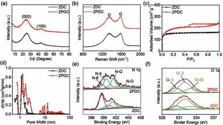
Fig.2.Structural Characterization of ZDC and ZPDC: (a) XRD patterns.(b) Raman spectra.(c) Nitrogen adsorption-desorption isotherm curves.(d) Pore-size distribution curves.(e) N 1s XPS spectra.(f) O 1s XPS spectra.
The pore structure of as-prepared samples was studied by N2adsorption/desorption isotherms.As shown in Fig.2c,the isotherm for ZPDC samples shows a type H4loops and does not exhibit any limiting adsorption at highP/P0,which is associated with micropores and narrow slit pores.The pore-size distribution curve of ZPDC further shows the presence of micro-/meso-pores in 1–3 nm size range as well as a handful of mesopores ranging from 6 nm to 50 nm (Fig.2d),suggesting the hierarchical porous architecture of MDPC.For comparison,ZDC exhibits the typical Ⅰsorption isotherms (Fig.2c).The pore-size distribution of ZDC shows that the pores size mainly centers around 1–2 nm,suggesting the microporous structure (Fig.2d).ZPDC has a high Brunauer-Emmett-Teller (BET) surface area of 705.52 m2/g and a high pore volume and 0.38 cm3/g,which are higher than that of ZDC (591.30 m2/g and 0.26 cm3/g).The X-ray photoelectron spectroscopy (XPS) was further employed to disclose the surface characterization of asprepared porous carbon.From Fig.S4a (Supporting information),both ZDC and ZPDC samples are mainly composed by C,O,and N elements.The N and O contents in ZDC sample are about 7.62%and 6.23%,respectively.For ZPDC samples,the N content decreases to 4.16%,while the O contents increases to 9.42%.The high- resolution C 1s spectrum (Fig.S4b in Supporting information) of ZPDC and ZDC can be fitted into C–C (284.70 eV),C–O/C–N (285.85 eV)and C=O (288.6 eV) bands [29].The N 1s spectrum of ZPDC can be deconvoluted into four peaks centered at 398.6 eV,400 eV,401.1 eV,and 403.1 eV,which can be assigned to pyridinic N (N-6),pyrrolic N (N-5),quaternary N (N-Q) groups,and oxidized-N groups (Fig.2e),respectively [30,31].The proportional differences of these three N-related groups between ZPDC and ZDC can be associated to PVP addition.The O 1s spectrum (Fig.2f) of ZPDC and ZDC can be fitted into three peaks around 530.40,531.98 and 533.10 eV,corresponding to C=O quinone groups (O–Ⅰ),C–OH hydroxylic groups or C–O–C either groups (O–Ⅱ) and–O–C=O carboxyl groups (O–Ⅲ),respectively [27,32].The above XPS spectra demonstrates that as-synthesized carbon anode is a nitrogen and oxygen heteroatoms co-doped carbon,which may increase the active sites for potassiation and improve the wettability to increase the active surface area.
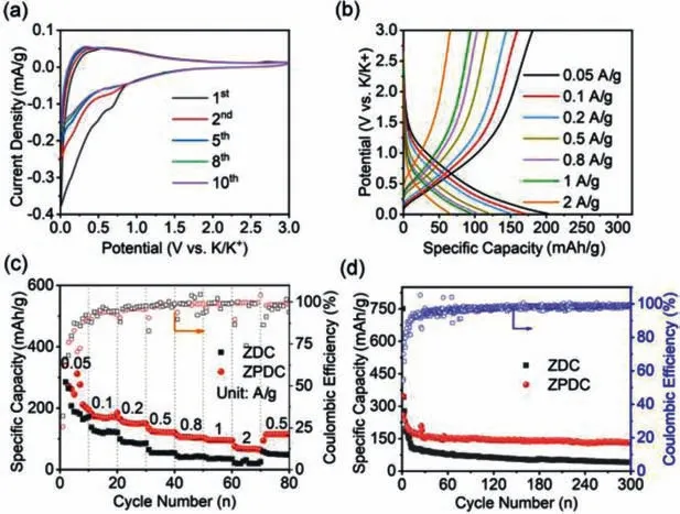
Fig.3.Electrochemical characterization of ZPDC electrode: (a) CV curves.(b) Charging/discharging curves.(c) Rate capability at various current densities ranging from 0.05 A/g to 2 A/g.(d) Cycling stability at 0.1 A/g (initial 10 cycles at 0.05 A/g).
Half-cell configurationversusK metal was employed to study the electrochemical performance of as-prepared porous carbons anode.Fig.3a shows the CV curves of ZPDC at a sweep rate of 0.2 mV/s within a potential range of 0.01–3.00 V (vs.K+/K).In the initial cathodic process,the cathodic current increases rapidly after the potential less than 0.7 V (vs.K+/K),which is related to the irreversible reactions and the simultaneous formation of solid electrolyte interface (SEI) [29].During the following anodic scan,only one hump is observed around 0.5 V (vs.K+/K),indicates the stepwise extraction of K+from K-intercalated carbon and followed continuous reversible reactions between the K+and surface functional groups [27–32].After the several cycles,the CV curves tend to overlap,indicating the good reversibility of K+inter/detercalated process.Fig.3b shows the typical charge/discharge curves under the different current densities ranging from 0.05 A/g to 2 A/g.These charge/discharge curves exhibit a slope profile without the voltage plateau,which is similar with other reported porous carbon or heteroatom doped carbon anodes [17,29–33].The rate capability of ZPDC was evaluated and plotted in Fig.3c.The specific capacities of ZPDC are calculated to be 202.9,170.6,149.8,120.5,104.2,95.2 and 63.8 mAh/g,corresponding to the charge/discharge current density of 0.05,0.1,0.2,0.5,0.8,1.0 and 2.0 A/g,respectively.When the current density resets to 0.5 A/g,ZPDC still delivers a high specific capacity of 116.2 mAh/g.ZPDC electrode shows the relatively low columbic efficiency at the initial cycles (25.6% for first cycle),which is mainly associated to the formation of SEI layer and irreversible side reactions on the surface of ZPDC electrode [29–32].The low columbic efficiency could be alleviated by pre-potassiation process and electrolyte additives.As the current density exceeding 0.2 A/g,the columbic efficiency values are close to 100% in the followed rate-test process.We also noted that the specific capacity values of ZPDC are higher than ZDC,which may be associated to hierarchical pore structure and interconnected features of ZPDC,thus facilitating the electron and ions transfer.ZPDC anode also exhibits the good cycling stability.As shown in Fig.3d,ZPDC anode exhibits a high reversible capacity of 132.8 mAh/g after 300 cycles at 0.1 A/g,corresponding to a capacity retention ratio of 76.3%.As the cycling current density increases to 1.0 A/g,ZPDC still preserves 77.2% of initial specific capacity after 300 cycles (Fig.S5 in Supporting information).
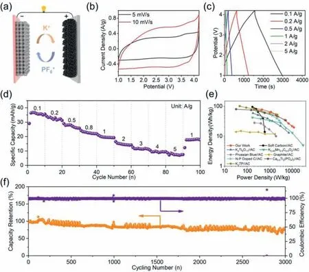
Fig.4.Electrochemical performance of ZPDC//PDPC PICs: (a) Schematic illustration of this KIC.(b) CV curves.(c) Galvanostatic charge/discharge curves.(d) Specific capacities under the different discharging current densities.(e) Ragone plots showing energy and power densities vs.other reports.(f) Long-term cycling performance at 1 A/g.
The kinetics of potassiation and depotassiation for ZPDC was evaluatedviagalvanostatic intermittent titration technique (GITT).Fig.S6a (Supporting information) shows the potential response of ZPDC electrode during the GITT test under a current density of 0.1 A/g.The diffusion coefficient K+(Dk) values calculated by solving Fick’second law based on the GITT potential curves were plotted in Fig.S6b (Supporting information).During the cathodic process,the Dkvalue for ZPDC slightly increase initially,and then decrease rapidly below 0.5 V.Therefore,the diffusion kinetics of K+with heteroatoms or defects occurred at high voltage range is higher than that of K+inserted into carbon layer occurred at low voltage range.While a reverse trend was observed in the anodic process.The Dkvalue for ZPDC decreases continuously first before reaching at 0.7 V,raises slightly between 0.7–1.2 V,and then decreases gradually before reaching the upper cutoff voltage.The Dkvalues for ZPDC during the potassiated and depotassiated process are higher than that of ZDC,which indicates that the unique wellconnected micro-box structure is conducive to K+diffusion in the carbon matrix.EIS measurements on ZPDC electrode in half cell were also carried out at the working potential range from 0.01–3 Vvs.K/K+with an elevated potential of 0.5 V,the corresponding results were plotted in Fig.S7 (Supporting information).All of the EIS plots feature the semi-circle in the high-frequency region and oblique line in the low-frequency region,corresponding to electron/charge transfer resistance at the electrolyte-electrode surface and the Warburg impedance of K+diffusion in ZPDC electrode,respectively [15,24].The electron/charge transfer resistance shows little change at the high potassiated voltage and largely increases as the potassiated potential less than 1 Vvs.K/K+.This may be associated to that the reduced charge transfer kinetics and the variation of SEI at the low potential range.The slope of oblique line at low-frequency decreases gradually with the increase of discharge depth,indicating the decreased K+diffusion kinetics in ZPDC matrix [15].The above EIS results are consistent with the observation of CVs and GITT characterizations.
To further demonstrate the potential of ZPDC in KICs,a prototype full cell was fabricated by using ZPDC as anode and homemade polyaniline derived porous carbon (PDPC) as capacitive-type cathode in KPF6based organic electrolyte,as schematically illustrated in Fig.4a.More details about PDPC can be seen in our previous report [7].In view of the electrochemical performance of asfabricated KICs with the different anode/cathode mass ratio,the optimal ratio is 1:1 (Fig.S8 in Supporting information).Figs.4b and c show thequasi-rectangular CVs and the symmetric linear charge/discharge curves within a potential range of 1–4.2 V,respectively,indicating a typical capacitive behavior for as assembled ZPDC//PDPC KICs.The specific capacities of ZPDC//PDPC KIC were calculated to 35.6,31.2,25.8,21.9,19.2,14.2,11.2,9.5 and 7.5 mAh/g at the charge/discharge densities of 0.1,0.2,0.5,0.8,1,2,3,4 and 5 A/g,respectively,as shown in Fig.4d.The energy and power densities of the ZPDC//PDPC KIC are further evaluated and are plotted in Fig.4e.The ZPDC//PDPC KIC delivers a high energy density of 85.12 Wh/kg at a power density of 207.89 W/kg.Even at a high-power density of 11.86 kW/kg,this KIC can still provide an energy density of 19.76 Wh/kg.The energy and power performance of this KIC is compared favorably with state-of-the-art KICs in the literature [10,11,33–40].Furthermore,ZPDC//PDPC KIC also exhibits an acceptable cycle stability with a capacity retention of 76% after 3000 cycles at a constant charge/discharge current density of 1 A/g with a high coulombic efficiency of ∼100% during whole cycling(Fig.4f).
In summary,we synthesized porous carbon sheets with several centimeters by directly carbonization of the mixture of ZIF-8 and PVP made by solution process.The porous carbon sheet is composed by the well-connected micro-boxes in which ZIF-8 was used as template to form inner porous matrix and PVP as the binder to form the carbon shell during the carbonization.The as-prepared porous carbon sheets had the abundant micro/mesopores,large interlayer spacing and nitrogen doping property.Such favorable structure enables this porous carbon to provide large active sites and shorten diffusion path for K+storage.Electrochemical results demonstrate the high and stable K+charge storage properties.An assembled PIC was assembled by employing this ZPDC electrode as an anode combined with a home-made porous carbon as the cathode,which delivers a high operation working voltage up to 4.2 V,a high energy density of 85.12 Wh/kg and a high-power density of 11.8 kW/kg.The present work provides a new insight on the fabrication of MOFs derived composites towards to the low-cost carbon anodes for energy storage devices.
Declaration of competing interest
The authors declare that they have no known competing financial interests or personal relationships that could have appeared to influence the work reported in this paper.
Acknowledgments
This work was supported by National Natural Science Foundation of China (No.51902188),Key Research &Development Program of Shandong Province (No.2019JZZY010355),Natural Science Foundation of Jiangsu Province (No.BK20190207),and the CAS Key Laboratory of Carbon Materials (No.KLCMKFJJ2006).
Supplementary materials
Supplementary material associated with this article can be found,in the online version,at doi:10.1016/j.cclet.2021.08.101.
 Chinese Chemical Letters2022年3期
- Chinese Chemical Letters的其它文章
- Direct catalytic nitrogen oxide removal using thermal,electrical or solar energy
- Construction and applications of DNA-based nanomaterials in cancer therapy
- Recent research progress of bimetallic phosphides-based nanomaterials as cocatalyst for photocatalytic hydrogen evolution
- Nanostructured materials with localized surface plasmon resonance for photocatalysis
- Recent progress of Pd/zeolite as passive NOx adsorber: Adsorption chemistry,structure-performance relationships,challenges and prospects
- Microfluidic methods for cell separation and subsequent analysis