
Self-assembly of single metal sites embedded covalent organic frameworks into multi-dimensional nanostructures for efficient CO2 electroreduction
2022-06-18 10:53YiLuYngYiRongWngGungKuoGoMingLiuChngMioLeYnLiWeiChengZiYueZhoYifChenZhifengXinShunLiLiDongShengLiQinLn
Chinese Chemical Letters 2022年3期
Yi-Lu Yng,Yi-Rong Wng,Gung-Kuo Go,Ming Liu,Chng Mio,Le-Yn Li,Wei Cheng,Zi-Yue Zho,Yif Chen,b,∗,Zhifeng Xin,Shun-Li Li,Dong-Sheng Li,Y-Qin Ln,b,∗
a Jiangsu Collaborative Innovation Centre of Biomedical Functional Materials,Jiangsu Key Laboratory of New Power Batteries,School of Chemistry and Materials Science,Nanjing Normal University,Nanjing 210023,China
b School of Chemistry,South China Normal University,Guangzhou 510006,China
c Institute of Molecular Engineering and Applied Chemistry,Anhui University of Technology,Ma’anshan 243002,China
d College of Materials and Chemical Engineering,Hubei Provincial Collaborative Innovation Center for New Energy Microgrid,Key Laboratory of Inorganic Nonmetallic Crystalline and Energy Conversion Materials,China Three Gorges University,Yichang 443002,China
Keywords:CO2 electroreduction Covalent organic frameworks Hollow sphere Nanofiber Nanosheet
ABSTRACT Morphology-controlled electrocatalysts with the ability of CO2 adsorption/activation,mass transfer,high stability and porosity are much desired in electrochemical CO2 reduction reaction (CO2RR).Here,three kinds of multi-dimensional nanostructures (i.e.,hollow sphere,nanosheets and nanofibers) have been successfully produced through the modulation of porphyrin-based covalent organic frameworks (COFs)with various modulators.The obtained nanostructures with high-stability,large surface-area,and single metal sites enable efficient CO2RR into CH4.Notably,they all exhibit higher FECH4 (hollow sphere,68.2%;nanosheet,64.2% and nanofiber,71.0%,−0.9 V) than COF-366-Cu (43.0%,−0.9 V) after morphology control.Noteworthy,the FECH4 of COF-366-Cu (HS) keeps higher than 52.4% over a wide potential range from −0.9 V to −1.1 V and the achieved FECH4+C2H4 (82.8%,−0.9 V) is superior to most of reported COFs and copper-based electrocatalysts.This work paves a new way in the exploration of COF-based multidimensional nanostructures applicable in efficient CO2RR to CH4.
Electrochemical CO2reduction reaction (CO2RR) holds high promise in the conversion of thermodynamically stable and chemically inert CO2into valuable products (e.g.,CO,formic acid,CH4,C2H4and ethanol),which might be an alternative way to deal with the intermittent nature of renewable energy sources [1-3].However,the competitive process of hydrogen evolution reaction (HER)in water and the similar redox potentials of various CO2reduction reactions usually disqualify the catalysts that would result in poor selectivity,high overpotential,low conversion efficiency,etc.[4].Since the performances of various electrochemical energy conversion technologies are dominated by the electrocatalysts,it is critical to construct electrocatalysts with advantages like favorable catalytic activity,desired selectivity and superior durability to solve these problems [5].
Covalent organic frameworks (COFs),an attractive family of crystalline porous polymeric networks featured with predesigned geometries and well-defined pore structures,have evoked an immense level of recent interest around the world [6-8].Because of their advantages like excellent crystallinity,tunable structures or porosity,high stability and low densities,they have attracted extensive attention in various fields,such as energy storage [9],gas separation [10],sensing [11],photoluminescence [12],proton conduction [13],drug delivery [14]and heterogeneous catalysis [15].COFs are desired electrocatalsyts in CO2RR owing to the following reasons [16,17]: (1) the well-defined structures enable the exact location control of active sites [18];(2) the abundant channels and large surface area can facilitate the mass transfer and CO2adsorption/enrichment [19];(3) the porous structures of COFs may be beneficial for the confinement of functional moieties such as single atoms or small nanoparticles [20]and (4) the high stability of COFs set basis for the durability in long-term tests even under harsh experimental conditions [21].Besides,COFs as crystalline platforms could provide insightful understanding of structure-activity correlations in electrocatalysis,resulting in new guiding knowledge for rational design and exploitation of novel electrocatalysts[21].Up to date,some pioneering COF-based materials including porphyrin-based COFs like COF-366-Co and COF-367-Co [22],or phthalocyanine-based COFs like CoPc-PDQ-COF [23]and NiPc-COF[24]have been applied in electrocatalytic CO2RR.However,most of the reduced products when applying COFs as the electrocatalysts are two-electron transferred products like CO and the effi-cient generation of higher-value products (e.g.,CH4and C2H4) involving multiple proton-coupled electron transfer (PCET) remains as a scientific challenge.Besides,there are still some remaining problems that have restricted the development of COFs in broader range of applications,for example,the relatively complicated or stricted synthesis process,lacking in morphology controlled strategies or large scale production [25].Among them,the morphology tuning of COFs that can shape COFs into regular nanostructures and control the exposed defects or sites are essential to make better use of COFs before they can be widely adopted in practical applications.Therefore,strategies that enable processing COFs into desired and well-tuned morphology that possess positive effect on applications like electrocatalytic CO2RR are highly demanded.
During past decades,various morphology-controlled strategies have been reported for COFs and can be mainly classified as“top-down” and “bottom-up” strategies [25,26].The “top-down”strategies like liquid phase exfoliation have been reported to transform bulk phases of COFs into lower-dimension forms like nanosheets through methods like self-exfoliation [27,28],chemical exfoliation [29,30]or mechanical exfoliation [31,32].However,they are still limited by the entangled drawbacks of presynthesized COFs,low yields,in-homogeneity in the size or thickness,etc.[33].Besides,the generated forms are relatively simple and most of them are nanopellets or nanosheets [34,35].In contrast,“bottom-up” strategies that enable simultaneousin-situsynthesis and morphology-control of COFs have been further explored.In “bottom-up” strategies,template and template-free methods have been investigated [36,37].In the reported template methods,COFs are firstly grown on the surface of templates (e.g.,ZnO and Fe3O4) with pre-designed morphologies (e.g.,spherical or tubular shapes) followed with the removal of templates to produce shaped morphology [38,39].However,they still have drawbacks like sophisticated template-removal processes,residues problems and relatively complicated processes.In contrast,template-free “bottomup” approaches are much more desired in both synthesis and morphology-control processes,in which COFs are firstly formed as small crystallites and then self-assembled into target morphology in the absence of template [40].During these processes,diverse conditions like additives [41,42],solvent compositions [43]or polarity [44],substrate species [43],reactant concentrations [45]and the monomer’s planarity [46]can induce the crystal growth process of COFs to obtain different morphologies.
Some pioneering works have been reported to tune COFs into various nanostructures like nanosheets,nanospheres or nanofibers and investigate their potential applications in trypsin immobilization [47],energy storage [48]or guest molecule capture [49],etc.Nonetheless,the investigation of COFs in this field is still at the early stage and the exploration of new methods that enable processing of COFs into valuable nanostructures are much desired for a broader range of applications.It would be highly important to study the effects of various morphologies on the CO2RR properties and particularly attractive to explore the possibility of COF-based nanostructures in selective production of multi-electron transferred products (e.g.,CH4or C2H4).

Fig.1.The schematic representation of porphyrin COF-based nanostructures in electrocatalytic CO2RR (Ani stands for aniline and TEPA is tetraethylenepentamine).
Herein,three kinds of nanostructures (i.e.,hollow spheres,nanofibers and nanosheets) have been synthesized on the basis of COF-366-Cu to explore their CO2RR performance (Fig.1).The formation process has been revealed as supported by time-interval experiments.Thus-obtained COF-366-Cu with various nanostructures can serve as powerful electrocatalysts in CO2RR,in which the porous nanostructures possess excellent chemical stability,large surface area,CO2adsorption/activation properties and tremendous Cu-N4sites,etc.Specifically,COF-366-Cu (HS),COF-366-Cu (NF)and COF-366-Cu (NS) exhibit superior FECH4of 68.2% (−285.4 mA/cm2,−0.9 V),71.0 % (−350.8 mA/cm2,−0.9 V) and 64.2%(−276.0 mA/cm2,−0.9 V) in flow-cell,respectively.Besides,the achieved FECH4+C2H4(82.8%,−0.9 V) of COF-366-Cu (HS) is superior to most of reported COFs and copper-based electrocatalysts.This is a rarely reported example of porphyrin-based COFs with unique and tunable mult-dimensional nanostructures applied in efficient CO2RR to CH4as far as we know,which would expand the applications of COFs in CO2RR.
For the syntheses of various COF-366-Cu based nanostructures,different additives including aniline (Ani),hydrazine hydrate(N2H4•H2O),tetraethylenepentamine (TEPA),triethylenetetramine(TETA),ammonium fluoride (NH4F),ammonium bromide (NH4Br),ammonium chloride (NH4Cl),etc.,have been applied in the synthesis procedures.In detail,these additives are added into the precursors of COF-366-Cu and reacted under similar conditions as that of COF-366-Cu [22].During the synthesis process of COF-366-Cu,the addition of various modulators can shape the COF morphology and result in multi-dimensional nanostructures including hollow spheres (sample with the addition of 5 μL Ani,denoted as COF-366-Cu (HS)),nanofibers (addition of 5 μL TEPA,COF-366-Cu (NF))and nanosheets (addition of 5 mg NH4F,COF-366-Cu (NS)).
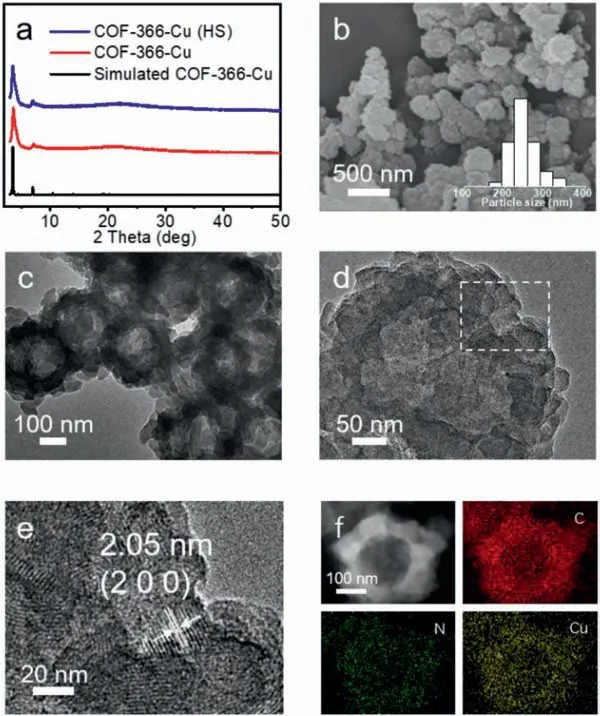
Fig.2.The structure and characterization of COF-366-Cu (HS).(a) The PXRD of COF-366-Cu (HS).(b) SEM image of COF-366-Cu (HS).(c) TEM image of COF-366-Cu(HS).(d) HRTEM image of COF-366-Cu (HS).(e) Part of the amplification of HRTEM image of COF-366-Cu (HS).(f) STEM and mapping images of COF-366-Cu (HS).
To study the components and crystallinity,powder X-ray diffraction (PXRD) and Fourier-transform infrared spectroscopy (FTIR) tests have been conducted.Taking COF-366-Cu (HS) as an example,it exhibits high crystallinity with a series of strong PXRD peaks at 3.5°,4.2° and 6.9°,which are assigned to (1 1 0),(2 0 0) and (2 2 0) crystal facets,respectively (Fig.2a) [22].In the case of COF-366-Cu (NF) and COF-366-Cu (NS),the PXRD patterns are also similar to that of COF-366-Cu (Fig.S1 in Supporting information).In the FT-IR spectra,similar peaks at 1622 cm−1in COF-366 and COF-366-Cu confirm the successful formation of C=N bond in the structures,accompanied by the diminish of C=O (1697 cm−1)stretching band of terephthalaldehyde (BDA) and N-H (3324 cm−1)stretching band of Cu-TAPP (Fig.S2 in Supporting information)[50].COF-366-Cu (HS),COF-366-Cu (NF) and COF-366-Cu (NS) display similar peaks as that of COF-366-Cu (Fig.S3 in Supporting information).Furthermore,X-ray photoelectron spectroscopy (XPS)measurements have been conducted to determine the surface electronic state and elemental composition of COF-366-Cu (Fig.S4 in Supporting information).The observed binding energy of 934.86 eV and 954.69 eV are ascribed to Cu 2p3/2and Cu 2p1/2in COF-366-Cu,respectively (Fig.S5a in Supporting information) [51,52].Besides,the XPS results of COF-366-Cu (HS),COF-366-Cu (NF) and COF-366-Cu (NS) display similar results when compared with that of COF-366-Cu,revealing the remained bivalent state of Cu(II) in these materials (Figs.S5b-d in Supporting information).
To evaluate the morphology of these samples,scanning electron microscopy (SEM) and transmission electron microscopy (TEM)tests have been performed.Taking the additive of 5 μL Ani as an example,the obtained sample displays sphere morphology with a diameter of ∼248 ± 71 nm as proved by the SEM image (Fig.2b).Interestingly,it shows hollow sphere morphology (COF-366-Cu (HS)) with a wall thickness of ∼86 ± 33 nm in the TEM image (Fig.2c).In contrast,COF-366-Cu synthesized from normal condition displays irregular particle morphology as proved by the SEM and TEM images (Fig.S6 in Supporting information).Furthermore,clear lattice fringes on the hollow spherical walls are visible in high-resolution TEM (HRTEM) images and the lattice spacing of 2.05 nm is assigned to the (2 0 0) planes,confirming the high crystallinity of obtained COF-366-Cu (HS) (Figs.2d and e) [22].Moreover,the corresponding energy dispersive X-ray (EDS) element mapping of COF-366-Cu (HS) shows that C,N,O and Cu elements are uniformly distributed in the hollow sphere (Fig.2f).Besides,the hollow sphere morphology is further certified by the EDS linear scanning test,in which a volcano-type of distribution curve can be detected for Cu element (Fig.S7 in Supporting information).The Cu content in COF-366-Cu (HS) is determined to be 5.30 wt% by inductively coupled plasma (ICP) optical emission spectrometry test,matches well with the result in EDS test (Fig.S8 and Table S1 in Supporting information).
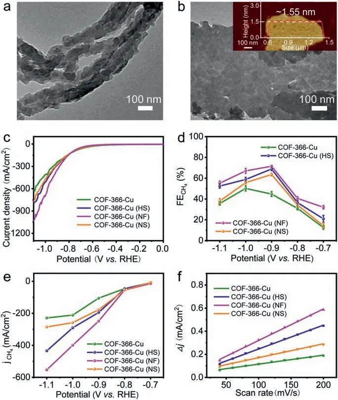
Fig.3.Electrocatalytic performances.(a) TEM image of COF-366-Cu (NF).(b) TEM image of COF-366-Cu (NS).(c) LSV curves of COF-366-Cu,COF-366-Cu (HS),COF-366-Cu (NF) and COF-366-Cu (NS).(d) FECH4 calculated over potential range from−0.7 V to −1.1 V.(e) Partial CH4 current density.(f) Capacitive current at −0.03 V as a function of scan rate for COF-366-Cu,COF-366-Cu (HS),COF-366-Cu (NF) and COF-366-Cu (NS).
Furthermore,the morphology of COF-366-Cu with various addition amounts of Ani (3-50 μL) have been investigated.The PXRD patterns of them exhibit high and remained crystallinity when compared with that of COF-366-Cu (Fig.S9 in Supporting information).With the addition of 3 μL Ani,the sample with the hollow sphere morphology is obtained (diameter,371 nm,wall thickness,∼107 ± 95 nm) and transformed into COF-366-Cu (HS) with the addition of 5 μL Ani as presented above (Figs.2b and c,Fig.S10 in Supporting information).When the amount is increased to 10 μL(diameter,350 nm,wall thickness,∼84 ± 81 nm) (Fig.S11 in Supporting information) or 30 μL (diameter,560 nm,wall thickness,∼160 ± 150 nm),the sizes of hollow spheres gradually become larger (Fig.S12 in Supporting information).When it increases to 50 μL,the hollow sphere morphology disappears,and it changes into aggregated and irregular pellets (∼5 μm) (Fig.S13 in Supporting information).Besides,the morphology tuning with other additives have also been investigated.The addition of N2H4•H2O (5 μL)in the synthesis of COF-366-Cu can also result in the morphology of hollow spheres (diameter,∼350 nm and wall thickness,∼140 ±97 nm) as proved by the PXRD,SEM and TEM images (Figs.S14 and S15 in Supporting information).Interestingly,when TEPA (5 μL) and TETA (5 μL) are applied as the modulators,they can both result in nanofiber morphology (Fig.3a and Fig.S17 in Supporting information).Taking the addition of 5 μL TEPA as an example,the obtained nanofibers (COF-366-Cu (NF)) display remained crystallinity with a length of ∼1 μm and a diameter of ∼100 nm as proved by the PXRD and TEM tests (Fig.3a and Fig.S16 in Supporting information).Besides,when the additive is NH4F (length,∼994± 62 nm and width,∼752 ± 376 nm),NH4Cl (length,994 nm and width,752 nm) and NH4Br (length,1372 nm and width,1181 nm) (Fig.S18 in Supporting information),they are all nanosheets(Fig.3b,Figs.S19 and S20 in Supporting information).Taking the addition of 5 mg NH4F as an example,atomic force microscope(AFM) tests have been conducted to evaluate the thickness of the obtained COF-366-Cu (NS).The results show that the thickness of COF-366-Cu (NS) is ∼1.55 nm over a large scale (∼1 μm) (Fig.3b).Therefore,some of the obtained sample with representative morphology like COF-366-Cu (HS) (addition of 5 μL Ani),COF-366-Cu(NF) (addition of 5 μL TEPA) and COF-366-Cu (NF) (addition of 5 mg NH4F) will be selected as the desired platforms to further investigate other properties.
The morphology tuning is based on the self-assembly of COF-366-Cu with porous structure,which might be beneficial for the mass transfer of substrates and enrichment of CO2.To further evaluate the porosity of these samples,N2and CO2sorption tests have been carried out.The Brunner-Emmet-Teller surface area (SBET) of COF-366-Cu (HS),COF-366-Cu (NF) and COF-366-Cu (NS) are calculated to be 566,356 and 413 cm2/g,respectively (Figs.S21–S24 in Supporting information).Besides,the pore volume values for COF-366-Cu (HS),COF-366-Cu (NF) and COF-366-Cu (NS) are detected to be 0.53 cm3/g,0.50 cm3/g and 0.48 cm3/g,respectively.The difference in the SBETand pore volume might be attributed to the varied exposed defects in these nanostructures.Moreover,CO2sorption tests conducted at 298 K reveal that COF-366-Cu (HS),COF-366-Cu (NF) and COF-366-Cu (NS) display similar CO2adsorption capacity of ∼20 cm3/g when compared with that of COF-366-Cu,implying the remained CO2adsorption ability after morphology tuning (Fig.S25 in Supporting information).Besides,the catalysis stability,as a vital factor to determine the durability of samples,has also been evaluated.To investigate the chemical stability,the samples are soaked in 1 mol/L KOH for more than 24 h and characterized.PXRD patterns reveal that COF-366-Cu (HS),COF-366-Cu (NF),COF-366-Cu (NS) and COF-366-Cu all present remained crystallinity when compared with samples before tests,indicating the high chemical stability (Fig.S26 in Supporting information).Besides,thermogravimetric analysis (TGA) tests have been performed under oxygen atmosphere to evaluate the thermal stability.COF-366-Cu (HS),COF-366-Cu (NF) and COF-366-Cu (NS) all exhibit high thermal stability with slight weight loss up to ∼300°C,complying with the result of COF-366-Cu (Figs.S27 and S28 in Supporting information).The high porosity and stability combined with well-tuned morphology as mentioned above would set fundamental basis for further applications in electrocatalytic CO2RR.
In addition,we further study the formation process of COF-366-Cu (HS),COF-366-Cu (NF) and COF-366-Cu (NS) at different reaction time.Taking COF-366-Cu (HS) as an example,PXRD tests show that the peaks of COF-366-Cu (HS) start to appear at 1 h and the peak intensity increases from 1 h to 72 h,implying COF-366-Cu(HS) is gradually transformed into higher crystalline states along the time (Fig.S29 in Supporting information).Furthermore,the SEM image shows that COF-366-Cu (HS) displays small nanoparticle (∼50 nm) morphology at 0.5 h (Fig.S30a in Supporting information).Then,these small nanosheets grow up and self-assembled into hollow spheres (diameter,∼200 nm) (Fig.S30b in Supporting information).After that,the hollow sphere gradually becomes larger in size and the final size is ∼250 nm at 72 h (Figs.S30c and d in Supporting information).For COF-366-Cu (NF),it grows from short nanofibers (length ∼370 nm) at 3 h (Fig.S31b in Supporting information),and then it gradually becomes longer with length of∼750 nm at 6 h (Fig.S31c in Supporting information).Finally,the obtained nanofibers display a length of ∼1 μm and a diameter of∼100 nm as proved by the TEM image (Fig.3a and Fig.S31d in Supporting information).Based on the above results,the possible reason proposed for the formation of nanofibers might be the vital role of diamine-appended analogs like TEPA and TETA,in which the amino groups at both ends of the molecule might participate in the condensation of aldehydes and amines,thus connecting the generated small nano-precursors during the formation process and result in long nanofibers.For COF-366-Cu (NS),firstly,they formed small nanoparticles (thickness,∼150 nm;diameter,∼350 nm) at 3 h (Fig.S32b in Supporting information).With the increase of time,they gradually become larger along the time and the produced nanosheets at 72 h possess a thickness of ∼1.55 nm over a large scale (∼1 μm) as proved by the AFM and TEM tests (Fig.3b,Figs.S32c and d in Supporting information).
The specially designed COF-366-Cu (HS),COF-366-Cu (NF) and COF-366-Cu (NS) with well-tuned morphology,high porosity and excellent stability might serve as the desired platforms in electrochemical CO2RR.To test their performances,the catalysts are packaged in flow cells and tested in three-electrode electrochemical system at selected potentials.The working electrode is a catalyst spray-coated gas diffusion layer (GDL).An anion exchange membrane is inserted between the cathode and Pt foil.In this work,all the potentials are measured using a Ag/AgCl electrode and the results are reported relative to reversible hydrogen electrode (RHE).
Linear sweep voltammetry (LSV) curves show that COF-366-Cu (HS),COF-366-Cu (NF) and COF-366-Cu (NS) have total current density of −285.4 mA/cm2,−350.8 mA/cm2and −276.0 mA/cm2at−0.9 V,respectively,which are all superior to COF-366-Cu (−244.4 mA/cm2) at −0.9 V (Fig.3c).Besides,COF-366-Cu,COF-366-Cu(HS),COF-366-Cu (NF) and COF-366-Cu (NS) all have much smaller current density in HER than that in CO2RR,indicating they strongly favor CO2RR than HER (Figs.S33–S36 in Supporting information).In order to evaluate the reduction product of CO2RR,electrocatalysis reactions are carried out at different potentials and the reduction products are detected by gas chromatography (GC) and1H nuclear magnetic resonance spectroscopy (1H NMR),respectively.As a result,there are no liquid products detected (Fig.S37a in Supporting information).For COF-366-Cu (HS),it gives a FECH4of 68.2% and a FEC2H4of 14.6% at −0.9 V with a current density of −285.4 mA/cm2(Figs.3c and 4a).Noteworthy,the achieved FECH4+C2H4of COF-366-Cu (HS) (82.8%,−0.9 V) is highest among reported COFs and superior to most of reported copper-based electrocatalysts (Figs.4b and c,Tables S3 and S4 in Supporting information).In contrast,COF-366-Cu only has a FECH4of 43.0% and FEC2H4of 7.5% at −0.9 V with a current density of −244.4 mA/cm2.Besides,the bare carbon paper is measured as comparison and no electrocatalytic CO2RR activity is detected (Fig.S37b in Supporting information).In addition,the electroreduction CO2performanceof COF-366-H (without metal doping) and Cu-TAPP are tested.The result show that the main product of COF-366-H is H2and Cu-TAPP only gives a FECH4of 32.7% and a FEC2H4of 1.5% at −1.0 V (Figs.S38 and S39 in Supporting information),which proves the superiority of COF-366-Cu (HS) in electrocatalytic CO2RR.The FECH4of COF-366-Cu (HS) keeps higher than 52.4% over a wide potential range from −0.9 V to −1.1 V and FEC2H4remains almost unchanged (Fig.4a).In addition,both of COF-366-Cu (NF) (FECH4,71.0%;FEC2H4,16.6%,−0.9 V) and COF-366-Cu (NS) (FECH4,64.2%;FEC2H4,5.6%,−0.9 V) are superior to COF-366-Cu in the electrocatalytic performance (Fig.3d and Figs.S33–S36).
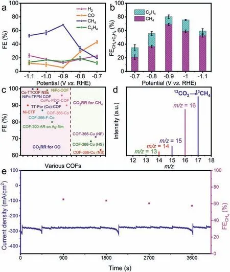
Fig.4.Electrocatalytic performances.(a) Faradaic efficiencies of COF-366-Cu (HS)at different applied potentials.(b) FECH4+ C2H4 of COF-366-Cu (HS) at different potentials (−0.7 V to −1.1 V).(c) A summary of electrocatalytic performances of the literature reported materials and COF-366-Cu,COF-366-Cu (HS),COF-366-Cu (NF)and COF-366-Cu (NS).(d) The mass spectra of 13CH4 recorded under 13CO2 atmosphere.(e)Durability test of COF-366-Cu (HS) at the potential of −0.9 V vs. RHE.
Moreover,the electrochemical properties of COF-366-Cu (HS)obtained from different addition amounts of Ani have been investigated.With the addition of 3 μL Ani,it gives a FECH4of 61.1%and FEC2H4of 3.9% at −0.9 V with a current density of −269.3 mA/cm2(Fig.S40 in Supporting information).When the amount is increased to 10 μL (FECH4,67.0%;FEC2H4,12.5%,−292.1 mA/cm2) or 30 μL (FECH4,66.6%;FEC2H4,11.6%;−285.7 mA/cm2) (Figs.S41 and S42 in Supporting information).When it increases to 50 μL,it gives slightly lower FECH4of 64.1% and FEC2H4of 6.9% with a current density of −280.7 mA/cm2,which might be attributed to the morphology change (Fig.S43 in Supporting information).Therefore,we select the sample with 5 μL Ani addition with the best performance (FECH4,68.2%;FEC2H4,14.6%,−0.9 V) as the target one to further investigate other properties.For COF-366-Cu (NF),it gives a FECH4of 71.0% and a FEC2H4of 16.6% at −0.9 V with a current density of −350.8 mA/cm2(Fig.S35).When the additive is TETA,it can result in nanofiber morphology and the FECH4is 69.2% and a FEC2H4of 10.8% at −0.9 V with a current density of −325.4 mA/cm2(Fig.S44 in Supporting information).For COF-366-Cu (NS),it has a FECH4of 64.2% at −0.9 V and a FEC2H4of 5.6% with a current density of −276.0 mA/cm2(Fig.S36).For the samples that possess nanosheet morphology obtained from modulators of NH4X (X=F,Cl and Br),their CO2RR performances have also been evaluated and compared.When the modulator is NH4Cl or NH4Br,they can result in nanosheet morphology.The samples obtained from NH4Cl(FECH4,57.0% and FEC2H4,6.6%,−0.9 V) and NH4Br (FECH4,61.3%and FEC2H4,10.0%,−0.9 V) as the modulator display poorer performance than that of NH4F (FECH4,64.2%;FEC2H4,5.6%,−0.9 V) (Figs.S45 and S46 in Supporting information).Therefore,we select samples with the optimal modulator that possess best performances for further investigation.
To further support the activity of COF-366-Cu,COF-366-Cu(HS),COF-366-Cu (NF) and COF-366-Cu (NS),partial current densities of H2,CO,CH4and C2H4at different potentials are calculated (Figs.S33–S36).COF-366-Cu,COF-366-Cu (HS),COF-366-Cu(NF) and COF-366-Cu (NS) present partial CH4current density of−105.2 mA/cm2,−194.7 mA/cm2,−248.6 mA/cm2,−177.3 mA/cm2at −0.9 V,respectively (Fig.3e).The results show that the partial current densities of COF-366-Cu (HS) are almost twice than that of COF-366-Cu (Fig.3e).To estimate the electrochemical active surface area (ECSA) and discuss the potential influence factors,electrochemical double-layer capacitance (Cdl) has been calculated and analyzed.The results show that COF-366-Cu (HS) (2.07 mF/cm2),COF-366-Cu (NF) (2.73 mF/cm2) and COF-366-Cu (NS)(1.20 mF/cm2) all exhibit higherCdlvalue than that of COF-366-Cu (0.78 mF/cm2) (Fig.3f and Fig.S47 in Supporting information).These results suggest that the samples obtained from morphology control would provide more active sites to contact with the electrolyte and facilitate the electrocatalytic CO2RR process.
To detect the carbon source of electrochemical CO2RR products,an isotopic experiment that utilizing13CO2as substrate performed under similar reaction conditions has been conducted.Taking COF-366-Cu (HS) as an example,the products are analyzed by GC and mass spectra.The peaks atm/z=17,29 and 30 are assigned to13CH4,13CO and13C2H4,respectively (Fig.4d and Fig.S48 in Supporting information),which indicate the carbon sources of CH4,CO and C2H4indeed derive from the CO2.In addition,electrochemical impedance spectroscopy (EIS) measurement has been carried out to probe the electrocatalytic kinetics on the electrode/electrolyte surface.Interestingly,the charge transfer resistance of COF-366-Cu,COF-366-Cu (HS),COF-366-Cu (NF) and COF-366-Cu (NS) are calculated to be 12.27Ω,6.51Ω,5.68Ωand 9.83Ω,respectively (Fig.S49 in Supporting information).This result shows that COF-366-Cu (HS),COF-366-Cu (NF) and COF-366-Cu (NS) can provide faster electron transfer from the catalyst surface to the reactant (i.e.,CO2)than that of COF-366-Cu,thus eventually resulting in largely enhanced activity and selectivity.
Long-time durability is important to evaluate the performance in electrocatalytic CO2RR as it determines the lifetime of electrocatalysts.To test it,the longtime durability test of COF-366-Cu(HS) has been performed at −0.9 V by chronoamperometric curves.After 3600 s,the corresponding FECH4can be maintained to be higher than 57.5% and the current density can be remained at about −276.1 mA/cm2(Fig.4e).After the electrocatalytic test,the PXRD pattern of COF-366-Cu (HS) matches well with the sample before test (Fig.S50 in Supporting information).For the ICP-MS results,the Cu detected in the test is below the detection limit (Table S2 in Supporting information).Besides,the morphology characterization of COF-366-Cu (HS) after electrochemical experiment presents remained hollow sphere morphology as supported by the SEM and TEM results (Fig.S51 in Supporting information).Moreover,the XPS tests before and after CO2RR show that the surface electronic state and elemental composition of the electronic structure remain unchanged (Fig.S5),and there are no Cu and Cu(I) observed,which certifies the high stability during the electrochemical CO2RR process.
In summary,we have designed three kinds of porphyrin COFs based multi-dimensional nanostructures (i.e.,hollow spheres,nanosheets and nanofibers) through a modulator tuning strategy.Interestingly,different modulators can induce the self-assembly of different morphologies and the formation processes have been investigated by the time-interval experiments.The obtained multidimensional nanostructures possess large surface area,high stability,CO2adsorption properties and tremendous Cu-N4sites that enable efficient CO2RR to CH4.Specifically,these sample with multidimensional morphology all exhibit superior FECH4(hollow sphere,68.2%,−0.9 V;nanosheet,64.2%,−0.9 V and nanofiber,71.0%,−0.9 V) to pristine COF-366-Cu (43.0%,−0.9 V).Noteworthy,the FECH4of COF-366-Cu (HS) keeps higher than 52.4% over a wide potential range from −0.9 V to −1.1 V and the achieved FECH4+C2H4(82.8%,−0.9 V) is superior to most of reported COFs and copper-based electrocatalysts.The morphology-controlled strategy for the design of COFs based nanostructures with tunable morphology that can be applied in efficient CO2RR to CH4would expedite the development of COFs in this field.
Declaration of competing interest
The authors declare that they have no known competing financial interests or personal relationships that could have appeared to influence the work reported in this paper.
Acknowledgments
This work was financially supported by the National Natural Science Foundation of China (NSFC,Nos.21871141,21871142,21901122,22071109 and 92061101);the Natural Science Research of Jiangsu Higher Education Institutions of China (No.19KJB150011) and Project funded by China Postdoctoral Science Foundation (Nos.2018M630572 and 2019M651873);Priority Academic Program Development of Jiangsu Higher Education Institutions and the Foundation of Jiangsu Collaborative Innovation Center of Biomedical Functional Materials.
Supplementary materials
Supplementary material associated with this article can be found,in the online version,at doi:10.1016/j.cclet.2021.08.063.
 Chinese Chemical Letters2022年3期
- Chinese Chemical Letters的其它文章
- Direct catalytic nitrogen oxide removal using thermal,electrical or solar energy
- Construction and applications of DNA-based nanomaterials in cancer therapy
- Recent research progress of bimetallic phosphides-based nanomaterials as cocatalyst for photocatalytic hydrogen evolution
- Nanostructured materials with localized surface plasmon resonance for photocatalysis
- Recent progress of Pd/zeolite as passive NOx adsorber: Adsorption chemistry,structure-performance relationships,challenges and prospects
- Microfluidic methods for cell separation and subsequent analysis