Dual⁃Polarized RIS⁃Based STBC Transmission with Polarization Coupling Analysis
ZHOU Mingyong,CHEN Xiangyu,TANG Wankai ,KE Jun Chen ,JIN Shi ,CHENG Qiang ,CUI Tie Jun
(1.National Mobile Communications Research Laboratory,Southeast University,Nanjing 210096,China;2.State Key Laboratory of Millimeter Waves,Southeast University,Nanjing 210096,China)
Abstract:The rapid development of the reconfigurable intelligent surface (RIS)technology has given rise to a new paradigm of wireless trans‑mitters.At present,most research works on RIS-based transmitters focus on single-polarized RISs.In this paper,we propose a dual-polarized RIS-based transmitter,which realizes 4-transmit space-time block coding (STBC) transmission by properly partitioning RIS’s unit cells and utilizing the degree of freedom of polarization.The proposed scheme is evaluated through a prototype system that utilizes a fabricated dualpolarized phase-adjustable RIS.In particular,the polarization coupling phenomenon in each unit cell of the employed dual-polarized RIS is modeled and analyzed.The experimental results are in good agreement with the theoretical modeling and analysis results,and an initial re‑search effort is made on characterizing the polarization coupling property in the dual-polarized RIS.
Keywords:reconfigurable intelligent surface;space-time coding;dual polarization;coupling modeling;prototyping
1 Introduction
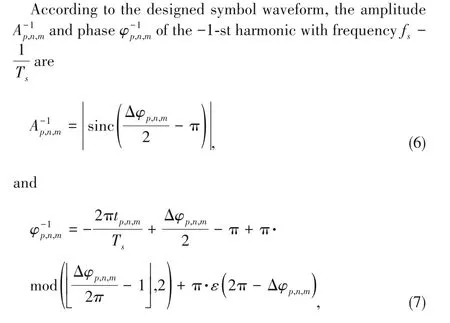
With the commercialization of the fifth-generation(5G) mobile communication networks,the spec‑trum resources of millimeter wave band are gradu‑ally developed and utilized,and base stations(BSs) also begin to assemble massive multiple-input multipleoutput (MIMO) hardware and corresponding algorithms to pro‑vide better communication services[1-2].However,the an‑tenna array equipped with massive MIMO needs numerous ra‑dio frequency (RF) chains,which leads to high hardware costs,high energy consumption,high system complexity,and severe heat dissipation issues.These problems will become more serious in the sixth-generation (6G) mobile communica‑tion networks.The emergence of reconfigurable intelligent surfaces (RISs) in recent years may bring new solutions to these challenges[3-6].
The concept of digital coding and programmable metamateri‑als was first proposed in 2014[7].When applied to the field of wireless communications,the reconfigurable two-dimensional metasurfaces are usually called RISs,which are composed of many sub-wavelength unit cells[8-9].Each unit cell of a RIS can be configured to change its response to electromagnetic (EM)waves,so as to adjust and control EM wave parameters,such as the amplitude or phase,during the interaction between the unit cell and EM waves[10].A RIS is usually controlled by a field pro‑grammable gate array(FPGA)for real-time configuration to real‑ize the regulation and control of EM waves.
The research on RISs can be categorized into two major ap‑plication directions:the RIS-based transmitter and the RISbased relay.The RIS-based transmitter focuses on using RIS to regulate EM wave parameters,thus modulating information on EM waves.The RIS-based relay focuses on improving the channel quality through RISs,thus enhancing the signal strength and coverage performance[11-12].
There have been some prior research works on RIS-based transmitters.The authors of Ref]13] proposed a binary fre‑quency shift keying (BFSK) wireless communication system based on RIS,and the authors of Refs]14-16] realized sev‑eral RIS-based phase shift keying (PSK) transmission proto‑types.A RIS-based space-time transmission system was pro‑posed and implemented in Ref]17].However,previous re‑search on RIS-based transmitters was based on singlepolarized RISs,and the potential of RISs in the degree of free‑dom of polarization was not fully exploited.Recently,some fabricated RISs have been able to realize EM control in differ‑ent polarization directions[18].The authors of Ref]19] realized MIMO transmission based on a dual-polarized RIS,and the authors of Ref]20] proposed a communication system as‑sisted by a dual-polarized RIS.
In this paper,a 4-transmit space-time block coding (STBC)transmission system based on a dual-polarized RIS is pro‑posed and validated by experiments.In this system,a 4-trans‑mit space-time transmitter is realized by utilizing the degree of freedom of the RIS’s polarization.In addition,the polariza‑tion coupling phenomenon in the unit cell of the employed dual-polarized RIS is modeled and analyzed.
The rest of the paper is organized as follows.Section 2 intro‑duces the system model of the proposed 4-transmit RIS-based STBC transmission system.Section 3 gives the design details of the proposed system and Section 4 analyzes the bit error rate (BER) performance by considering polarization coupling interference in each unit cell.The prototype system and ex‑perimental measurement results are shown in Section 5.Sec‑tion 6 summarizes the paper.
2 System Model
Fig.1 shows the diagram of the 4-transmit space-time trans‑mission system based on a dual-polarized RIS.The transmitter consists of a digital baseband module,a dual-polarized phaseadjustable RIS and a radio frequency (RF) signal source.The receiver hasKreceiving antennas and a baseband processing module.The dual-polarized RIS hasNrows andMcolumns of unit cells,and each unit cell can realize the phase regulation in horizontal polarization and vertical polarization,respec‑tively.MandNare assumed to be even.The single tone car‑rier signal incident on the dual-polarized RIS is emitted by a feed antenna.
The incident signal power of each unit cell ispin both hori‑zontal and vertical polarization.Letprepresent the polarization direction,p=1 means vertical polarization,andp=0 means horizontal polarization.The unit cell in rownand columnmis denoted asUn,m.Ap,n,mandφp,n,mrepresent the reflection ampli‑tude and reflection phase shift ofUn,min polarizationp,and the channel fromUn,mto thek⁃th receiving antenna in polarizationpis denoted as.Then the signal received fromUn,mby thek⁃th receiving antenna in polarizationpis.It can be noted thatxp,n,m=Ap,n,meφp,n,mrep‑resents the data symbol modulated byUn,monto the single-tone carrier in polarizationpand we have.
Then×munit cells of the RIS can be divided into left and right parts in horizontal polarization,and upper and lower parts in vertical polarization.As shown in Fig.1,the horizon‑tal left part is marked as the yellow part,the horizontal right part is marked as the orange part,the vertical upper part is marked as the blue part,and the vertical lower part is marked as the indigo part.Then the wireless channel from the yellow part to thek ⁃th receiving antenna is denoted ashk,1=and accordingly,stand for the wireless channel between the orange part and thek⁃th receiving an‑tenna,the wireless channel between the blue part and thek⁃th receiving antenna,and the wireless channel between the indigo part and thek⁃th receiving antenna,respectively.Therefore,the channel parameters from the 4-transmit space-time dualpolarized RIS-based transmitter to the receiver can be written as
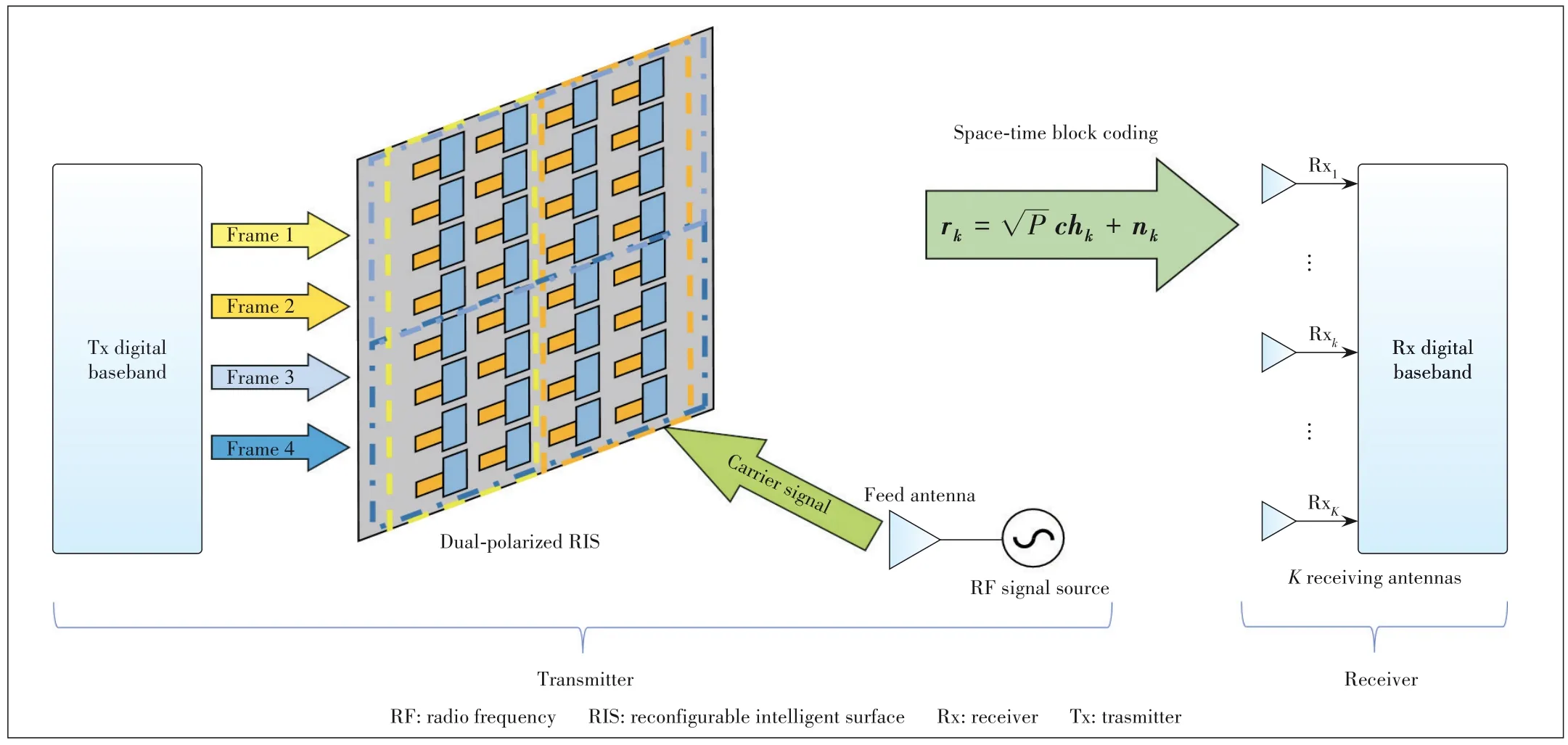
▲Figure 1.Proposed 4-transmit space-time wireless communication system based on a dual-polarized RIS

The STBC matrix is designed as[21]:

wherec1,c2,andc3are three transmitted baseband symbols.The coding matrix encodes three data streams into four data frames and transmits them in four time slots as a period.The received signals of thek⁃th receiving antenna in the corre‑sponding time slot of coding are

whererk,nkandhkare the received signal vector,the noise vector,and the wireless channel vector of thek⁃th antenna,re‑spectively.
Eq.(4) reveals the basic principle of the 4-transmit spacetime transmission system based on the dual-polarized RIS.It is consistent with the traditional space-time transmission sys‑tem in form but different in hardware composition and channel structure.The proposed system modulates the information onto the carrier in the process of reflecting the signal through the dual-polarized RIS,which does not require the conven‑tional RF chains.Therefore,the 4-transmit space-time trans‑mission scheme based on the dual-polarized RIS provides a new space-time transmitter design with the advantages of low hardware costs and complexity.
3 Design of 4-Transmit Space-Time Trans⁃mission Based on Dual-Polarized RIS
This section will introduce in detail the scheme of a 4-trans‑mit space-time transmission wireless communication system based on the dual-polarized RIS,including the design of wave‑forms,the wireless frame structure,and the receiver combin‑ing method.
3.1 Waveform Design of Transmitted Symbols
Space-time coding needs to realize the complex conjugate operation of the transmitted symbols.However,the amplitude response and phase shift of the dual-polarized phaseadjustable RIS used in this paper are coupled.If the phase of RIS’s unit cell is directly regulated,the envelope of the trans‑mitted symbol will be non-constant and the complex conjugate operation of the symbol cannot be realized.Therefore,the non‑linear modulation technology is employed in this work[17].
During one symbol period,the transmitted symbol wave‑form is designed as

whereTsis the symbol period,tp,n,m∈[0,Ts] is the circular time delay,and the symbol phase decreases linearly withas the slope.
3.2 Wireless Frame Structure Design

▲Figure 2.Frame structure design of 4-transmit space-time transmis⁃sion system based on dual-polarized RIS
The frame structure is designed as shown in Fig.2 for 4-transmit space-time coding transmission based on the dualpolarized RIS.It includes one synchronization subframe,one pilot subframe and 60 data subframes.The pilots of four trans‑mitting data frames are orthogonal in time for ease of channel estimation.The four data frames are transmitted by the four parts of the RIS respectively.Each pilot subframe includes 32 Binary Phase Shift Keying (BPSK) symbols.There are 64 space-time coded 16-quadrature amplitude modulation (QAM)symbols in each data subframe,and all data symbols are based on the previously described waveform.11 520 (4×60×64×3/4=11 520)data bits are transmitted per frame duration.
3.3 Combining Scheme of Receiver
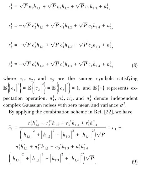
When the receiver has only one receiving antenna (K=1),we have
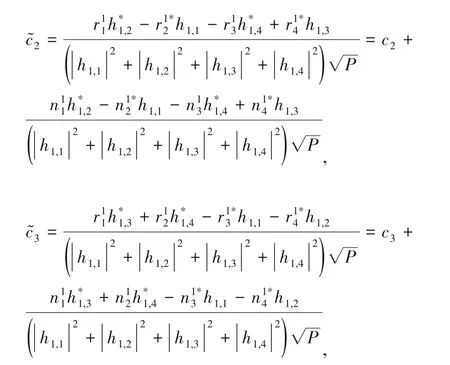

Similarly,when there are two receiving antennas,according to the combining scheme in Ref]22],there are

Therefore,when there are two receiving antennas at the re‑ceiver,the SNR of stream 1,stream 2 and stream 3 is

From the two SNR formulas of Eqs.(10) and (14),it can be found that the 4-transmit space-time transmission scheme based on the dual-polarized RIS proposed in this paper is basi‑cally consistent with the traditional space-time transmission system.The same diversity order and diversity gain can be ob‑tained.
4 Polarization Coupling Modeling and BER Performance Analysis
4.1 Polarization Coupling Modeling for Dual-Polarized RIS
The authors of Ref]19] have preliminarily revealed the phenomenon of polarization coupling in the unit cell of the dual-polarized RIS.Based on the coupling constellation and the coupling voltage of the unit cell given in Ref]19],a linear symbolic coupling model is proposed as follows to analyze the polarization coupling phenomenon in the 4-transmit space-time transmission based on the dualpolarized RIS.
Theorem 1.The coupling model between two polarization directions of the unit cellUn,mcan be written as

whereaandbare the coefficients coupled to the horizontal and vertical polarization,x0,n,mandx1,n,mare the original trans‑mitted symbols in horizontal and vertical polarization,andare the actual transmitted symbols in horizon‑tal and vertical polarization.
Theorem 1 reveals that the transmitted symbols of two polar‑ization directions are mutually coupled in one unit cell of the dual-polarized RIS.In particular,Theorem 1 indicates that the actual transmitted symbols are the linear combination of original transmitted symbols and coupled transmitted symbols from another polarization direction.
Based on the system model in Section 2,when the system operates normally and has no polarization coupling interfer‑ence,the signal received fromUn,mby thek-th receiving an‑tenna in polarizationpis.
According to Theorem 1,the signal that considers polariza‑tion coupling interference received fromUn,mby thek-th re‑ceiving antenna in polarizationpis,wherex1-p,n,mis the transmitted symbol in another polarization,andqis the coupling coefficient between unit cell’s control voltages for horizontal and vertical polariza‑tion directions.According to Ref]19],is the co‑efficient coupled to the horizontal polarization andq=b=is the coefficient coupled to the vertical polarization for the employed dual-polarized RIS.
4.2 BER Performance Without Polarization Coupling In⁃terference
For the sake of analysis,it is assumed that the wireless channel parameters (h1,1,h1,2,h1,3,h1,4,h2,1,h2,2,h2,3,h2,4) re‑main constant during transmission.Due to the standardly mapped 16-QAM with Gray coding and the traditional QAM demodulation method,the theoretical total BER of the 4-transmit space-time RIS-based transmission system can be expressed as[17,23]:
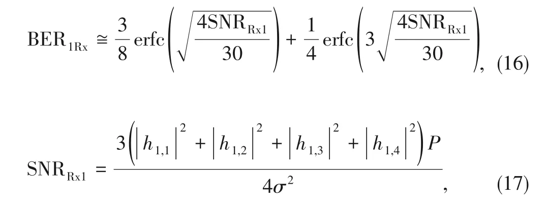
where erfc(·)is the complementary error function and SNRRx1is the received SNR for one receiving antenna.
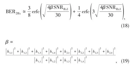
Similarly,the system BER with two receiving antennas is[17,23]:whereβis the diversity gain obtained when the receiver has two receiving antennas.
4.3 BER Performance Considering Polarization Coupling Interference
Take the horizontal polarization as an example,when the symbolsX1,X2,X3andX4are respectively transmitted by the yellow,orange,blue and indigo parts of RIS as shown in Fig.1 in a certain time slot,the signal received by thek-th receiving antenna in horizontal polarization from the yellow part is

are the channels from the upper region and lower region of the yellow part to thek-th receiving antenna in horizontal polarization.
And the signal received by thek-th receiving antenna in horizontal polarization from the orange part is

For thek-th receiving antenna,the received signal in a cer‑tain time slot is


When the RIS-based transmitter transmits data according to the STBC matrixcof Eq.(2),we letand there is

Eq.(27) gives the system model that considers polarization coupling interference,and the influence of the proposed sym‑bolic coupling model is mainly reflected in the STBC matrixccouple.Then the BER performance of the system is discussed as follows.
Proposition 1.When considering polarization coupling in‑terference and there is only one receiving antenna at the re‑ceiver,the upper bound of system BER can be written as

where SINR1Rxis the signal-to-interference plus noise ratio(SINR)of the data stream with a single receiving antenna.
Proof:See Appendix A.
Eq.(28) in Proposition 1 and Eq.(16) have the same struc‑ture,but the difference is that Eq.(28) is related to SINR due to the polarization coupling interference while Eq.(16) is just related to SNR.Proposition 1 reveals that the BER of the pro‑posed system is not only influenced by the SNR of the system,but also by polarization coupling interference.When the inter‑ference terms in SINR are 0,Eq.(28) will degenerate into Eq.(16).However,because of the interference terms,the SINR of the system will decrease,which leads to the deterioration of the system BER performance and this is consistent with the in‑tuition.
For the case of two receiving antennas,we can get Proposi‑tion 2 as follows.
Proposition 2:When considering polarization coupling in‑terference and there are two receiving antennas at the re‑ceiver,the upper bound of system BER can be written as
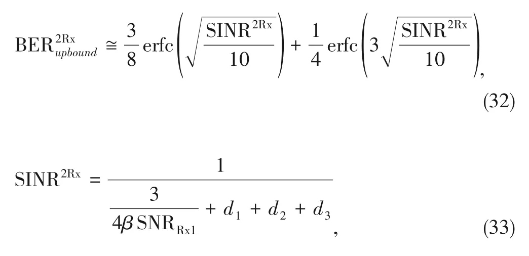
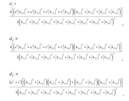
where SINR2Rxis the SINR of system data stream with two re‑ceiving antennas and

Proof:See Appendix B.
According to Proposition 2,diversity gainβexists in both SNR terms and interference terms (d1,d2,d3),which means that even if more receiving antennas are equipped,polariza‑tion coupling interference will still prominently affect the BER performance of the system.Besides,Eqs.(28) and (29)also indicate that if we want to improve the BER performance,we need to reduce coupling coefficientsuandv,which leads to less polarization coupling interference.And that puts for‑ward new requirements for the design of the unit cell of a dualpolarized RIS.In the following section,we will validate the proposed symbolic polarization coupling model by the experi‑mental measurements based on our prototype system.
5 Implementation of 4-Transmit Space-Time Transmission Based on Dual-Polarized RIS
5.1 Prototype Setup
Fig.3 shows our prototype of 4-transmit space-time trans‑mission based on the dual-polarized RIS.The system consists of a 4-transmit space-time RIS-based transmitter and a tradi‑tional receiver.The 4-transmit space-time transmitter is com‑posed of a dual-polarized phase-adjustable RIS that is con‑troled by a PXIe platform,a horn antenna and an RF signal source.The traditional receiver consists of two receiving an‑tennas and a software defined radio(SDR)platform.
The dual-polarized RIS is a phase programmable metasur‑face with an operating frequency of 2.7 GHz.There are 144(12×12) unit cells in total,and each unit cell has two pairs of metal patches and two varactor diodes are connected across it.The bias voltage is applied to the varactor diodes through the corresponding metal patches to control the reflection coeffi‑cient of the unit cell in two polarization directions[18-19].The RIS fabricated with varactors can continuously regulate the phase,which makes the transmission waveform design in Sec‑tion 4 achievable.
Specifically,three bit streams are generated by the PXIe platform,mapped into three 16-QAM symbol streams,and en‑coded by the STBC matrix to generate four baseband frames.The four frames are converted into four analog voltage signals by the digital-to-analog converters (DACs) of the PXIe plat‑form and loaded on the varactors of the corresponding RIS’s unit cells respectively.When the 2.7 GHz single tone carrier generated by the RF signal source is transmitted and irradi‑ated on the RIS through the horn antenna,the dual-polarized RIS modulates four data frames onto the carrier.The transmit‑ting horn antenna is placed at an inclination of 45° so that there are carrier components in both horizontal and vertical polarization directions.The receiver receives the signal through two single polarization antennas inclined at 45°.The received signal is down converted and sampled on the SDR platform,and the corresponding baseband data symbols are then decoded and demodulated.

▲Figure 3.Prototype of 4-transmit space-time transmission based on dual-polarized RIS
5.2 Experimental Results
As shown in Fig.3,the 4-transmit space-time transmission system based on the dual-polarized RIS can successfully real‑ize data transmission.The prototype is in an indoor environ‑ment with a transmission distance of about 1.5 m.When the symbol rate of the system is 2.5 million symbol/s,the transmis‑sion rate can reach 7.5 Mbit/s,which is determined by the ad‑opted space-time coding scheme.It can be seen from Fig.3 that the constellations of three data streams at the receiver can be well recovered.By adjusting the transmission power to change the received SNR,the BER performance is recorded simultaneously.The measurement results are shown in Fig.4.In Fig.4,the blue line is the theoretical BER curve without polarization coupling interference,the red line is the upper bound of the theoretical BER considering polarization cou‑pling interference,and the orange line is the actual measured BER curve.It can be seen that the measured BER is obvi‑ously worse than the theoretical one without polarization cou‑pling interference.This is because the control voltages regulat‑ing the unit cell’s phase in different polarization directions are coupled[19],which makes the four data frames doped with each other in the transmission process,resulting in additional interference and degradation of the BER performance of the actual system.Fig.4 also shows that the theoretical BER up‑per bounds given in Eqs.(28) and (29) are in good agreement with the measured curve,which validates our proposed linear symbol polarization coupling model for the dual-polarized RIS.
The above results indicate that the 4-transmit space-time transmission scheme based on the dual-polarized phaseadjustable RIS is feasible,but the mutual coupling of control voltages of the unit cell for different polarization directions will degrade the system performance.This enlightens that the polarization isolation performance should be carefully consid‑ered when designing dual-polarized RISs,and it is worth fur‑ther exploring in the future.
6 Conclusions
In this paper,a 4-transmit space-time transmission scheme based on the dual-polarized RIS is proposed.The prototype system based on a dual-polarized phase-adjustable RIS can transmit data over the air at a rate of 7.5 Mbit/s,which verifies the feasibility of the proposed scheme.In particular,a simple linear symbolic polarization coupling model is proposed for theoretical analysis,and the BER performance upper bound of the system is given.The measured curves are in good agree‑ment with the theoretical ones,which proves the effectiveness of the proposed model and scheme.In general,a multitransmit space-time transmitter based on the dual-polarized RIS is a promising scheme,which can flexibly build different space-time transmission systems to satisfy the transmission re‑quirements with low hardware complexity and cost.
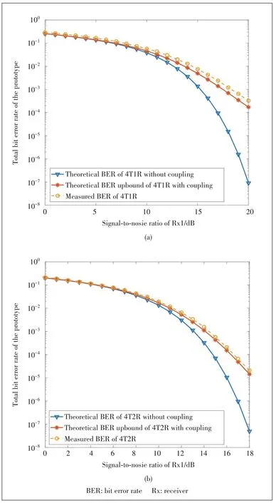
▲Figure 4.Comparison of system theoretical and measured BER-SNR performance:(a)one receiving antenna and(b)two receiving antennas
Appendix A
Proof of Proposition 1
The STBC matrix considering polarization coupling interfer‑ence is shown in Eq.(26).WhenK=1,which means that the receiver has only one receiving antenna,it can be obtained from Eq.(27)that




Appendix B
Proof of Proposition 2
WhenK=2,the received signals on the second receiving an‑tenna can be obtained from Eq.(27):

According to Ref]22],for two receiving antennas,there are the following combination formulas:
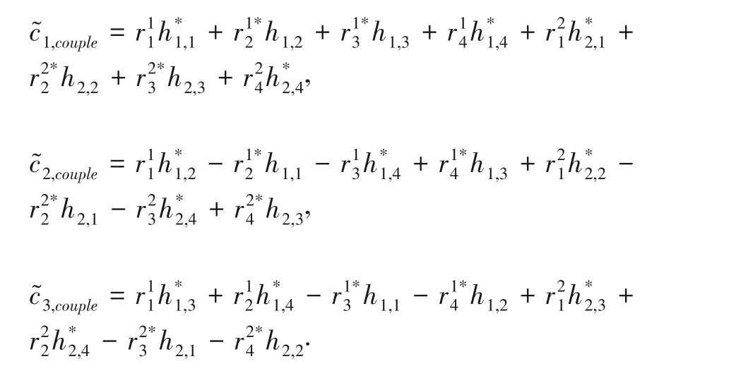
Since the form and structure of the received signals of the two antennas are consistent,the signal processing of the two receiving antennas is consistent in the combination formula.Therefore,it is easy to obtain


Then we have
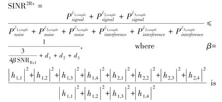
the diversity gain and
- ZTE Communications的其它文章
- Metric Learning for Semantic⁃Based Clothes Retrieval
- RIS:Spatial⁃Wideband Effect Analysis and Off⁃Grid Channel Estimation
- Markovian Cascaded Channel Estimation for RIS Aided Massive MIMO Using 1⁃Bit ADCs and Oversampling
- Resource Allocation for Two⁃Tier RIS⁃Assisted Heterogeneous NOMA Networks
- IRS⁃Enabled Spectrum Sharing:Interference Modeling,Channel Estimation and Robust Passive Beamforming
- Recent Developments of Transmissive Reconfigurable Intelligent Surfaces:A Review

