
Recent Developments on Damage and Fracture of Thin-Walled Complex Components Produced by Spinning
2022-03-12 13:29ZHANMeiZENGXiangJIANGZeminFANXiaoguangLIHongweiGAOPengfei
上海航天 2022年1期
ZHAN Mei,ZENG Xiang,JIANG Zemin,FAN Xiaoguang,LI Hongwei,GAO Pengfei
(1.Shaanxi Key Laboratory of High‑Performance Precision Forming Technology and Equipment,Northwestern Polytechnical University,Xi’an 710072,Shaanxi China;2.State Key Laboratory of Solidification Processing,School of Materials Science and Engineering,Northwestern Polytechnical University,Xi’an 710072,Shaanxi China;3.Shanghai Academy of Spaceflight Technology,Shanghai 201109,China)
Abstract:The spinning technique has been widely used in the manufacture of aerospace thin-walled axisymmetric components because of its excellent formability.Damage and fracture,as the important defects that often occur and must be avoided in the forming and service stages of components,have attracted much attention of researchers.In this paper,the fracture behavior and laws of spinning components such as conical parts,tubular parts,and components with inner ribs are summarized,the typical coupled and uncoupled ductile fracture models are introduced,and their applications in spinning are analyzed.Meanwhile,the recent developments on the modified ductile fracture model in analyzing damage and fracture mechanisms of spinning are emphatically introduced.The results could provide guidance for the selection and establishment of appropriate ductile fracture models in the finite element simulation for the accurate prediction and analysis of fracture moment,location,form,damage mechanism,and evolution law,and help the development of precision spinning techniques for high-performance thin-walled complex components.
Key words:spinning;fracture behavior;damage mechanism;fracture model;thin-walled component
0 Introduction
As an advanced continuous local loading forming technology,spinning owns the advantages of high forming precision and good forming performance.Thus,it is the main manufacture method for axisymmetric components.During spinning,the workpiece rotates with the spindle of a spinning machine in the circumferential direction,while the spinning rollers move along the spindle or the generatrix of the conical part after the rollers reach the set reduction or position.According to the wall thickness variation of formed parts,the spinning technique can be classified into power spinning and conventional spinning.The power spinning mainly includes shear spinning of conical parts and flow spinning of tubular parts.
In the past decades,lots of studies have been carried out on spinning techniquesand spinning products have been widely applied in civil and mili‑tary industries.Furthermore,in recent 20 years,with the increasing demands and requirements for high-performance lightweight components in the aerospace field,scholars began to pay attention to flow spinning of components with inner ribs,e.g.,thin-walled components with longitudinal inner ribs,thin-walled components with transverse in‑ner ribs,and components with complex specialshaped inner ribs.Spinning is a complex loading process with multi-parameters and multi-constraints of dies,which has strong nonlinearity on the materi‑al,geometry,and boundary condition.During the forming process,the material undergoes repeated loading and unloading,and thus it is easy to produce many forming defects difficult to be predicted.Frac‑ture is one of the most common and important form‑ing defects in spinning.Compared with the high-cost experimental research,finite element simulation has significant advantages in presenting the law of dam‑age evolution in real time and revealing the damage and fracture mechanisms.Therefore,it has become an indispensable means for the research and analysis on damage and fracture.
Therefore,in this paper,the damage and frac‑ture behavior and laws of spinning of conical parts,tubular parts,and components with inner ribs are summarized.Meanwhile,the typical coupled and un‑coupled ductile fracture models are introduced,and their applications in spinning are analyzed,so as to provide guidance for the development of accurate spinning techniques of high-performance thin-walled complex components.
1 Damage and fracture behavior and laws of spinning forming
1.1 Shear spinning of conical parts
Conical parts are extensively demanded in aero‑space and weapon equipment,e.g.,advanced air‑crafts,rockets,and missiles.As mentioned before,the forming of conical parts mainly belongs to shear spinning,and the change of the theoretical formed wall thickness()of the formed part conforms to the Sin law(=sin),as shown in Fig.1(a).When the wall thickness()of the formed part is greater thansin,it is called positive deviation.When the wall thickness()of the formed part is equal tosin,it is called zero deviation.Otherwise,it belongs to nega‑tive deviation.The initial circular blank becomes a thin-walled conical part after multi-pass spinning with different roller trajectories,as shown in Fig.1(b).For the requirements of practical application,the coni‑cal part usually consists of curved surfaces with differ‑ent curvatures,and the typical conical part with com‑plex curved surfaces is shown in Fig.1(c).It is main‑ly composed of spherical surface,conical surface,and ellipsoidal surface,which is a large thin-walled dome applied to the rocket storage tank.

Fig.1 Schematic diagram and experimental equipment of shear spinning of the conical part with curved surface[18-19]
In view of the geometric structure of thin-walled conical parts and the complex spinning trajectories,damage and fracture are prone to occur during the forming of these parts.ZHAN et al.found that the fracture occurred in the middle position of the conical part along the circumferential and radial directions during shear spinning,owing to the severe shear and tension deformation,as shown in Fig.2(a).LI et al.found that fracture occurred near the end forming time of the 2219 aluminium alloy tank dome via shear spinning,as shown in Fig.2(b).

Fig.2 Fractured aluminium alloy spun conical parts
LING et al.found that the work hardening ef‑fect was exacerbated during the multi-pass drawing spinning at room temperature,resulting in the occur‑rence of fracture at the mouth of the Haynes230 su‑peralloy component.WANG et al.found that if the intermediate pass heat treatment was not adopted,fracture would occur in the Ti2AlNb based alloy component during the second pass shear spinning.MORI et al.used hot shear spinning to form the cast aluminium alloy parts,and found that reducing the feed ratio and increasing the fillet radius of the roll‑er were beneficial to reduce the surface fracture at the corner of mandrel.Besides,increasing the forming temperature was an effective way to avoid fracture.
1.2 Flow spinning of tubular parts
According to whether the feed direction of the roller is consistent with the material flow direction during the forming process or not,the flow spinning(also named as flow forming)of tubular parts can be classified into forward spinning and reverse spinning.The schematic diagram is shown in Fig.3(a).In recent years,with the increasing demand for lightweight and high-strength components in the aerospace field,e.g.,titanium alloy components,flow spinning techniques combined with the thermal assisted process have been used to manufacture the key components such as the shell,nozzle,and storage tank of rocket engine and the annular cylinder and lunar rover parts of aircrafts.In order to realize a large wall thickness reduction rate,multi-pass spinning techniques have often been used for hard-todeform materials,as shown in Fig.3(b).During flow spinning,severe plastic deformation effectively refines the grains so as to improve the mechanical properties of the formed parts,as shown in Fig.3(c),Fig.3(d),and Fig.3(e).
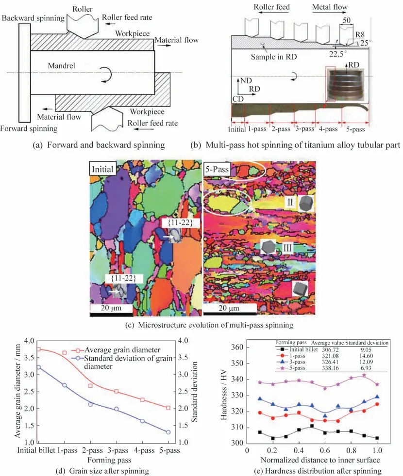
Fig.3 Schematic diagrams of flow forming and evolution law of microstructure and properties of spun tubular parts[26-27]
During flow spinning of tubular parts,damage and fracture defects are easy to occur in hard-to-de‑form materials or materials with poor plasticity at room temperature under a large wall thickness thin‑ning rate or other unreasonable process parameters.GUOstudied the rolling-spinning forming of TA15 titanium alloy tubular parts.He found that when the initial spinning temperature was 800 °C,the feed ra‑tio was 1 mm/rev,and the roller fillet radius was 10 mm,while when the wall thickness thinning rate reached 71.2%,fracture would occur,as shown in Fig.4(a).In addition,the wall thickness reduction rate of the component could reach 86.7% in four pass‑es when the optimized forming parameters were used,i.e.,the initial spinning temperature of 850 °C,the feed ratio of 1.5 mm/rev,and the fillet radius of 25 mm.XU et al.studied the damage and fracture behavior of Ti-15-3 alloy parts spun at room tempera‑ture under different wall thickness thinning rates.The results showed that fracture originated on the inner surface of the formed parts under a small wall thick‑ness thinning rate(18.2%),and the formed part would be completely ruptured when the wall thickness reduction rate was too large(42.3%).Therefore,it can be concluded that the wall thickness reduction rate has an important effect on the damage and fracture in spinning.MA et al.used the spin‑nability test to determine the maximum wall thickness reduction rate of the tube.

Fig.4 Fractured spun tubular parts made of difficult-to-deform or poor plasticity materials
When the wall thickness thinning rate is too large at room temperature flow spinning,superalloy tubu‑lar parts are also easy to fracture.WANG et al.found that the deformation in the thickness direction of Haynes230 superalloy tubular billets was uneven during reverse spinning.Plastic deformation mainly acted on the outer layer material of the cylinder,and gradually expanded to the inner layer material with the deformation going on.The large shear strain at the outer layer was an important reason for fracture.LI et al.used multipass spinning to form GH3030 su‑peralloy tubular parts from initial blank workpieces,and found that fracture was more likely to occur at in‑appropriate roller trajectories,as shown in Fig.4(b),but the helical roller trajectory was conducive to the formation of target components.KUSS et al.found that the forming performance of 37MnSi5 steel pipes or bars was affected by the surface fracture defects during ball spinning,but could be improved by ad‑justing the wall thickness reduction and the axial feed‑ing speed of the roller.
Components with poor plasticity at room tem‑perature such as magnesium alloy components have been widely studied.JIN et al.found that when the temperature was too low(<420 °C),fracture would occur in the tubular billet(Mg-6Gd-4Y-0.5Zn-0.5Zr)during one pass or two passes hot spinning on ac‑count of the poor formability of magnesium alloy at low temperature,as shown in Fig.4(c).At exces‑sively high temperature(>460 °C),the tubular bil‑let would be broken due to over burning.The suit‑able forming temperature range was from 420 °C to 460 °C.Hot flow spinning was also employed by CAO et al.to manufacture AZ80 magnesium alloy tube.The tube could be formed without fracture at the spindle speed of 200 rev/min -400 rev/min,while the middle position of the tube was fractured when the spindle speed was too high(600 rev/min).When the feed ratio was too small(0.05 mm/rev)or too large(0.25 mm/rev),fracture also occurred.Therein,the suitable feed ratio range was from 0.07 mm/rev to 0.15 mm/rev.Thus,for materials with poor plasticity at room temperature,the pro‑cess parameters such as temperature and feed ratio have significant effects on the fracture behavior of the components.
In addition,DAVIDSON et al.studied the flow spinning of annealed AA6061 aluminum alloy tube.The results showed that uneven deformation was generated at a small wall thickness reduction rate in the initial stage.The large plastic deformation on the outer layer and the small plastic deformation on the inner layer of the tube resulted in fracture generat‑ed from the inner layer of the tube.In the final spin‑ning stage,the component was prone to sudden rup‑ture at the excessive wall thickness reduction rate.If the gap between the mandrel and the workpiece was too large,the opening end of the formed part was easy to fracture on account of diameter expansion.
1.3 Flow spinning of components with inner ribs
With the development of aerospace equipment towards high carry capacity and long service life,the requirements for high performance,lightweight,and high reliability of components rise continually.Therefore,the integrated manufacture techniques of components with inner ribs have attracted the attention of scholars,among which spinning is one of the most hopeful methods.The spinning of components with inner ribs usually adopts external spinning with rib grooves on the mandrel.The flow spinning forming principle and formed tubular parts with cross inner ribs are shown in Fig.5.During the flow spinning of tubular parts with cross inner ribs,with the rotation of the spindle and the axial motion of the roller,the material of the tubular billet is filled into the rib grooves under the continuous local loading of two symmetrically distributed rollers,so as to form the cross inner ribs.The material at the non-rib zone is under thinning deformation.The size and number of inner ribs can be adjusted by the size and number of the rib grooves on the mandrel.For the stiffened components,the risk of damage and fracture is exacerbated by the complex material flow and the effect factors such as material,processing,and mould parameters.

Fig.5 Schematic diagram and formed parts of flow spinning of tubular parts with cross inner ribs
The components with only one kind of inner ribs/teeth have also been investigated widely.XIA et al.studied the spinning of annealed 6061 aluminum alloy cup-shaped trapezoidal internal gear.The results showed that the surface fracture of the gear was caused by the poor fitability or the too short length of the workpiece,and the unreasonable process parame‑ters would cause the fracture of the tooth groove.XU et al.found that the internal gear broke at different positions with the change of the process parameters,i.e.,on the top of teeth,between the teeth,and on the internal teeth.Increasing the thickness thinning rate and workpiece thickness could improve the fill‑ing ability of the internal teeth,but the excessive in‑crease in the thickness thinning rate would lead to fracture.If the feed rate was slightly larger,the fill‑ing of the internal teeth was better,and the fracture could be avoided at the same time.Two typical de‑fects,i.e.,under-filling and fracture,could be con‑trolled by adjusting the process parameters.HUANG et al.formed Q235 steel cup-shaped parts with the internal and external teeth through multi-wheel plane‑tary spinning.They found that the external teeth were easy to fracture in the initial spinning stage,while the internal teeth were easy to fracture in the stable forming stage owing to the effect of the threedimensional(3D)tensile stress.
For the components with complex inner ribs,our team has conducted in-depth research on the damage and fracture behavior of 2219 aluminum al‑loy tubular parts with longitudinal and transverse in‑ner ribs(LTIRs).Under inappropriate processing and die parameters,multi-mode fracture behaviors occurred in the parts,such as the fracture in the nonrib zone and on the longitudinal inner ribs,as shown in Fig.6.In addition,ZHUfound that there was no fracture on the inner surface of the components with LTIRs,but fracture occurred on the outer sur‑face when the thinning rate was too large.Similarly,LIANGstudied the flow spinning of 5A06 alumi‑num alloy tubular parts with complex inner ribs,and found that different forms of fracture occurred during the spinning of parts such as the V-shaped fracture at longitudinal inner ribs and the vertical fracture per‑pendicular to the axis at the end of formed parts,but the V-shaped fracture turned to the vertical fracture at a large feed speed.Therefore,it can be concluded that the complex structure of components with internal teeth/ribs aggravates the complexity of frac‑ture location and types.

Fig.6 Multi-mode fracture of tubular parts with LTIRs
Fracture also occurs in some special-shaped parts during spinning.SHAO et al.used the external-internal composite spinning technique to form the Ω-shaped ring.They found that the end of the GH4169 thin plate was easy to fracture due to the sudden increase in the stress at room temperature,as shown in Fig.7(a).ZHAN et al.found that there was radial fracture in the LF2M aluminium alloy V-grooved wheel during splitting spinning,as shown in Fig.7(b).

Fig.7 Special spinning technique and fractured specialshaped spun parts
To sum up,during the shear spinning of conical parts and flow spinning of tubular parts and compo‑nents with inner ribs,fracture is easy to occur due to the effects of process parameters(such as the wall thickness thinning rate,the feed ratio,the forming temperature,the spinning pass,and the roller trajec‑tory)and geometric parameters of the roller and mould.The risk of fracture increases in the deforma‑tion of high strength and hard-to-deform materials and the materials with poor plasticity at room temper‑ature.Moreover,the fracture form and location of spinning are also complex.Because fracture is the fi‑nal failure of components,it may bring disastrous consequences in the practical engineering application,and the cost of experimental research is high.There‑fore,it is necessary to carry out finite element simula‑tion research,which can also be carried out to predict damage and fracture defects and analyze the damage and fracture mechanism and law.
2 Application of ductile fracture model in spinning
2.1 Coupled and uncoupled ductile fracture models
Ductile fracture usually begins with the nucleation of micro-void.With the increase in the strain,the voids gradually grow and coalesce,result‑ing in the eventual failure of the material.With the indepth analysis and quantification of ductile fracture,a large number of fracture criteria have been proposed and developed.According to whether the damage variables are coupled into the material constitutive equation,the fracture criteria are usually divided into coupled and uncoupled types.The Gurson-like mod‑eland the model based on the continuum damage mechanics(CDM)are the most widely applied cou‑pled fracture criteria.The former was first proposed by Gurson,and then modified by Tvergaard and Needleman to be the Gurson-Tvergaard-Needleman(GTN)model,as shown by


For the latter,the Lemaitre modelis the most widely used CDM model,and its incremental form is given by


The simplicity of the upcoupled fracture criteria makes them widely used in the engineering field.When voids begin to coalesce under the critical plastic strain,the material is considered to fail.The general form of the upcoupled fracture criteria is given by


In the uncoupled fracture models,the first prin‑cipal stress,the equivalent stress,the hydrostatic stress,the maximum shear stress,etc.are often thought as the determinants of fracture.For exam‑ple,the model proposed by CROCKROFT and LATHAM(C&L)suggests that the main reason for fracture is that the integral of the first principal stress along the plastic strain path reaches the damage threshold,while OH et al.considered that the equivalent stress is also an important factor for fracture,as shown by

whereandare the damage thresholds,andis the first principal stress.
2.2 Applicability of the ductile fracture model in spinning
In order to analyze the damage evolution law of components in spinning and predict the fracture posi‑tion and forming limit of spinning parts accurately,ductile fracture models are usually coupled into spin‑ning finite element models.At present,the studies on the damage and fracture in spinning through duc‑tile fracture models are mainly divided into two cate‑gories.One is to apply ductile fracture models to spin‑ning and investigate the applicability of the ductile fracture models in spinning.The other is to modify the existing damage models according to the deforma‑tion behavior of materials and the forming characteris‑tics of components so as to predict the evolution law of the damage and fracture in the spinning process more accurately.
LI et al.and ZHAN et al.compared the frac‑ture prediction of conical parts by different ductile fracture models,and found that all of the four crite‑ria,i.e.,FREUDENTHAL,C&L,OYANE,and modified Mohr-Coulomb criterion(MMC4),could predict the fracture position of the conical parts,but the deviation degrees between the damage value and the threshold were different.Among them,the deviation degree of the Oyane criterion was the smallest.Moreover,they introduced three methods to characterize the fracture behavior,i.e.,damage threshold,fracture strain,and fracture forming limit diagram,as shown in Fig.8.HUapplied the Le‑maitre model and the C&L criterion to fracture predic‑tion and forming limit analysis of splitting spinning,and found that the Lemaitre model predicted the radial fracture phenomenon of splitting spinning more accurately than the C&L criterion.MAcompared the accuracy of nine ductile fracture criteria in predict‑ing the fracture initiation of titanium alloy tubular parts by shear spinning.The C&L,OH,BROZ‑ZO,MCCLINTOC,R&T,and LEROYcriteria could accurately predict the fracture initiation on the outer surface of TA2 titanium alloy tubular parts,and the prediction accuracy of the C&L model was the highest.LU et al.predicted the damage and fracture law of 304 stainless steel conical parts during spinning based on the JOHNSON-COOKductile fracture model.They found that the clearance between the roller and the mandrel or the feed rate and the friction factor had great impacts on the dam‑age,while the spindle speed had no impact on the damage.The optimized process parameters were obtained with the goal of minimizing the damage value.

Fig.8 Prediction of damage distributions of conical parts with curved surface by different damage models and characterization of fracture behavior[19,51]
By means of comprehensively comparing and analyzing some typical coupled and uncoupled models,LI et al.pointed out that most ductile fracture criteria could accurately predict the location of fracture under high stress triaxiality.However,only Tresca and Freudenthal models could predict the fracture dominated by shear stress.In terms of the reliability of the prediction results,the GTN model was better than the CDM model and the uncoupled ductile fracture models.However,WANG et al.found that the original GTN model was suitable for predicting the macro fracture in the material build-up zone,but could not well predict the damage evolution in the forming area,because it ignored the negative stress triaxiality caused by the shear deformation in the spinning process.
2.3 Prediction of damage and fracture by the modified ductile fracture model
As mentioned in the above section,some exist‑ing ductile fracture models cannot well reflect the damage and fracture mechanisms and laws of spin‑ning.Therefore,some typical ductile fracture models were modified by considering the material deforma‑tion behavior,microstructure evolution,and spinning deformation characteristics.
LI et al.coupled the anisotropic Barlat’89 yield criterion into the Lemaitre model,and applied the above modified Lemaitre model to the shear spin‑ning of thin-walled conical parts to predict the location of damage and fracture.With the modified Oyane duc‑tile fracture criterion,XIA et al.predicted the frac‑ture position and ultimate thinning rate of the compo‑nent during shear spinning.They found that the mate‑rial in the deformation zone was in the state of 3D compressive stress,which inhibited the fracture initi‑ation,while fracture in the deformation zone occurred firstly due to the tensile stress along the generatrix di‑rection.The modified model considering the maxi‑mum shear stress and average stress improved the pre‑diction accuracy of the ultimate thinning rate.
GUOconsidered the shear stress in spinning,and introduced a stress state coefficient to characterize the influence of shear deformation on the void evolu‑tion.To realize the unified prediction of microstruc‑ture and damage evolutions,they coupled the micro‑structure evolution in the GTN model based on the evolution law of microstructure,such as the β phase volume fraction and the dynamic recrystallization(DRX)volume fraction,as shown in Eq.(6)and Eq.(7).
Thus,the correlation between the microstruc‑ture evolution and the damage evolution was re‑vealed.At the same time,the radial damage evolu‑tion law under different process parameters(initial temperature,spinning passes,and feed ratio)and roller geometric parameters was studied,and the op‑timized forming parameters were obtained,as shown in Fig.9 and Fig.10.
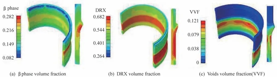
Fig.9 Prediction of microstructure and damage distributions obtained by the modified GTN model coupled with the microstructure evolution mechanism[28]

Fig.10 Evolutions of the radial damage under different processes and roller geometric parameters obtained by the modified GTN model coupled with the microstructure evolution mechanism[28]
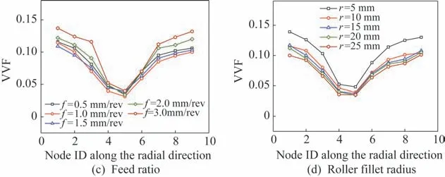
Continue Fig.10 Evolutions of the radial damage under different processes and roller geometric parameters obtained by the modified GTN model coupled with the microstructure evolution mechanism[28]

where((,)),(,P),and(,) are the void nucleation coefficient,the softening coefficient,and the critical void volume fraction related to the vol‑ume fraction of the β phase and the DRX,respective‑ly.dˉis the equivalent plastic strain increment of the matrix material.andare the void volume fraction and the critical void volume fraction,respectively.dis the plastic strain increment.is the second or‑der identity matrix. kis the undetermined parame‑ters.is the stress state function. sis the stress de‑viator.is the effective stress.is the acceleration factor related to the void growth.
WU et al.also modified the GTN model to predict the fracture defect of tubular spinning,and re‑vealed the related fracture mechanism.They found that the damage evolution was related to the wall thickness thinning rate in the multi-pass spinning of tubular parts.Under the small thinning rate(<10%),the tensile damage was in charge of the total damage accumulation.With the increase in the thinning rate,the shear damage was greater than the tensile damage,which became the main cause of frac‑ture.When the thinning rate was greater than 30%,the negative stress triaxiality on the outer layer of the tubular part inhibited the damage accumulation,so that the damage on the inner layer was greater than that of the outer layer,resulting in the fracture occurrence in the inner layer of the tubular part.
In particular,to study the multi-mode damage and fracture behavior of components with complex in‑ner ribs,we have modified the GTN model by uni‑fied tensile and shear damage through a newly pro‑posed stress state characterization equation.Then,we found that the non-rib zone was easy to fracture owing to the shear effect of the roller and the axial tension effect of the unformed zone under the large wall thickness thinning rate,while the axial tension dominated deformation led to the fracture of longitu‑dinal ribs under a large transverse rib groove interval.The high stress triaxiality and large equivalent plastic strain were responsible for the rapid accumulation of damage,but the different magnitudes of them result‑ed in the different damage evolutions of the longitudi‑nal rib and non-rib zones,indicating the diverse frac‑ture mechanisms.
It can be seen that the finite element model con‑sidering ductile fracture criteria can reveal the distri‑bution and evolution law of damage in spinning.Meanwhile,the fracture moment and location can be effectively predicted,which is of great significance for practical engineering application.According to the spinning deformation characteristics,the modified ductile fracture models expand their applicability and improve their prediction accuracy,so as to make a better prediction for the damage and fracture defects.Therefore,the establishment of a suitable ductile fracture model is the key to the development of accu‑rate spinning techniques.
3 Conclusions
In recent years,the demands and performance requirements for high-performance thin-walled com‑ponents are increasing with the rapid development of the aerospace field.Spinning,as an important tech‑nique for manufacturing high-performance compo‑nents,is playing an increasingly significant role.However,fracture is easy to occur in shear spinning of conical parts and flow spinning of tubular parts at different positions and in different forms,especially in the components with hard-to-deform materials and complex structure.The risk of fracture can be low‑ered by adjusting the processing parameters and choosing reasonable heat treatment schemes.
In view of the high cost of experimental study on spinning,finite element simulation is an effective means to study the damage and fracture behavior and obtain the optimized process parameters.To improve the prediction accuracy of finite element simulation,a large number of ductile fracture models have been proposed and continuously modified.Consequently,the ductile fracture models turn to be more and more complex,and a large number of model parameters are introduced.Therefore,how to combine the com‑plex forming characteristics and deformation modes of components to develop high-precision fracture pre‑diction models,calibrate the relevant parameters ac‑curately,and thus make the models have better appli‑cability in spinning is the major problem and chal‑lenge for the accurate prediction of damage and frac‑ture in spinning.Among them,the widely used stiff‑ened components with complex loading paths and multi-mode damage is one of the most concerned is‑sues in spinning.

- 上海航天的其它文章
- Development and Application of Ti-based Alloy Casting Technologies in the Field of Aerospace
- Applications of Magnesium Alloys in Aerospace and Aviation
- Repair Welding of Casting Magnesium Alloys:A Review
- Research on Residual Stress Measurement of Magnesium Alloy Cabin Castings
- Microstructure and Hot Deformation Behavior of Mg-9Al-3Si-0.375Sr-0.78Y Alloy
- Effect of Semi-solid Isothermal Heat Treatment on Microstructure of VW63Z Alloy