Research on Residual Stress Measurement of Magnesium Alloy Cabin Castings
YIN Lan,FANG Yu,WU Yunxin,3,ZHANG Tao,LI Chengxin,GONG Hai
(1.Light Alloy Research Institute,Central South University,Changsha 410083,Hunan,China;2.State Key Laboratory of High Performance Complex Manufacturing,Central South University,Changsha 410083,Hunan,China;3.College of Mechanical and Electrical Engineering,Central South University,Changsha 410083,Hunan,China;4.Shanghai Spaceflight Precision Machinery Institute,Shanghai 201600,China)
Abstract:Owing to the nonuniform wall thickness and complex internal structure,the measurement of the residual stress on magnesium alloy cabin castings is complex and difficult extremely,and thus seldom research has focused on the residual stress of magnesium alloy castings.In this paper,the blind-hole method,the X-ray diffraction(XRD)method,and the contour method are used to conduct comprehensive and systematic residual stress tests for a magnesium alloy cabin casting.The results show that the residual stress on the surface of the casting obtained by the blind-hole method is between -20.03 MPa and -71.03 MPa,the residual stress obtained by the XRD method is between -26.01 MPa and -87.11 MPa,while the residual stress obtained by the contour method is between -45.89 MPa and 76.87 MPa.The study can lay a basis for the subsequent research of magnesium alloy cabin castings,and provide a reference for the residual stress test of magnesium alloy castings.
Key words:magnesium alloy;residual stress;XRD method;blind-hole method;contour method
0 Introduction
Mg-10Gd-3Y-0.3Zr(GW103K)magnesium al‑loy is a rare earth magnesium alloy.It has the charac‑teristics such as high strength,good heat resistance,light weight,and good casting,and has been widely applied to the large and complex casting parts in the aerospace field.However,such phenomena as cracking,deformation,and dimensional deviation may occur in the castings,owing to the inevitable ex‑istence of residual stress.The residual stress serious‑ly affects the strength of the component materials and their related performance,and should be accurately monitored.Therefore,the accurate test of casting re‑sidual stress is of great significance for improving the utilization rate of magnesium alloy and improving the quality of aviation aircraft.
Many residual stress test methods have been de‑veloped.According to the damage degree of test pieces,the test methods can be divided into destruc‑tive testing methods and non-destructive testing methods.Commonly used destructive testing meth‑ods include the blind-hole method,the crack compli‑ance method,and the profile method,while com‑monly used non-destructive testing methods include the XRD method,the neutron diffraction method,and the ultrasonic method.LI et al.measured the welding residual stress of beam-column joints with the blind-hole method,and obtained data consistent with the simulation results.MAARTEN et al.used the crack compliance method to determine the residual stress of the bottom plate and welding speci‑mens.XIE et al.combined the profile method and the X-ray diffraction method to measure the quench‑ing residual stress of the aluminum alloy component,and accurately described the quenching residual stress field of the T-shaped component.LIU et al.used the X-ray diffraction method to measure the residual stress of the tube blank with a large deformation free compression diameter,and obtained data consistent with the theoretical analysis results.Compared with the X-ray diffraction method,the neutron diffraction method has stronger penetrating power and can be used to measure the residual stress inside a larger sol‑id material.However,the neutron diffraction stress test equipment is expensive,and the running time is long.Therefore,it is less used in China now.FIORI et al.determined the three-dimensional distribution law of residual stress for automobile steel gears with the neutron diffraction method.WANG et al.pro‑posed an improved ultrasonic method to measure the plane stress in orthotropic materials.
The research time of magnesium alloy as a structural material is relatively short,and the research on its residual stress is still in its infancy.In this paper,the blind-hole method,the X-ray diffraction method,and the profile method are used to test the residual stress of a magnesium alloy cabin casting,respectively.The obtained results can provide an experimental basis for the subsequent heat treatment and machining process for magnesium alloys and provide some reference for the residual stress testing technology.
1 Blind‑hole method
1.1 Basic principle of the blind-hole method and the strain release factor
The blind-hole method was first proposed by MATHAR in 1934,and gradually improved by SOETE and other scholars.In 1981,American Soci‑ety for Testing Materials(ASTM)included the blind-hole method in the ASTM E837-81 standard named as Standard Test Method for Residual Stress Determination by the Borehole Strain Method.The blind-hole method was also published in the national standard GB/T 31310―2014 in China.The mea‑surement principle is simple.Firstly,paste the strain gage on the surface of the workpiece.Secondly,drill a hole in the center of the strain gage to break the original residual stress field,and release the residual stress of the blind-hole accessories.Thirdly,mea‑sure the strain change.Finally,calculate the residual stress according to the relevant principles of elastici‑ty.
Before the residual stress is released,theandcoefficients are calculated according to the calibra‑tion test.A unidirectional stress field is applied to the specimen so that one direction of the strain gage is parallel to the direction of the applied stress.Make the maximum principal stressapplied to the strain gage be equal to the stressapplied by the external load,and then drill the hole.After the drilling is com‑pleted,measure the strain of the strain gage.Then,the values ofandcan be obtained by

whereandare the stress calibration constants,andare the strain values,andis the stress.In or‑der to accurately measure the residual stress under different stress levels,the calibration stresses are,re‑spectively,equal to 0.3,0.5,and 0.7,whereis the yield stress of the material.Then,andare graded,by which the errors generated by the plastic deformation of the hole edge can be avoided.
Generally speaking,the surface residual stress measured by the blind-hole method is a plane stress state,and its two-way principal stress and directional angle are unknown.Therefore,it is necessary to use three-way strain rosettes to measure the stresses.The low-speed drilling method is adopted in this arti‑cle,with which the residual stress values of the mea‑suring point can be calculated by


1.2 Experimental procedure
The material is magnesium alloy.The test in‑struments include HK21B drilling device,YE2533 program-controlled static strain gauge,multimeter,etc.The strain rosette is TJ120-1.5-1.5,type A.The measurement procedure mainly consists of at‑taching the strain gage,drilling the hole,and record‑ing the readings of the strain gauges.The drilling pro‑cedure of the measuring points is shown in Fig.1.The marking diagram of the measuring points on a workpiece is shown in Fig.2.In order to understand the residual stress distribution on the surface of a magnesium alloy cabin casting,three paths are con‑sidered,i.e.,Path L1,Path L2,and Path L3,as shown in Fig.2.

Fig.1 Picture of specimen point drilling

Fig.2 Marking diagram of the measuring points
1.3 Results and analysis
During the test,the first direction of the strain gage corresponds to the axial direction and the third direction corresponds to the circumscribed direction(see Fig.2).The residual stress test results of the blind-hole method are shown in Tab.1.As can be seen from Tab.1,the surface stress of the magne‑sium alloy cabin casting is compressive,and the val‑ue is between 20.03 MPa and 71.03 MPa.The stress evolutions of different paths,i.e.,(a)L1,(b)L2,and(c)L3,are shown Fig.3.The analysis results of the test results shown in Fig.3 are as follows.

Fig.3 Residual stress evolutions of different paths

Tab.1 Results of the blind-hole method
1)The axial residual stress and the circum‑scribed residual stress have roughly the same varia‑tion trend,but the absolute value of the circum‑scribed residual stress is slightly larger than that of the axial residual stress.
2)The stress of Path L1 from Point 1 to Point 10 basically shows an increasing trend.This is be‑cause there are bars on the inner surface of the cabin casting at Points 4,7,and 10 and the stress gradual‑ly increases with the increase in the wall thickness.
3)The residual stress of Path L2 is basically sta‑ble.This is because there is an internal hole at Point 11 and the wall thickness is thinner,which make the residual stress value become smaller.
4)On Path L3,there is a stiffened rib plate in‑side the cabin.The residual stresses of the first two measuring points are larger than those of Paths L1 and L2.This is because the internal structure of Point 9 is complex,the cold iron is added during cast‑ing,and thus the residual stress can be controlled.
2 X‑ray diffraction method
2.1 Theory of the XRD method
Among all kinds of non-destructive residual stress testing methods,the XRD method is the most widely used one in the field of material science and mechanical engineering at present.The test principle is as follows:when there is residual stress inside a material,the material lattice spacing will change,which will results in a certain strain on the microscop‑ic scale.X-ray can emit diffraction when it penetrates a metal lattice.The XRD method measures the residual stress value by measuring the change of the material lattice spacing.Based on the sinmeth‑od,the stress σcan be expressed as follows:

whereis the angle between the normal projection of the diffracted crystal plane and a specified direction on the specimen plane,is the angle between the normal of the sample and the normal of the diffracting lattice plane,εis the strain in the direction defined byand,and(1/2)is the X-ray elasticity con‑stant of the lattice planes{}.
The lattice strain εcan be expressed by the in‑terplanar spacing as follows:

whereand drepresent the interplanar distances of the lattice planes{}of an unstrained specimen and a strained specimen,respectively.Bothand dsatisfy

whereis the wavelength of the incident X-rays,andand θrepresent the Bragg angles of the lattice planes{}of an unstrained specimen and a strained specimen,respectively.
2.2 Experimental procedure
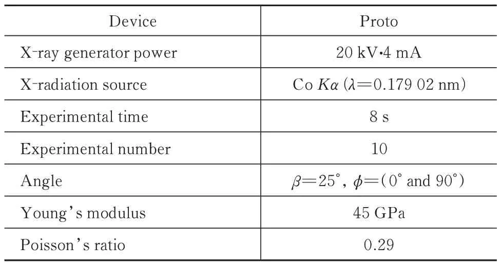
When the residual stress of a magnesium alloy sample is determined by the XRD method,it is diffi‑cult to test the magnesium alloy sample because the XRD signal of the magnesium alloy material is not strong enough.However,as a nondestructive testing method of residual stress,the XRD method has an important reference function to judge the residual stress.Therefore,residual stress XRD tests are car‑ried out on magnesium alloy samples to explore the best diffraction parameters.To obtain the residual stress on the surface of the cabin casting,using the Proto device that is convenience and efficiency.Ex‑perimental results show that X-radiation source using Co targets can acquire great results,and the detailed parameter settings of the X-ray diffractometer are shown in Tab.2.

Tab.2 X-ray measurement parameters for the residual stress tests with the XRD method
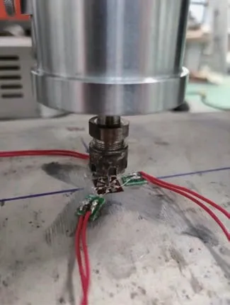
Test points and Path L4 are shown in Fig.4,which are selected from the measurement point acces‑sories of the blind-hole method.The surface is treat‑ed with electrolytic polishing.In the stress test with the X-ray diffraction method,the axial and circumfer‑ential directions are consistent with those of the blindhole method.The test process is shown in Fig.5.

Fig.4 Test points and Path L4

Fig.5 Measurement setup with Proto
2.3 Results and analysis
When the XRD method is used to test the resid‑ual stress of the magnesium alloy cabin casting,4 points are selected along the axial direction to form Path L4.The test results are shown in Tab.3.It can be seen from Tab.3 that the surface stress of the workpiece is compressive and the residual stress val‑ue is between 26 MPa and 88 MPa.

Tab.3 Results of the X-ray diffraction method
The residual stress evolutions of Path L4 are shown in Fig.6.It can be seen from Fig.6 that the axial stress is slightly smaller than the circumferential stress,and the value of the stress shows an increase trend as the axial distance increases.In particular,the residual stress of Point ③increases because it is at the connection between the upper plate and the shell,while the residual stress of Point ④is the larg‑est since Point ④is at the connection between the side wall of the rudder shaft hole and the shell where the wall thickness is the thickest.

Fig.6 Residual stress evolutions of Path L4
Comparing the test results of the XRD method and the blind-hole method,one can see that the stress value obtained by the XRD method is slightly larger than the stress value obtained by the blind-hole method.The detection depth of the XRD method is on the order of 10 microns,while the detection depth of the blind-hole method is on the order of millime‑ters.There is a gradient in the stress field,and there will be some differences in the detection results of the two methods.Besides,the detection error of the XRD method instrument is about 10 MPa,while the systematic error of the blind-hole method involves many factors and is generally more than 10 MPa.Therefore,the surface residual stresses measured by the blind-hole method and the XRD method are equivalent to each other,which can basically confirm each other.
3 Contour method
3.1 Theory of the contour method
In this paper,the contour method is used to test the residual stress cloud diagram of the circumferential section of the magnesium alloy cabin casting.The contour method was proposed by Prime in 2001.It mainly combines the finite element meth‑od and the stress relief technology to test the internal stress of a component.The test principle is derived from the Bueckner superposition principle.Firstly,cut the test piece along a certain plane.Secondly,de‑form the cutting surface profile generated by the stress release.The deformation profile is assumed to be caused by the elastic release of the residual stress.Thirdly,measure the deformation profile of the cut‑ting surface accurately,and process the measured profile data.Finally,use the fitting results as the ba‑sic data of the finite element model,and obtain the stress distribution inside the component perpendicu‑lar to the cutting plane through elastic calculation.
3.2 Experimental procedure
Firstly,the workpiece is divided into two halves by Suzhou Sanguang DK7625P slow-moving wire cutting machine.The average wire speed is set as 1 mm·min,and the cutting wire is a copper wire with0.25 mm.In order to ensure the hypothetical conditions of plane cutting,the two sides of the cut‑ting surface are clamped symmetrically in the experi‑ment.Secondly,the obtained cutting plane is mea‑sured by using the three-coordinate measuring ma‑chine.The distance between the measuring points is 3 mm×3 mm,and the error is 0.1 μm.The cutting surface of the workpiece is shown in Fig.7.

Fig.7 Cutting surface of the workpiece
When a three-coordinate instrument is used to measure the contour,since the test piece cannot main‑tain the absolute level,the result of the measurement contour will be superimposed on the original inclined surface.Contour envelope processing can eliminate this error.In addition,the contour will be deformed at the sudden change of the cutting current,and smooth contour fitting can reduce this error.Contour fitting can also eliminate some measurement errors.
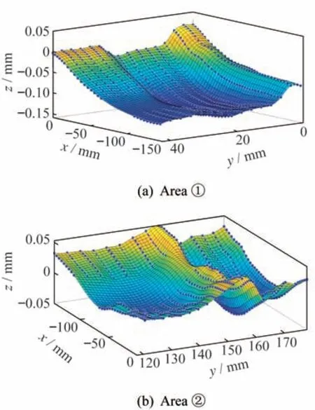
In this paper,the final contour data interpolated on the node coordinates are obtained by Matlab soft‑ware,and the Gaussian mixture model is used for the fitting.Areas ①and ②are divided into 5×5 grids.The final contour data are shown in Fig.8.It can be seen from Fig.8 that the contour of Area ①is rela‑tively smooth,while there is a higher peak value on the contour of Area ②.The existence of the peak val‑ue in Fig.8(b)is because of the short circuit and wire breakage during the slow wire cutting process.

Fig.8 Contour data
3.3 Results and analysis
The specimen model is established in ABAQUS,and the above processed contour data are inverted as the displacement boundary condition and loaded into the model.The Poisson’s ratio is 0.29,and the elastic modulus is 45 GPa.The mesh ele‑ment is determined to be a hexahedral eight-node one.The normal stress cloud diagram of the crosssection is shown in Fig.9.It can be seen from Fig.9 that the maximum tensile stress exists in the core of the thicker part of the cross-section.Besides,com‑pressive stress exists in the outside part of the crosssection(boundary),while tensile stress exists in the inside part of the cross-section.In order to further study the distribution of the residual stress,four paths are taken in Area ①and Area ②,respective‑ly,as shown in Fig.10.

Fig.9 Normal stress cloud of the cross-section

Fig.10 Path diagram
The stress distributions of Areas ①and ②are shown in Fig.11.Excluding the error of the contour method boundary,the stress in Area ①is roughly internally tensioned and externally compressed.It presents a bimodal stress distribution similar to that of a thick plate.Moreover,the maximum tensile stress is 76.87 MPa,and the maximum compressive stress is 45.89 MPa.

Fig.11 Stress distributions of different paths in Areas ①and ②
In addition,the radial wall thickness of the two paths on the left is thicker than that on the right.During the cooling process,the temperature differ‑ence between the surface and the core generates larg‑er residual stress,which makes the residual stress value of the left path slightly larger than that of the right one.In Area ②,the stress distribution pres‑ents a bimodal shape,the maximum tensile stress is 53.21 MPa,and the maximum compressive stress is 23.18 MPa.
4 Conclusions
In this paper,the residual stress in a magnesium alloy cabin casting is detected with the blind-hole method,the X-ray diffraction method,and the con‑tour method,respectively.The residual stresses on the surface,near surface,and internal cross-section of the magnesium alloy cabin casting are detected.The specific conclusions are as follows:
1)The test results with the blind-hole method show that the surface stress of the magnesium alloy cabin casting is compressive,and its value is be‑tween 20.03 MPa and 71.03 MPa.The stress will be relatively larger when the wall thickness increases.Moreover,there is a certain stress concentration at the connection between the rudder shaft orifice plate and the shell.
2)The test results of the X-ray diffraction meth‑od show that the residual stress on the outer surface of the magnesium alloy cabin casting is compressive,and its value ranges from 26.01 MPa to 87.11 MPa.The test results are comparable to those of the blindhole method,and can be mutually verified.
3)It can be known from the test results of the contour method that there is a certain regularity in the internal residual stress of the magnesium alloy cabin casting.The results present a bimodal stress distribu‑tion similar to that of the thick plate.The stress is be‑tween -45.89 MPa and 76.87 MPa.
- 上海航天的其它文章
- Development and Application of Ti-based Alloy Casting Technologies in the Field of Aerospace
- Applications of Magnesium Alloys in Aerospace and Aviation
- Repair Welding of Casting Magnesium Alloys:A Review
- Microstructure and Hot Deformation Behavior of Mg-9Al-3Si-0.375Sr-0.78Y Alloy
- Effect of Semi-solid Isothermal Heat Treatment on Microstructure of VW63Z Alloy
- Study on the Deformation Behavior of Mg-Gd-Y-Zn-Mn Wrought Magnesium Alloys by Visco-plastic Self-consistent Modeling

