
Wheeled jumping robot by power modulation using twisted string lever mechanism∗
2021-11-01 09:08XianweiLIUYongbinJINLeiJIANGHongtaoWANG
Xian-wei LIU,Yong-bin JIN,Lei JIANG,Hong-tao WANG,4
1State Key Laboratory of Fluid Power and Mechatronic Systems,Zhejiang University,Hangzhou 310027,China
2Center for X-Mechanics,Zhejiang University,Hangzhou 310027,China
3Institute of Applied Mechanics,Zhejiang University,Hangzhou 310027,China
4Zhejiang Lab,Hangzhou 311121,China
Abstract:This study introduces a wheeled robot platform with jumping ability.To realize jump movement,a twisted string lever mechanism is used,which is characterized by its compactness and variable gear ratio.Based on robot modeling and parameter calculation,the twisted string actuator shows its advantage when applied to situations such as jumping of robots,where explosiveness of output force matters.In this study,a wheeled bipedal robot equipped with the twisted string actuator is designed and fabricated.It weighs 16.0 kg and can perform jumps when it encounters obstacles.The prototype can jump up to a stage with a maximum height of 1.0 m using electric power,which is approximately 1.5 times the height of its stretched legs.
Key words:Wheeled jumping robot;Twisted string lever mechanism;Non-linear transmission ratio
1 Introduction
Mobile robots with locomotion ability on the ground are generally categorized into wheeled robots and legged robots according to the specific types of motion(Hutter et al.,2016;Bledt et al.,2018).The motion of wheeled robots is smooth and continuous on flat grounds,leading to the overwhelming advantage of fast traveling speed and high efficiency when actuated by electric motors.However,an obstacle of a similar size to the wheels can easily obstruct the movement of wheeled robots,exposing relatively poor terrain adaptability.This motivates the research on legged robots,which can step or even jump over obstacles of a similar size or even sizes larger than themselves.Meanwhile,their mobility and motor efficiency will be greatly decreased for hybrid motion,i.e.alternative discrete foot contact and continuous leg swinging.A wheel-legged robot is a promising scheme to trade offthe mobility and terrain adaptability of legged and wheeled robots,respectively.The most famous Handle robot from Boston Dynamics Company,USA has demonstrated impressive maneuverability,which can travel at a speed of 4 m/s while maintaining excellent dynamic stability.It can also jump to a desk top using a leg mechanism driven by a compact mobile hydraulic system.Wheeled-legged robots have attracted more attention for the combined rough-terrain capability of legs and the efficiency of wheels.By considering weight,complexity,and costs,more wheel-legged robots are designed using electric motors,instead of hydraulic actuators.Both the ANYmal robot(Bjelonic et al.,2020)and the Ascento robot(Klemm et al.,2019)from ETH Zurich,Switzerland are representatives of such systems.The disadvantage is the relatively poor performance in jumping ability,which requires excessive power density for on-shelf electric motors.
In general,three different schemes are used in motor-driven jumping robots(Fig.1).A rigid gear transmission between legs and motors,as schematically shown in Fig.1a,is the most commonly adopted mechanism for simple architecture.A representative is the Cheetah III robot from Massachusetts Institute of Technology(MIT),USA(Bledt et al.,2018)using specially designed motors,coupled to a low gear ratio transmission to achieve high torque density,high back drivability,and high bandwidth force control through proprioception(Wensing et al.,2017).A jumping height of approximately 0.7 m has been reached by the Cheetah III robot weighing 40 kg.Energy storage elements are commonly used to minimize the power density requirement so that energy can be stored in advance and released right at the time for jumping.The power level can be higher than what the motors themselves can produce.Energy storage elements can be either series-elastic(SE)or parallel-elastic(PE)units(Figs.1b and 1c).A PE robot has an elastic element attached in parallel to the leg structure,coupling leg extension to energetic state(Yesilevskiy et al.,2015).Its energy storage is limited only by the maximum actuator force and the strain-energy storage density of the elastic units.In comparison,an SE robot installs the elastic unit by connecting the motor and the leg structure so that the leg stance is decoupled from the energy state(Paluska and Herr,2006).By incorporating such a compliant element,it also enables power modulation and passive energy recovery(Haldane et al.,2016).Combining the SE scheme and the power modulation technique,the Salto-1P robot from University of California at Berkeley,USA has demonstrated a maximum jumping height of approximately 1.2 m,which has a mass of 0.15 kg and a leg extension of 0.15 m(Haldane et al.,2017).
Fig.2 summarized the various jumping robots and animals by correlating the jumping height and the body mass in kilogram.It is interesting to observe that the upper limit of the jumping height is bounded by a banana-shape curve despite the driven schemes and the number of legs.This implies a trade-offbetween the jumping ability and weight,i.e.smaller robots usually jump higher.The 80-kg Handle robot and the 40-kg Cheetah III robot break this dilemma,which have achieved jumping heights of 1.2 m and 0.7 m,respectively.However,both robots are famous for their design,especially the high-power density actuators(Wensing et al.,2017).
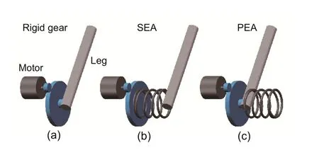
Fig.1 Three different schemes for motor-driven jumping robots:(a)rigid gear transmission;(b)series-elastic actuator(SEA);(c)parallel-elastic actuator(PEA)
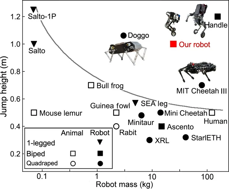
Fig.2 Comparison for legged jumping robots and animals.The vertical axis is the maximum jumping height observed for each robot platform.The horizontal axis is the mass in logarithmic coordinate system.Animal species:bull frog(Astley et al.,2013)and guinea fowl(Henry et al.,2005).Robot species:XRHex Lite(XRL)(Johnson and Koditschek,2013),SEA leg(Gualillo et al.,2008),Minitaur(Kenneally et al.,2016),Mini Cheetah(Katz et al.,2019),and Doggo(Kau et al.,2019)
In this study,we propose a novel scheme by simply replacing the rigid gear with a flexible twisted string in realizing a variable transmission ratio,which modulates the electric motor power output in the takeoffphase during jumping.A wheel-legged robot,named as Wu Kong robot,has been built using commercially available electric motors and the twisted string lever mechanism(TSLM).It has a mass of 16 kg while retaining its high jumping ability.The maximum achieved jumping height is 1.0 m,which is well above the banana curve in Fig.2.
2 System design
2.1 System overview
We introduce the medium-sized Wu Kong wheel-legged robot,as shown in Fig.3.It comprises two legs and four motors.Each leg is made of one four-bar linkage.The wheel is installed at the end of the calf bar of the linkage and driven by an electric motor.The side length of the trapezoid defined by the four joints is optimized so that the mass center is located on the straight line between the wheel center and the hip joint during leg extension.The trace of the mass center is indicated by the green line in Fig.3c.In this way,the jumping action does not lead to body rotation if the robot is in its upright position.Such design simplifies the dynamic system model as the classical cart-pole system(Fig.3d)with pole length varying from 22 cm in the rest position(Fig.3a)to 60 cm in the stance position(Fig.3b).The leg extension is actuated by a twisted string(Würtz et al.,2010)that connects the motor and pin joint and the leg contraction is realized using a spring installed on each leg,as shown in Figs.3a and 3b.Notably,the motor is hinged to the extension part of the thigh bar with its rotation axis being vertical to that of the hip joint.In this way,the rotation axis direction of the motor will be aligned to the twisted string adaptatively.The triangle,highlighted in both Figs.3a and 3b,is,thus,formed by frame linkage,the extension part of the thigh bar,and twisted strings.Upon the motor rotation,an axial force can be generated by the twisted strings,which actuates the hip joint through the torque induced by the lever mechanism.The twisted string coupled at a lever mechanism transforms the linear motion to the rotation of the joint.For simplicity,this mechanism is called TSLM throughout the text.
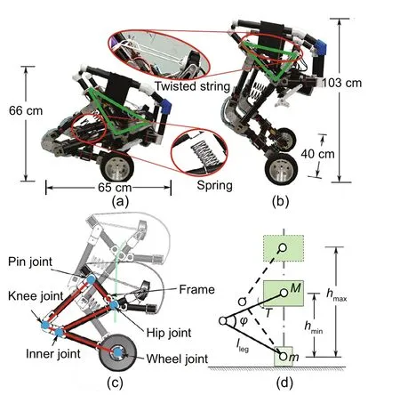
Fig.3 Overview of the system design:(a)robot in the rest position;(b)robot in the stance position;(c)leg design comprising a four-bar linkage,as highlighted in red,installed with the TSLM and an electric motordriven wheel;(d)simplified cart-pole model for Wu Kong robot.The height h is defined as the distance between the body mass center and the wheel center,which reaches the minimum(hmin)and maximum(hmax)in the rest and stance positions,respectively.The length of leg(lleg)and the knee joint angleϕ are indicated.M is the body mass,m is the mass of wheels,and T is the torque.References to color refer to the online version of this figure
The developed prototype is a biped wheel-legged robot composed of a linkage,two rotational twisted string actuators,two optimized 1-DOF(degree of freedom)legs,and two wheels.All parameters are listed in Table 1.The hardware components have been chosen to best meet the system’s performance requirements.High speed is necessary in the hip motor for jumping ability.For this purpose,commercially available DJI M12 motors are used,which have a peak speed of 6000 r/min with a voltage of 48 V.An external magnetic encoder is installed for accurate position and velocity feedback.Homemade modular brushless direct-current(DC)motors are used for driving the wheels,which have a built-in angular sensor and a gear set with a reduction ratio of 6.The maximum torque output is 18 N·m,and the designed rotation speed is 300 r/min,guaranteeing a traveling speed of approximately 4.0 m/s.The communication among all four motors follows the controller area network policy.The robot is equipped with an onboard microcontroller unit(MCU)Nucleo-144STM32 developing board and an inertial measurement unit(IMU)WT931 for feedback control.To minimize the total mass,and increase the strength and stiff-ness so that the robot can jump higher and achieve a better control performance,a carbon fiber tube was used as the major construction material of its legs.To extend the lifetime of the twisted string,we used the Dyneema cable manufactured by AiShang,a fishing line manufacturing company in China.The Dyneema cable is solid with a part number of 8 and a maximum tension of 450 N.It also has a smooth surface to prevent abrasion.The system is powered by a battery pack composed of 12-cell 48 V lithium-ion polymer batteries.The total weight of all components is 16.0 kg,with an operation time of approximately 3 h when traveling with a speed of 3.5 km/h on flat ground.
Parameter Value Mass of body,M(kg) 13 Mass of wheels,m(kg) 2 Mass of legs,mlegs(kg) 1 Length of leg,lleg(m) 0.34 Length of lever,llever(m) 0.18 Length of frame bar,lframe(m) 0.31 Minimum body height,hmin(m) 0.22 Maximum body height,hmax(m) 0.60
2.2 Twisted string lever mechanism
Fig.4 shows the schematic setup of the twisted string mechanism.Upon the motor rotation,the strands are twisted and contracted,converting the high-speed rotation into linear motion.Eq.(1)gives relation between the twisted string lengthLsand the twist angleθ:
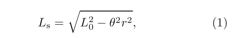
whereL0denotes the origin length of the twist string,andrdenotes the radius of the strand.Ignoring friction,the contraction forceFccan be derived from Eq.(2)by the law of energy conservation:
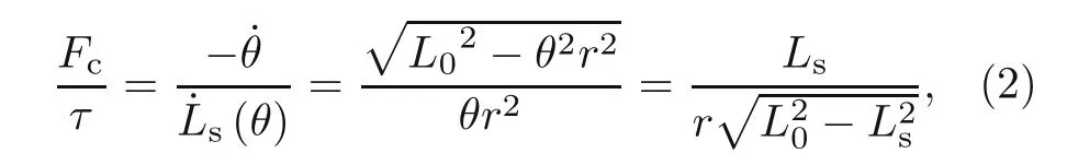
whereτis the motor’s output torque.The body heighthis defined as the distance between the body mass center and wheel center,as indicated in Fig.3d.It reaches the minimum(hmin=0.22 m)and maximum(hmax=0.60 m)in the rest and stance positions,respectively.The twisted string lengthLsand body heighthare geometrically related to the TSLM triangle indicated in Fig.4b:
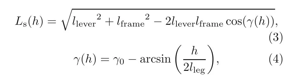
wherellever,lframe,andγ(h)are the lengths of the two edges and the included angle,respectively,andγ0=134◦is the angle between the body frame and horizontal line.Therefore,the torque applied to the hip joint can be calculated as follows:
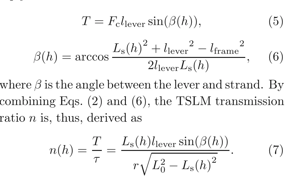
The above equation reveals that the transmission ratio is a nonlinear function of the heighth.Other parameters,such as string radius and lever length,can be used to adjust the geometrydependent transmission ratio to modulate the motor power output for jumping applications.Fig.5 plots the TSLM transmission ratio as a function of the body height and string radius.Wu Kong robot uses a string of 8 mm in diameter and 35 cm in length.
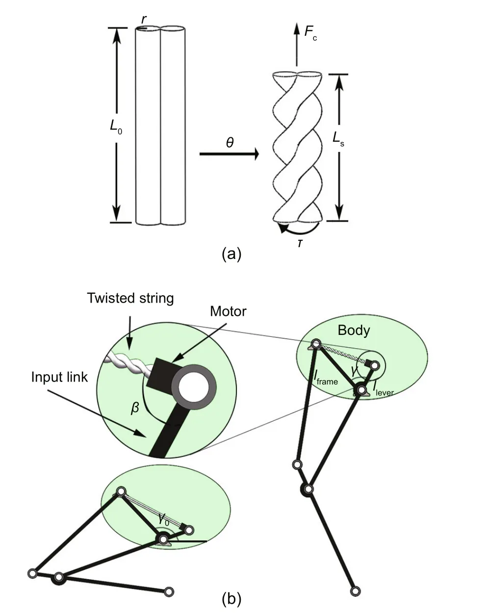
Fig.4 A schematic of the twisted string mechanism(the string length is reduced from L0 to Ls after twisted for an angleθ)(a)and the schematic of the leg installed with the TSLM in the rest(left)and stance(right)positions(b).The inset shows the setup of the TSLM.The geometry parameters(lframe and llever)are indicated in the leg schematic in the stance position.Their specific magnitudes for Wu Kong robot are listed in Table 1
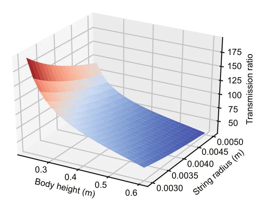
Fig.5 Nonlinear transmission ratio of the TSLM
To characterize the energy efficiency of the twisted string mechanism,we performed a work loop test using it.Fig.6a shows the experimental platform,which is set up by an aluminum profile.We use the same type of motor,motor actuator,and Dyneema string on the robot.The motor is actuated to spin at a constant speed to lift a load of 9 kg with the twisted string.The height and speed of the load rising can be obtained using a laser distance sensor;thus,the input power and output power of the twisted string can be calculated.During the experimental process,the length of the string changes from 80 to 40 cm,and the input power,output power,as well as efficiency of the twisted string,are plotted in Fig.6b.Overall,the efficiency is greater than 75%and tends to decrease rapidly after the lifting height reaches the threshold.This may be caused by high order twisting of the string,which should be avoided in mechanical design.
2.3 Controller design
Fig.3d shows the simplified dynamics model of Wu Kong robot.We note that only the body massMand the mass of two wheelsmare considered,while the mass of the legs is neglected.In Wu Kong robot,light-weight and high-strength carbon fiber tubes are used to build the leg structure.The weight of two legs is approximately 1 kg,approximately 6%of the total weight(16 kg).In the controller design,this simplification is well compensated for by the feedback control.In addition,we highlight that the body motion is restricted to a straight line connecting the center of the body mass and the center of wheels for optimized linkage geometry.The extension and contraction of legs do not change the robot’s horizontal position of the mass center.This greatly simplifies the model and decouples the control for balance and jumping.The architecture of the controller is shown in Fig.7.
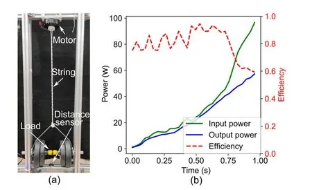
Fig.6 Experiment platform to characterize the twisted string mechanism efficiency(a)and the input power,output power,and efficiency of the twisted string during the experiment process(b)
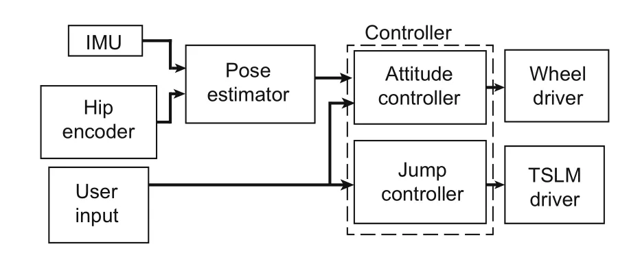
Fig.7 Overview of the controller architecture
If the body heighthis fixed,Wu Kong robot can be further simplified as a cart-pole system shown with fixed pole length(Fig.8a).The dynamics of the system can be described as
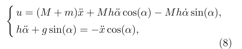
wherexrepresents the horizontal position,gis the gravity acceleration,αis the tilting angle,anduis the horizontal input force applied to the wheels.After linearization,the above equation can be cast into the following form:
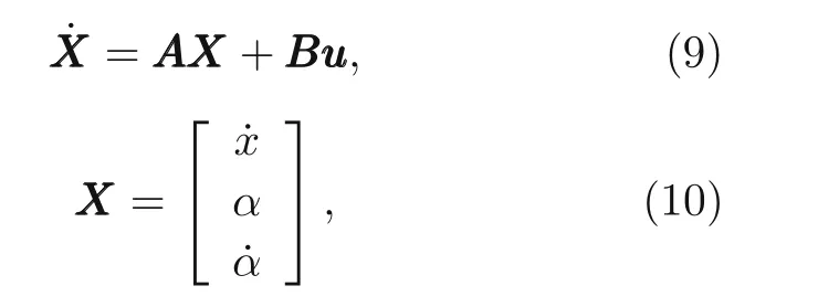
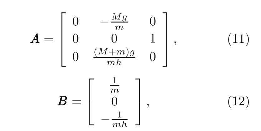
whereuuuis the horizontal input force vector.The linear quadratic regulator(LQR)is used for balance control.The infinite horizon quadratic cost function is
It also turns out that this algorithm is effective in balance control even during leg extension or contraction if theAAAandBBBmatrices are updated accordingly.Here,the robot stateXXXis estimated using the Kalman filter to combine the angle and angular velocity in the pitch direction from an inertial measurement unit sensor and the angle from the wheel motor encoder.Turning control is realized through the differential speed between the left and right wheels,as schematically shown in Fig.8b.The minimum turning radius is zero.
As soon as the robot receives a jump trigger,the motors of the TSLM on both the left and right sides of the robot,first,adjust their position to keep the two legs in the same posture.Then,a preset torque command is given to the TSLM motors.The robot body is accelerated during the leg extension.To realize a higher jumping height,the legs are retracted in air,driven by two springs installed in the lower thigh bar,as shown in Fig.3a.Notably,one end of the spring is free when the robot is in the rest position.A small gap is left between the free end and upper thigh bar.During the leg extension,the springs begin to be compressed after the gap is narrowed to zero.Once the wheel feet leave the floor,the motor rotation is reversed and the twisted strands are relaxed.The compressed spring will release,which retracts both legs.The simple passive mechanism will fully realize leg retraction.
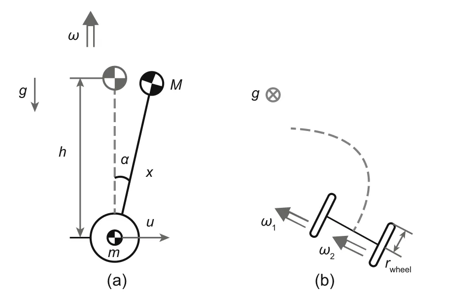
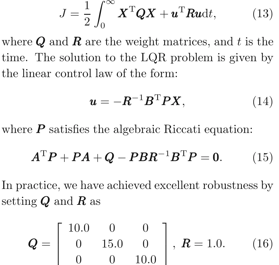
Fig.8 Model for control of the attitude,defined by the tilting angleα(ωis the angular velocity of the robot steering)(a)and the model for turning control by the differential speedsω1 andω2 of two wheels(b)
The final jumping height is determined by the attained kinetic energy during the extension process,which is calculated by the conservation of energy:
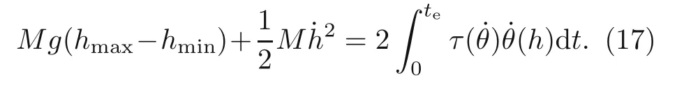
The timeteis the duration before the wheels leave the floor.Notably,τ(˙θ)is limited by the external characteristic of the motors and may not be equal to the preset torque.Following the definition of the reduction ratio,the motor speed can be represented as follows:
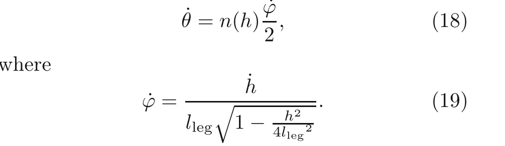
By substituting the above equations into Eq.(17),we can see that the jumping height is uniquely determined by the torque history.The external characteristic of the DJI M12 motor is given in Eq.(20)and plotted in Fig.9.
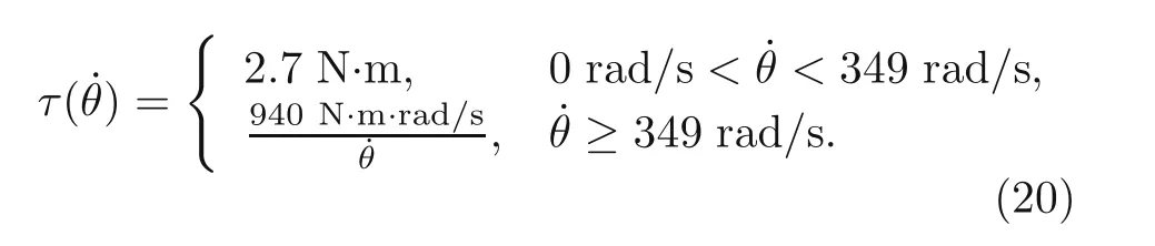
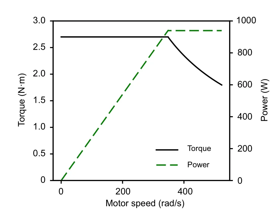
Fig.9 External characteristic curve and the output power of the DJI M12 motor
The decoupled controller has been tested in both simulations and experiments,as shown in Fig.10.The results are consistent with each other.A minimum torque is required for the robot to jumping offthe floor,which is also reflected in Eq.(17).Above this threshold,the height monotonically depends on the preset torque.In this way,the jumping height can be well controlled.
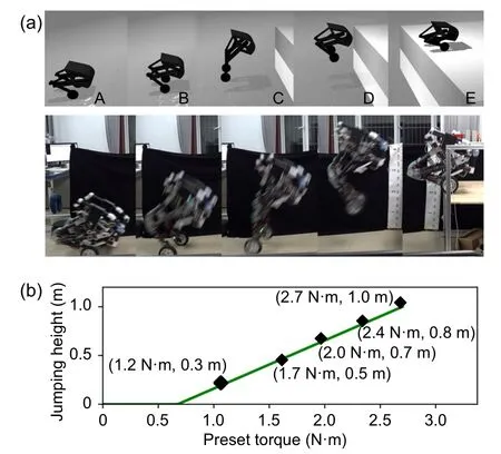
Fig.10 Jumping processes of the robot by simulations(Todorov et al.,2012)and experiments(a)and the relation between the jumping height and preset torque(b)
3 Results
Fig.11 shows a standing-up process of the robot.To verify the effectiveness of the LQR controller and TSLM,the robot receives a command to rise from a rest position to a stance position gradually.Effective controller design ensures that the robot can maintain balance at all heights.
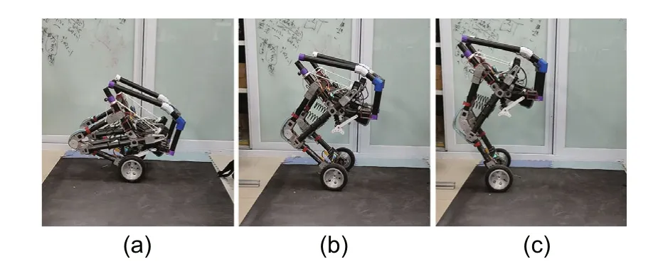
Fig.11 Standing-up process of Wu Kong robot.The robot rises from h=0.22 m to 0.60 m gradually:(a)h=0.22 m;(b)h=0.45 m;(c)h=0.60 m
Fig.12 shows the stability performance of the LQR controller.A sudden push is applied to Wu Kong robot(labeled as A state in Fig.12a),leading to a maximum tilting angle deviation of approximately 12◦.It recovered to an upright position in approximately 2 s after moving forward for 0.85 m(B state in Fig.12a).The variations of the tilting angle and torque are shown in Figs.12b and 12c,respectively.The recorded torque history reveals that the maximum applied torque by the wheel motors is less than 6 N·m.
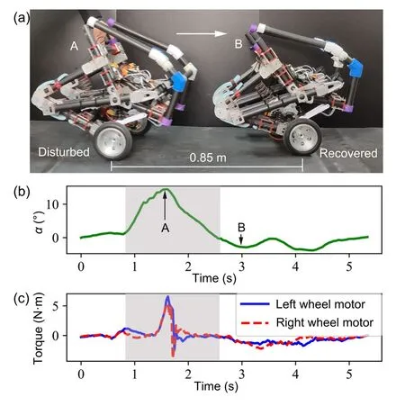
Fig.12 Balance control performance of the robot:(a)photos capturing the states of the Wu Kong robot being pushed(A)and recovered(B);(b)tilting angle variation with time after it is pushed;(c)torque output history of the wheel motors
A jump experiment at different heights is also performed to verify the feasibility of the jump controller.Fig.13 shows a small jump experiment of Wu Kong robot,where the robot is given a preset torque command of 1.5 N·m.The image shows that the jumping height is approximately 40 cm and the horizontal movement is approximately 1.3 m due to a forward speed when jumping.
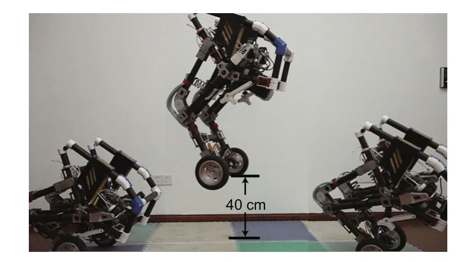
Fig.13 A small jump experiment of the robot.The jumping height is approximately 40 cm
We further test the maximum jumping ability of Wu Kong robot.As shown in Fig.14a,the robot can jump up to a 1 m-height platform.The flight time is 0.2 s,and the leg extension time is 0.28 s.Fig.14b plots the torque history during the jumping process.The maximum torque is 2.5 N·m,which reaches the limits defined by the external characteristic of the TSLM motors(Fig.9).As shown in Fig.2,the jumping height records and the natural logarithm of the body mass(in kg)are correlated with various jumping robots and animals.The upper limit of the jumping height is bounded by a banana-shape curve despite the driven schemes and the number of legs.Notably,Wu Kong robot is well above this banana curve.
4 Discussion and conclusions
For a legged jumping robot with a simplified model similar to that in Fig.3d,the mechanical advantage changes during the leg’s extension process.The electric motor used is limited by the external characteristic curve of the motor similar to that in Fig.9;thus,the use of a variable reduction ratio transmission mechanism when actuating the legs may realize a greater jumping height.
From Eq.(17),the jumping height is determined by the kinetic energy of the robot.For a legged robot whose leg configuration is similar to that of Wu Kong robot,given the preset torque and the external characteristic of the TSLM motor,the jumping height is a function of the transmission ration(h).The optimizedn(h)is given by
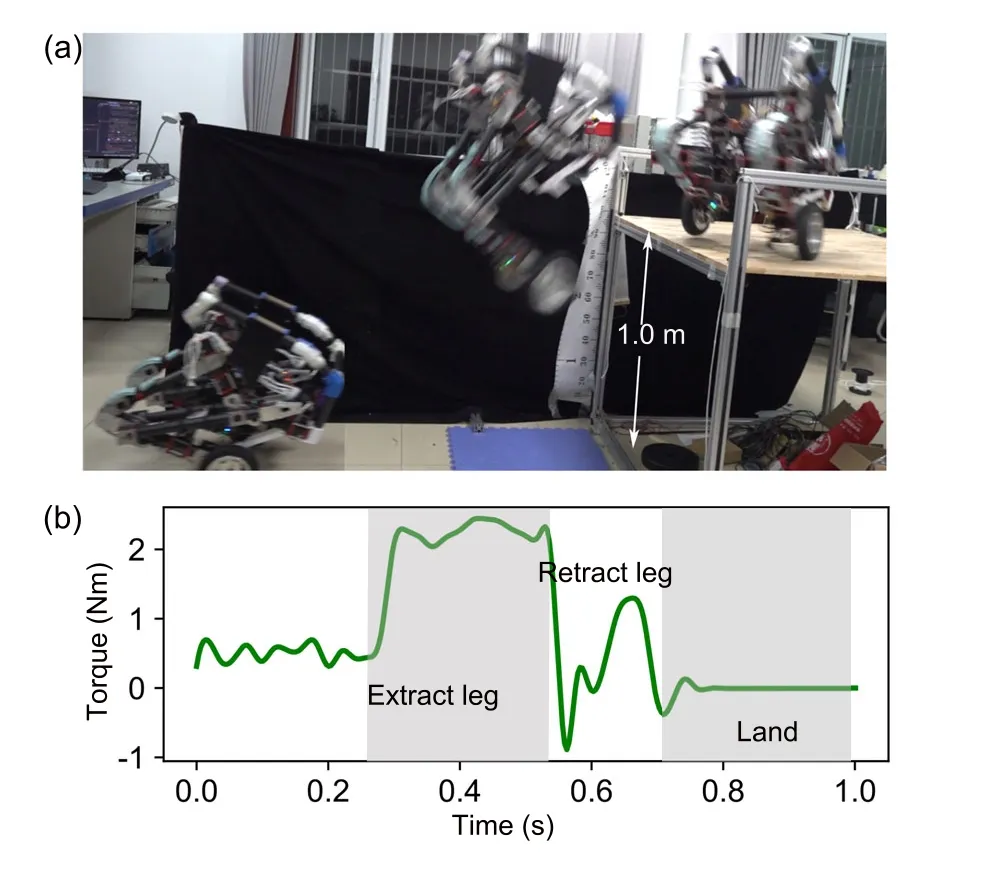
Fig.14 Image of the sequence of maximum-height jumping(a)and the graph of torque applied to a TSLM motor during the jumping process(b)
Without loss of generality,the transmission ratio is assumed to be anith-order polynomial in the following form:
The optimized nonlinear form is fully determined by the coefficientW=[w0,w1,...,wi].To achieve the maximum jumping height,we set the motor peak torque of 2.7 N·m as the input.A rigid gear transmission corresponds to a constant transmission ration,i.e.i=0.For the optimized ration=60,a maximum jumping height of 0.7 m can be achieved,which is much lower than the record set by Wu Kong robot(Fig.15a).This implies that the power of the electric motors is not effectively explored.
The jumping height of robots,such as Wu Kong robot,can be greatly improved by allowing a polynomial form with a higher order.By taking a 3rdorder polynomial form of the transmission ratio,the jumping height is increased to approximately 1 m(Fig.15a).The jumping performance is no longer improved by simply increasing the order of the polynomial.In comparison,Wu Kong robot can achieve a jumping height of 0.95 m by solving Eq.(17)using the transmission ratio in Eq.(7).Fig.15b plots the transmission ratio curves of the optimized rigid gear,
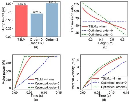
Fig.15 The maximum jumping height achieved using the transmission ratio of the TSLM and optimized zero-and 3rd-order polynomials(a),the corresponding transmission ratio curves(b),the corresponding power output history of the electric motors(the preset torque is 2.7 N·m,and the external characteristic is given in Fig.9)(c),and the corresponding velocity history before taking offthe ground(d)
the optimized nonlinear form,and the TLSM of Wu Kong robot.Notably,both the optimized transmission ratio and that of the TSLM decrease monotonically during leg extension before the wheels jump offthe floor.To achieve the maximum jumping height,a large transmission ratio is required at the beginning of the jumping process.Both ratios are similar.Moreover,the jumping height is determined by the kinetic energy of the robot,which requires the motors to attain the maximum output power as fast as possible.Fig.15c plots the motor power output versus time during the jumping process.The maximum power is attained by the motor with the optimized transmission ratio.The TSLM motor reaches the maximum power output slightly slower.Wu Kong robot reaches a velocity of 4.37 m/s,which is close to the velocity of the optimized 3rd-order polynomial reduction ratio(approximately 4.5 m/s),and the platform using the optimized constant ratio reducer only obtains a velocity of 3.6 m/s(Fig.15d).The result shows that TSLM can make full use of the motor’s capacity by modulating the power output of the electric motors and achieve a much higher jumping height than that by a rigid gear reducer when applied to legged robots with a similar structure to Wu Kong robot.
In summary,we have introduced the leg-wheeled Wu Kong robot based on the novel TSLM.Combining TSLM and the optimized design of the four-barlinkage leg has achieved both fast traveling speed and excellent jumping ability.Compared with other actuator systems,the TSLM has the advantages of high integration,lightweight,and high explosive power,making the twisted string actuator particularly suitable for use in jumping robot legs.
Contributors
Xian-wei LIU designed the research.Xian-wei LIU and Yong-bin JIN processed the corresponding data.Xian-wei LIU wrote the first draft of the manuscript.Hong-tao WANG and Lei JIANG helped to organize the manuscript.Hong-tao WANG revised and edited the final version.
Conflict of interest
Xian-wei LIU,Yong-bin JIN,Lei JIANG,and Hong-tao WANG declare that they have no conflict of interest.
 Journal of Zhejiang University-Science A(Applied Physics & Engineering)2021年10期
- Journal of Zhejiang University-Science A(Applied Physics & Engineering)的其它文章
- A comparative study of methods for remediation of diesel-contaminated soil*
- A graphics processing unit-based robust numerical model for solute transport driven by torrential flow condition*
- A novel time-span input neural network for accurate municipal solid waste incineration boiler steam temperature prediction*
- Adsorption of tetrodotoxin by flexible shape-memory polymers synthesized from silica-stabilized Pickering high internal phase emulsion*#