An improved procedure for manufacture of 3D tubes with springback concerned in flexible bending process
Jianjun WU ,Zengkun ZHANG
a School of Mechanical Engineering,Northwestern Polytechnical University,Xi’an 710072,China
b School of Intelligent Manufacturing,Nanyang Institute of Technology,Nanyang 473500,China
KEYWORDS Bending and twisting;3D tube;Finite element modelling;Materials forming;Springback compensation;Tube bending
Abstract Three dimensional (3D) tubes,which possess the characteristics of space saving,lightweight and high strength,are widely used in many high-end industries such as aviation,aerospace,automobile and shipbuilding.However,when manufacturing a 3D tube in flexible bending process,springback is a big obstacle for improving the forming quality.In this paper,a new comprehensive strategy for springback control of 3D tubes is proposed.The strategy can be described as follows:(1) define the desired shape and manufacture shape;(2) optimize the manufacture shape using two tooling design methods (e.g.DA (displacement adjustment) method and B&T (bending and twisting)method presented in this paper);(3)make a discretization of the manufacture shape to acquire the optimized forming parameters.Additionally,experiment is implemented to validate the effectiveness of the new strategy.Results show that forming parameters acquired by the new strategy are partially effective.The new strategy also demonstrates that,during 3D tubes forming,the deviation caused by over-bent elements can be counteracted by the deficient-bent elements.This principle is helpful to reduce the difficulty of parameter determination in future.
1.Introduction
Metallic tubular parts possess the characteristics such as lightweight,space saving and high strength.They can improve the performance and quality of the products and minimize the installation space required without sacrificing component strength.These special advantages lead to an increasing demand on tubular parts manufacture in recent years.1–2Presently,most tubular parts are manufactured by plastic forming process,in which springback has a great influence on the final product.When the tools are released,springback will occur due to the extrados elongation and intrados compression deformation.It is inevitable and can lead to quality problems and assembly difficulties.To get a precise shape,springback should be well controlled.
In current literatures,springback errors are mainly corrected by adjusting the tooling shape and/or optimizing the forming process.3–4The former strategy3–10is aimed at compensating the tooling shape geometrically.The latter strategy11–14is usually implemented in flexible bending process and is focused on the optimization of forming parameters.
For 2D tube with constant curvature,push bending process and rotary draw bending process (shown as Fig.1,ω refers to the rotation speed of bending die.vrefers to the feeding speed of pressure die.) are widely used.In these processes,when the tools are removed,springback can be described as the decrease of bending angle and the increase of bending radius.So,the springback compensation strategy15–20for such kind of tubes are mainly focusing on the prediction and optimization of bending angle and bending radius.

Fig.1 Principle of rotary draw bending process.
For 2D/3D tube with varied curvatures,investigations mainly focus to the improvement of bending machines presently and only a few researchers paid attention to the springback control methods.Goto et al.21,22proposed a versatile bending machine(shown as Fig.2),in which a 6-DOF Parallel Kinematics Mechanism(PKM)with a hydraulic servo drive is used to control the movements of the active die.This flexible bending machine can be applied to manufacture many kinds of 3D tubular products.But Goto didn’t introduce the strategy to control springback.Hagenah et al.23Strano et al.24and Vatter and Plettke25studied the three-roll-push-bending technology (shown as Fig.3),where a setting roll is used to control the bending plane and bending radius by either rotating around the center of the bending roll or translate in radial direction.FEM models are established to predict the forming parameters and investigate the influence of loads on the springback shape.Gantner et al.26proposed the free-bending technology (shown as Fig.4).The tube is pushed into an active bending die through the guide unit,and the bending die is joined with the guide with a spherical bearing.Gantner et al also proposed a FEM model to investigate the relation of the springback behavior and forming parameters.However,the FEM model did not refer to the variation of bending planes.Guo et al.27–29investigated the strain–stress distribution during free-bending,and established several models for determining the position of bending die and filling impact.

Fig.2 Schematic of the 6-DOF PKM bending machine.22

Fig.3 Exemplary representation of three-roll-push-bending.Machine.23

Fig.4 Exemplary representation of free-bending tools.26
In addition to using flexible bending machines,some researchers (Zhang and Wu30have also studied die bending process.A tube is squeezed into the groove of a space mould.When the die is removed,the pipe springbacks.In the process of die bending,the correction of die surface is one of the main means to control springback.At present,for this case,the springback control method also needs further improvement.
In this paper,a new comprehensive strategy for springback control of 3D tubes is proposed.In the new strategy,manufacture shape is defined,and the relation of desired shape,manufacture shape and product is also interpreted.The new strategy can not only be used in flexible push bending but also be used for tools compensation in die bending process.Besides,methods to design the manufacture shape are investigated.Simulations and Experiments are implemented on a combined bending and twisting machine to verify the effectiveness of the new strategy.Comparisons show that the simulated results match well with the experimental ones.
2.Deficiency of the forming procedure in existing literatures
The procedure of the simulation and manufacture of 2D/3D tubes in present literatures23–26can be shown as Fig.5 (wheresirefers to theith tube element and ρirefers to the bending radius ofsi).When designers acquire a design shape,they discrete the shape into small elements so that the bending radius of each element can be approximately obtained.Simulations are implemented to predict the bending radius of each element before springback.Finally,forming parameters are determined according to the simulation results.

Fig.5 Procedure of simulation and manufacture of 2D/3D tubes in present literatures.
Obviously,the forming quality of the product is associated with all the tube elements.When manufacturing such a shape,to avoid the accumulation of shape errors,each element must be formed precisely,which may enhance the cost of manufacture.Besides,these strategies may cause other problems.As shown in Fig.6,the desired shape refers to a 2D/3D tube with varied curvatures.Both product 1 and product 2 are manufactured by a flexible bending machine and meet the minimum standard of the tolerances.The desired shape is divided into three elements (denoted ass1,s2ands3).If all ofs1,s2ands3are over bent or deficiently bent (presented as No.2 and No.3 in Table 1),the product will have less possibility to be qualified due to the accumulation of shape deviations.However,ifs1,s2ands3are presented as No.4 and No.5 in Table 1,the product is still possible to meet the minimum standard of the tolerances.In other words,the deviation caused by a few tube elements can be counteracted by other tube elements.So,it is necessary to establish a more reasonable strategy to evaluate the forming quality of 2D/3D tubes.

Table 1 Forming quality analysis.

Fig.6 Forming quality analysis of a 2D/3D tube.
Additionally,it should be underlined that the procedures in previous literatures are mainly focused on the compensation of bending radii.While in actual 3D tube bending problems there occurs a frequently continuous variation of bending plane change per section during tube feeding,which should also be corrected.So,these strategies still need to be improved.
3.Principle of the new comprehensive strategy
Before introducing the new strategy,some geometry terminology should be declared.The tube geometry prescribed by the designers is referred as the ‘desired shape’.Whereas the product geometry acquired by simulation is referred as the ‘product shape’.The term ‘manufacture shape’ refers to an interim geometry,which is constituted by a series of tube elements before springback.Product shape is formed by the bending machine according to the forming parameters that generated by manufacture shape.Obviously,desired shape is an ideal or perfect shape.Manufacture shape is a virtual and interim shape,which contains not only plastic deformation but also elastic deformation.Product shape is the geometry of forming product,which just contains plastic deformation.
Procedure of the new comprehensive strategy is shown as Fig.7 (φ refers to the twisting angle between two adjacent bending planes),which can be described as follows:(1) obtain the desired shape and manufacture shape;(2) optimize the manufacture shape;(3) make a discretization of the manufacture shape to acquire the optimized forming parameters.Obviously,the manufacture shape is considered as a bridge between the desired shape and forming parameters.

Fig.7 Procedure of new comprehensive strategy.
To successfully implement the new strategy,the following efforts should be made:(1) develop a stable method to optimize the manufacture shape;(2) try to acquire the forming parameters accurately from the manufacture shape.
3.1.Methods to optimize manufacture shape
The optimization method of the manufacture shape can be described as Fig.8,where ε refers to the maximum forming tolerance and Δerefers to the shape errors that calculated by the comparison of desired shape and product shape.The procedure shown in Fig.8 is similar to the shape design methods,which means that existing shape design methods,such as Displacement Adjustment(DA)method,3–10can be introduced to optimize the manufacture shape.However,in DA method,attentions are focused on the modification of node coordinates on shape surface.For 3D tube products,compensation magnitudes and compensation directions are all unpredictable.So,coordinates modification will be a complex task.Besides,the DA method may cause other problems,such as a damage to the smoothness of die surface.

Fig.8 Optimization method of manufacture shape.
In the following section,a new method to optimize the manufacture shape will be established,in which bending radii and twisting angles are considered as the compensation magnitudes.The new method is named as Bending and Twisting(B&T) method.
According to the basic geometrical theory,if a typical spatial curve is described asr=r(s) (srefers to a parameter of arc-length),the following equations can be achieved by

wherek(s) and τ(s) refer to the curvature and torsion of the spatial curve.k(s)and τ(s)can be used to describe the bending intensity and twisting intensity of the spatial curve.1
The spatial curve can also be approximated by bi-arcs or spirals.For spirals approximation,connecting strategy is shown as Fig.9,wheresirefers to theith spiral element (two adjacent elements share the same vectors system at the joint).

Fig.9 Spatial tube representation using spirals.
A typical spiral element can be described by

wherearefers to the bottom radius of the spiral,brefers to the pitch.
Eq.(2)is a parametric equation and can be converted into a natural parametric equation as

According to the basic geometry theory,the curvaturek(s)and torsion τ(s) can be calculated by Eq.(4).

Thus,the bending radius and twisting angle of each tube element can be calculated by

whereLrefers to the length of tube element.
According to the theory of SEC method,4the springback of 2D bending shape can be described as

wherepiandsirefer to theith node and element on the shape,S(pi)refers to the displacement ofpi,R(pj)refers to the rotation of elements atpj,andD(sj)refers to the deformation of element
In Eq.(6),springback is considered as an accumulation of the rotation and deformation of elements.The rotation magnitude of each element can be geometrically calculated,which means that only deformation can be considered as compensation values.For 3D tubes,the deformation of each tube element consists of bending deformation and twisting deformation.So,Eq.(7) can be achieved as

whereB(sj) andT(sj) refer to the bending deformation and twisting deformation ofsj.
So,the compensation magnitudes of B&T method can be expressed as

where α and β refer to the bending and twisting compensation factors,ρ0,ρ1and ρ2refer to the bending radius of element on desired shape,product shape and manufacture shape,and φ0,φ1and φ2refer to the corresponding twisting angle of element on desired shape,product shape and manufacture shape.
Obviously,at the beginning of compensation,the shape errors are very big.So,properly choosing the compensation factors α and β will be important.If the values of α and β are chosen properly,a better quality can be acquired for the manufacturing shape,and the final shape errors will decrease after compensation.Thus,the compensation procedure of B&T method can be expressed as Fig.10.

Fig.10 Procedure of B&T method.
For convenience and accuracy,Eqs.(9)and(10)3–4are used to verify the deviation tolerances of the product.

wherenrefers to the amount of the nodes,Δlirefers to the distance between the nodes of desired shape and the forming product,Emaxrefers to the maximum node errors.
Obviously,the implementation of B&T method should be associated with FE simulation.When using numerical method for tube springback analysis,a key process is to extract tube axis from the FE model.In existing literature,a strategy for extracting tube axis from the FE model considering the influence of wall thinning and cross section distortion31has been introduced.So,in this paper,the tube axis is extracted according to the strategy.
3.2.Conversion from manufacture shape to forming parameters
In this paper,a bending and twisting machine is chosen as an example to evaluate the effectiveness of the manufacture shape.Principle of the bending and twisting machine is shown in Fig.11(ω1and ω0refer to the rotation speed of tools).The mobile die can rotate around the center pointOinxOyplane,and the tube is clamped by the clamp.Guide unit is fixed on the bending machine.When the mobile die rotates an angle,the tube is forced to bending at a certain radius.At the same time,the clamp move along theOxdirection to ensure the continuity of deformation.The clamp can also rotate around theOxdirection to convert the bending planes.

Fig.11 Principle of bending and twisting machine.
If the manufacture shape is acquired by DA method other than B&T method,discretization and approximation should be implemented so that (ρi,φi) of each element can be obtained.For conveniences,a number line is built and (ρi,φi) of all the tube elements are displayed along the number line,as shown in Fig.12.Obviously,the number line in Fig.12 can reflect the full geometrical characters of the manufacture shape.

Fig.12 Representation of manufacture shape using (ρi,φi).
The parameters (ρi,φi) above can’t be used directly.It should be converted into forming parameters (noted by (Ri,θi) in this paper).Rirepresents the mobile die rotation,and θirepresents the twisting angle of clamp per feeding unit.Thus,the relation of manufacture shape and forming parameters can be shown as Fig.13,where simulation or experiment is considered as a bridge.There is no doubt that,if two of these parameters(Ri,θi)and(ρi,φi))are known,the last one parameter can be determined according the relation in Fig.13.

Fig.13 Relation of forming parameters and manufacture shape.
4.Evaluations
4.1.Numerical simulation
The forming of 3D tubes is an extremely complicated process,which possesses the characteristics of geometry non-linearity,material non-linearity and contact non-linearity.To solve such a problem,numerical simulation is preferred to be an effective and reliable method.
In this paper,a numerical model of 3D tube (shown in Fig.14(a)) is built in ABAQUS/Explicit system based on the bending and twisting machine in Section 3.3.Mobile die rotates around the fixed die.The distance between the mobile die and rotation center is 55 mm.Mobile die,fixed die,guide and the clamp are defined as rigid bodies (Mobile die includes 2917 R3D4 elements.Fixed die includes 8168 R3D4 elements.The guide includes 16,384 R3D4 elements.Clamp includes 68 R3D4 elements.).The dimension of tube in simulation is Ø10.0 mm×3.0 mm×1300 mm (Diameter×Thickness×Length).Along the thickness direction,there exists 6 elements.The tube profile totally includes 129,000 C3D8R elements.The contact between tools and tube profile is defined as penalty contact.Tube axis is divided into a series of spiral units along the feeding direction,of which the length is set by 30 mm.In the similar way,a numerical model of 2D tube can also be built shown in Fig.14(b).

Fig.14 FE model of 3D and 2D tube forming process.
The following assumptions are applied to facilitate the analysis:(1)Tube is the only one deformable part in the model;(2) Material property is considered as isotropic and obeys Mises criteria;(3) Friction coefficients are constant values.
Material used in simulation is 6061 aluminum alloy.Uniaxial tensile test is applied on the CSS-44100 tensile machine.The dimension of the tensile specimen is the same as that of the pipe used in the simulation/experiment.The gauge distance of the tensile specimen is 50 mm,and fillers are arranged inside the two ends to facilitate the clamping of the tensile specimen.The tensile test process complies with the national standard GB/T228-2002.The stress–strain curve acquired by uniaxial tensile test is enhanced in MATLAB,and the final results are shown as Fig.15,which obeys the Hollomon hardening law and the typical material properties are listed as follows:Young’s modulus is 68.4×10⁹Pa;yield stress is 149.2×10⁶Pa;Poisson’s ratio is 0.3;Strength index is 296.71×10⁶Pa;Hardening index is 0.112.

Fig.15 Stress–strain curve of material used in simulation.
Relation between bending radii and mobile die position is approximately proposed as Fig.16 (According to the existing researches,32,33the relationship between bending radii and mobile die position can also be influenced by the torque on clamp.So,in this situation,the relationship still needs to be compensated according to the following simulations/experiments.).

Fig.16 Approximate relation between bending radii and mobile position.
Two typical products are chosen to validate the new strategy.The first product is a 2D bent part that obeys Eq.(11) at the bending regions.The second product is a spiral bent part and obeys Eq.(12) at the bending regions.

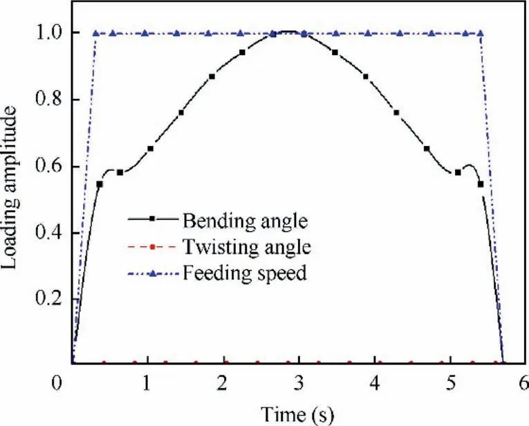
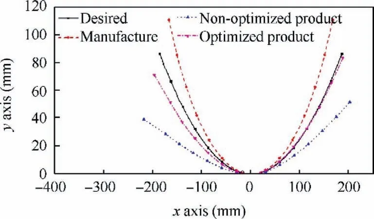
B&T method is implemented (Bending radius ρ and twisting angle φ are considered as compensation magnitudes).Element length is set by 30 mm.So,there exist 13 nodes for the first instance and 11 nodes for the second instance.The loading amplitudes for the first instance are shown in Fig.17.The initial maximum value for the mobile die rotation angle is 0.216 rad (The product of the maximum rotation angle and the amplitude function can be used to represent the Instantaneous rotation angle value in the working process).Without compensation,the springback results are shown in Fig.18(noted as non-optimized product shape).Obviously,the deviation between the desired shape and non-optimized product shape are too big.To reduce the deviation,the bending radii is compensated by increasing the value of maximum rotation angle of mobile die.By using simulation,the maximum rotation angle of mobile die is increased to 0.248 rad.And the simulation results are shown in Fig.18 (noted as optimized product shape).It is found that the shape errors decrease greatly.

Fig.17 Loading amplitudes for 2D tube product.

Fig.18 Shape compensation before and after optimization(2D).
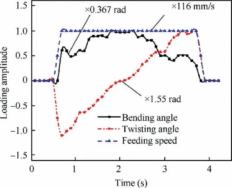
For the second instance,the amplitude used in simulation is shown as Fig.19.The initial maximum value for the mobile die rotation angle is 0.33 rad.The initial maximum value for the clamp rotation angle is 9.5×10⁻³rad/mm.The forming results are shown in Fig.20 (noted by non-optimized product shape).Obviously,springback causes a big deviation between the desired shape and forming product.By compensation,the maximum value for the mobile die rotation angle is increased to 0.367 rad.The maximum value for the clamp rotation angle is increased to 13.3×10⁻³rad/mm.The forming results are noted by optimized product shape in Fig.20.It can be seen that the shape errors also decrease.

Fig.19 Loading amplitudes for 3D tube product.

Fig.20 Shape compensation before and after optimization(3D).
From Figs.19 and 20,it can also be seen that the forming shapes are asymmetrical even though the symmetrical amplitudes are adopted in simulation.This phenomenon can partially be explained as follows:the process parameters are asynchronized with the tube deformation in flexible push bending.The asynchronization will also increase the difficulty of parameters compensation.So,in the following section,only half of the specimens are used for measuring the shape errors.The measuring regions and results are shown in Table 2.Shape errors of the right part of 2D bending product is measured.It can be seen that the comprehensive shape errors reduce from 18.67 mm to 1.516 mm.At the same time,the maximum shape errors reduce from 38.42 mm to 3.60 mm.Shape errors of the left part of 3D bending product is measured.It can also be seen that the comprehensive shape errors reduce from 6.949 mm to 1.959 mm,and the maximum shape errors reduce from 14.311 mm to 2.754 mm.Thus,the B&T method can be considered to partially effective.
The simulation results also show that the deviation caused by several over-bent elements can be counteracted by the deficient-bent elements,just as the phenomenon shown in Fig.6 and Table 1.This principle is helpful to reduce the difficulty of parameter determination in future.

Table 2 Shape errors before and after optimization.
4.2.Manufacture and measurement
According to the principle of bending and twisting machine in Fig.11,a computer controlled tube bender is designed as shown in Fig.21.The aim of experiment is to validate the practicability of the B&T method and demonstrate that the shapes acquired by using the compensated forming parameters are better than those acquired by using the non-compensated forming parameters.

Fig.21 Equipment for spatial tube manufacture.
Forming parameters are extracted from the manufacture shape according the strategies.31All the manipulation modules are controlled by the programs on computer.Feeding speed is controlled stably.Bending speed and twisting speed are set according to the loading amplitudes in Figs.17 and 18.Products are shown in Fig.22.The product shapes using the optimized forming parameters are in better agreement with the designed shape.

Fig.22 Tube products manufactured by equipment above.
5.Discussions and conclusions
(1) The manufacture of 2D/3D spline bent tubes in flexible bending process in previous literatures is usually considered as incremental forming.Quality inspection is usu-ally focused on single part of the tube product,which may cause an accumulation of shape errors and lead to low precision of the product shape.
(2) In this paper,a new comprehensive strategy for springback control of 3D tubes is proposed.In the new strategy,the manufacture shape is defined as an interim geometry.Springback control is conducted by optimizing the manufacture shape,of which the procedure is similar to the DA method in previous literatures.However,considering that the DA method can also cause other problems such as the uncertainty of compensation directions and compensation magnitudes,a new compensating method (B&T method) is established.Compared with DA method,the B&T method is more convenient for implementing (In B&T method,there is no need to care the compensation directions,and all the attentions are focused on the modification of compensation magnitudes).Since the forming parameters on manufacture shape change continuously from one tube element to the adjacent element,the new strategy presented in this paper can solve the problems introduced in Section 2.
(3) Typical 2D/3D tube products are chosen for springback compensation to validate the effectiveness of the new strategy in this paper.Results are shown in Figs.18,20 and Table 2.For the 2D bending product,the comprehensive shape errors of right part reduce from 18.67 mm to 1.516 mm.At the same time,the maximum shape errors reduce from 38.42 mm to 3.60 mm.For the 3D bent tube product,the comprehensive shape errors of left part reduce from 6.949 mm to 1.959 mm,and the maximum shape errors reduce from 14.311 mm to 2.754 mm.Such tendencies mean that the strategy presented in this paper has a positive effect on the designing of forming parameters.
(4) When using B&T method to compensate the springback in flexible push bending.The process parameters are asynchronized with the tube deformation.Even though the symmetrical amplitudes are adopted in simulation,the forming shapes are still asymmetrical.The asynchronization increases the difficulty of parameters compensation greatly.In future,the research emphasis should be placed on the analysis and optimization of compensation magnitudes.
(5) The B&T strategy can also be applied to die bending industry.In the die bending process,the manufacture shape is actually the compensated die surface.Such strategies can help to optimize the manufacture parameters and improve the forming quality of 3D tube products.In future applications,it has potential to achieve better effects than DA method.
Acknowledgement
This work was supported by Key Research and Development Program of Shaanxi of China (No.2020ZDLGY01-05).
 CHINESE JOURNAL OF AERONAUTICS2021年11期
- CHINESE JOURNAL OF AERONAUTICS的其它文章
- Parameter effects on high-speed UAV ground directional stability using bifurcation analysis
- Supersonic flutter control and optimization of metamaterial plate
- Review of in-space assembly technologies
- Utilisation of turboelectric distribution propulsion in commercial aviation:A review on NASA’s TeDP concept
- The influence of inlet swirl intensity and hot-streak on aerodynamics and thermal characteristics of a high pressure turbine vane
- Full blended blade and endwall design of a compressor cascade
