Utilisation of turboelectric distribution propulsion in commercial aviation:A review on NASA’s TeDP concept
Mosab ALRASHED,Theoklis NIKOLAIDIS,Pericles PILIDIS,Soheil JAFARI
Turboelectric Engineering Group,Cranfield Campus,Cranfield University,Bedfordshire MK43 0AL,UK
KEYWORDS Futuristic propulsion systems;Hybrid aircraft engines;Numerical modelling and simulation;Turboelectric distributed propulsion;Turboelectric power
Abstract Emissions produced by the aviation industry are currently a severe environmental threat;therefore,aviation agencies and governments have set emission targets and formulated plans to restrict emissions within the next decade.Hybrid aircraft technology is being considered to meet these targets.The importance of these technologies lies in their advancements in terms of aircraft life cycles and environmental benignity.Owing to these advancements,hybrid electric systems with more than one power source have become promising for the aviation industry,considering that the growth of air traffic is projected to double in the next decade.Hybrid technologies have given future hybrid fans and motor-fan engines potential as alternative power generators.Herein,Turboelectric Distributed Propulsion (TeDP)is discussed in terms of power distribution and power sources.The fundamentals of turbofan and turboshaft engines are presented along with their electricitygeneration mechanism.TeDP is discussed from a design viewpoint,with a detailed discussion of different types of hybrid electric and turboelectric systems.Examples of proposed TeDP aircraft models and numerical modelling tools used to simulate the performance of TeDP models are reviewed.Finally,innovative turboelectric systems in which electric power savers and mechanical gear changers have been discarded for weight optimisation are presented along with other prospective models,engines,approaches,and architectures.The findings of this review indicate the knowledge gaps in the field of numerical modelling for NASA’s TeDP and its capability to increase the efficiency by up to 24% with a 50% reduction in emissions relative to those of conventional gas turbines.
1.Introduction
Since the advent of aviation,significant advances have been made in aircraft technology.One primary example of such an advancement occurred during the Second World War,where tubes and wings were developed for the aviation industry.Over the past decade,the need for more efficient,economical,and environmentally friendly aircraft has led to a series of studies on improving aircraft technology.These studies proposed several power sources and technologies to harvest higher power density.From the introduction of 12-hp (1 hp=745.7 W) engines,technology has advanced to such a degree that the National Aeronautics and Space Administration (NASA) intends to achieve 54400 hp in their N3-X aircraft in the near future1,2.Turboelectricity is the key to generating this massive amount of power,and it has been demonstrated that electric power significantly improves aircraft efficiency.
From a historical perspective,the introduction of electric power systems in aircraft has faced significant challenges despite the advantages of these systems.Beginning from their use in the 1940s and 1950s,electric power systems,such as twin 28-V Direct Current(DC)power generator systems,have been shown to boost aircraft power.These systems were fitted with batteries and inverters to power Alternating Current(AC)aircraft instruments up to 115 V.Valinat introduced electric landing gear in the 1950 s,which required four 115-V AC generators in parallel to provide more control and protection3.Increasing the use of electric power systems in aircraft has been shown to be favourable,delivering AC values higher than 230 V for the recent passenger aircraft,A350 XWB4.
Alternative power generators in aircraft engines support the integration of gas turbines and electric power.This alternative integration of mechanical and electric power is considered an intelligent propulsion source of power.Furthermore,it would replace legacy gas turbine propulsion systems.The requirement of optimum power efficiency makes such a source necessary.Moreover,the full electric distribution of power has significant drawbacks such limitations in power conservation technologies,large space required to carry electrical feeds,and long charging time.Just-in-time implementation of electric power systems,which provide the power density needed for the journey,is essential in aircraft.Power can be generated when required,or it can be supplied from a power storage unit.Both these methods have their advantages and drawbacks in terms of weight,emissions,costs,and power efficiency.
Several review articles have been published regarding Turboelectric Distributed Propulsion (TeDP).The first article introducing turboelectric power was published by Lichtenberg5in 1971,who published a comparative study on the thermal efficiency of diesel and turboelectricity for use in railways.In 1983,Keszei et al.6presented measurement techniques using electronic instruments and discussed the advantages of the proposed technique.In 2012,Armstrong et al.7studied the configuration of and improvements in the N3-X aircraft developed by NASA.Nalianda and Singh8provided a general overview of the opportunities,benefits,and challenges of TeDP.Finally,Brelje and Martins9discussed the electrical fundamentals and concepts of electric fixed-wing aircraft models.
Currently,there is little information available on the status of turboelectric power in aircraft,and hence,it is necessary to review the fundamentals of TeDP technology and its possible future applications;this is especially necessary to educate novices with no background in aviation and thermal power.The focus of this review is to discuss the proposed TeDP models and concepts for future advancements.This review also covers aero-engines,numerical simulations,and existing TeDP technologies.As our focus is on the science of TeDP implemented in the category of More Electric Aircraft (MEAs)and not on the individual types of aircraft or proposed projects,we provide a broad,novel overview.This work will serve as the basis for research on TeDP in the fields of electrical and mechanical expansions.
In the second section of this review,the types of engines that can be used in distributed propulsion systems and the differences between two legacy power engines,Turbofan and Turboshaft,are discussed.Then,some proposed engines that are still in the research and development stage are discussed.These two types of engines were used because of their ability to generate electric power while achieving the highest efficiency in gas fuelling.Furthermore,these types are the most reliable and commonly used in commercial aviation.
2.Fundamentals of turbofan power and propulsion engines
The power generated in the wings and tail of an aircraft is distributed by a number of turbofan engines located in the wings(one or two engines on both sides) based on aircraft design.There are several types of turbofan engines,depending on the number of shafts in the engine (one,two,or three shafts).These engines are designed to merge the thrust from two sources,starting with the inlet and ending with the nozzle10,11.Thrust is generated in the turbofan engine according to the following principle12:
(1) Air enters the engine from the inlet to the fan.
(2) A portion of the flowing air mass is compressed in the compressor,and another portion is compressed in the fan nozzle.
(3) High-pressure compressed air enters the combustion chamber,which increases air temperature by fuel combustion.
(4) The generated high-temperature and high-pressure air enters the turbine and then the propelling nozzle to generate thrust required to propel the aircraft.
Fig.112shows a schematic of the stages involved in thrust generation in the CFM56 engine,which is a typical turbofan engine.This engine is characterised by a forward-facing fan that makes air move by entering the core engine or passing through the bypass duct,from which the bypass ratio can be determined.The bypass offers the following advantages:(A)a low engine noise and(B)a high thrust at low aircraft speeds.Table 113compares the technical specifications of the conventional CFM56 turbofan engine and the proposed concept of advanced turbofan engines.Thrust and specific fuel consumption results in the table were calculated using an in-house tool developed by Cranfield University (TurboMatch).
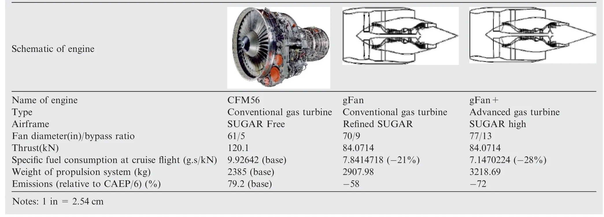
Table 1 Comparison of technical specifications of conventional and proposed advanced turbofan engines.13
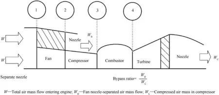
Fig.1 Schematic of stages involved in thrust generation in CFM56 turbofan engine with bypass.12
Flexibility,efficiency,and performance are the three factors that determine the number of shafts or spools in gas-turbine engines.A spool is a rod that delivers power (speed) to all the attached components.If there are multiple spools,power is divided into multiple rods,which implies more control is required for different components of the engine rather than one power or speed for all the components.The multiplespool design makes the gearbox unnecessary and increases the number of stages in gas-turbine engines.For example,in a two-spool engine,the compressor section consists of two stages:a Low-Pressure Compressor (LPC) and a High-Pressure Compressor (HPC);they are arranged in sequence and connected to different spools9–11.The same concept is used for the turbine section,which consists of a High-Pressure Turbine (HPT) and a Low-Pressure Turbine (LPT)arranged in sequence.In a three-spool engine,there are three stages in the turbine section,viz.(A) HPT,(B) Intermediate-Pressure Turbine (IPT),and (C) LPT.However,the compressor still consists of only two stages (Intermediate-Pressure Compressor (IPC) and HPC),where the fan shares the same LPT work instead of the LPC.A comparison between multiple spools is presented in Table 2.Fig.214shows an example of a two-spool turbofan engine.
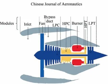
Fig.2 Schematic of a two-spool turbofan engine(the first spool is highlighted in yellow,and the second spool is highlighted in dark blue).14
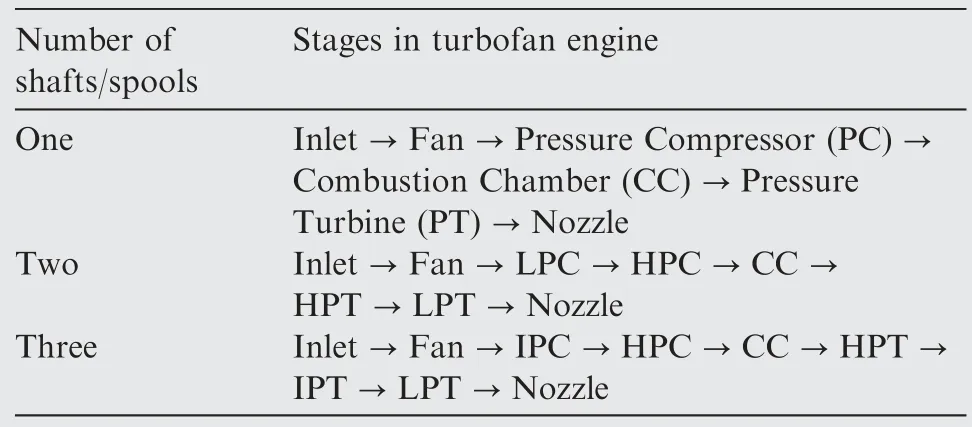
Table 2 Comparison between one-spool,two-spool,and three-spool turbofan engines.
The concept of turbofan engines is crucial not only for current baseline aircraft but also for future aircraft.Future aircraft with increased electric power will use turbofan engines to generate thrust,electricity,or both.Most TeDP models suggest using turbofan engines owing to their efficiency and flexibility.
3.Foundation of power from turboshaft engines
Removing the bypass duct from a turbofan engine reduces thrust,but it increases engine power while reducing engineweight.Moreover,from a technical standpoint,the fan stage does not appear as a station point when estimating the performance of the turboshaft engine.Similarly,using multiple shafts will increase the power of turboshaft engines.
In Fig.3,which illustrates the air-mass flow in a turboshaft engine,it can be seen that air flows through the inlet and then into a compressor.This highly compressed air then enters the combustion chamber,where it is burned along with fuel.The power generated is transferred to the power shaft,which drives the turbine.
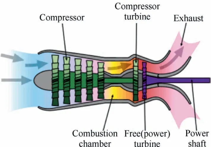
Fig.3 Schematic of air-mass flow in a turboshaft engine.
4.Future engine designs for increased electric power supply
Several aircraft engines with high electric power have been proposed for use in the next decade such as NASA’s N3-X(introduced in 200815),Boeing SUGAR (built-in 201416),and ESAero ECO-150 (developed in 201517).The two main objectives of such aircraft are to include a power generator as a hybrid engine or rotating motors as motor-fan engines.The relationship between propulsion and power sources should accomplish one or both of the following goals:convert mechanical power into electric power (for power generators)or convert electric power to mechanical power.In addition,power storage should also be included (where necessary),depending on the proposed design for TeDP.This section is focused on several reliable engines,which are expected to be the next-generation engines in the aviation market.Futuristic engines are being mainly designed and developed by the cooperation of four organisations,namely NASA,General Electric,CFM International,and Georgia Institute of Technology2,18–20.The realistic engine designs developed at these institutions are expected to shift the usage from baseline engines to hybrid power source engines by 2020.There are two main types of engine models currently undergoing research and development:the generator hybrid fan and motor fan engines.
4.1.Generator hybrid fan engines
The state-of-the-art hybrid engines are geared towards MEAs.As the name implies,hybrid engines consist of baseline engines and conventional gas turbine engines with an electric generator.This concept was introduced in several types of designs.Based on the relationship between power and weight,reducing the weight of materials needed for the carriage will save more power and thus improve fuel efficiency.However,it is challenging to source suitable materials to manufacture lightweight,yet efficient components.As a result of these futuristic technologies,weight was not included in the research calculations since the significant advances are being made in the field of composite materials to reduce the weight as much as possible.The weight would only be considered to determine projected power targets.To overcome this limitation,the justin-time power generator was introduced for TeDP without any power storage,resulting in a flexible and controllable power source.
(1) One of the factors that make just-in-time power generators promising is that they integrate the design of several existing engines21,22.Table 321provides details of a hybrid fan engine proposed by NASA and named gen-Fan as the amalgamation of generators and fans.
(2) Fuel-cell hybrid engines can be used to increase engine efficiency;these engines work on the principle of a Proton Exchange Membrane (PEM)-based fuel-cell stack22.The‘fFan’is a fuel cell gas turbine hybrid device with a single-spool gas generator.The power generated can be delivered to the attached motor fan,batteries,or other electric propulsion units.This type of engine was developed by Boeing;see Table 419for more details.
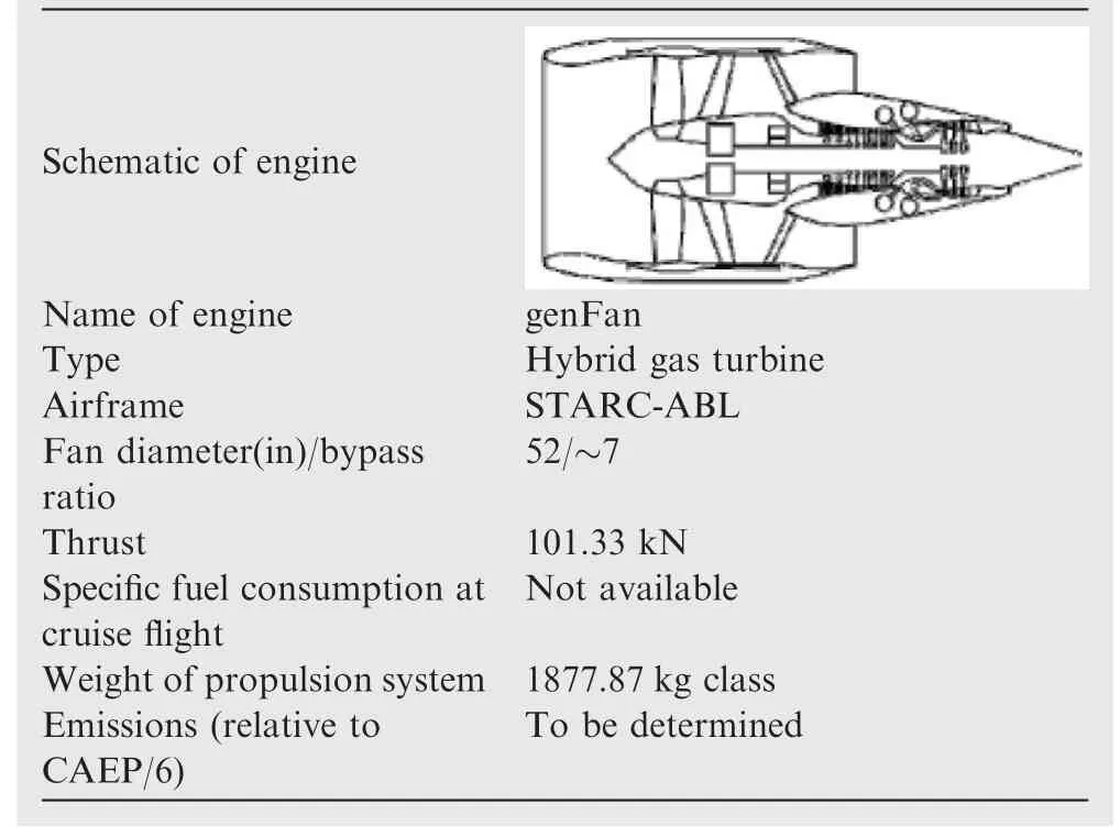
Table 3 Concept hybrid genFan engine.21
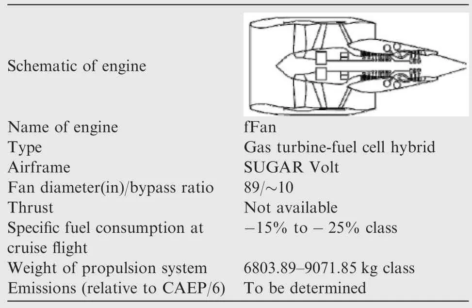
Table 4 Concept hybrid fFan engine.19
4.2.Motor-fan engines
(1) The ‘eFan’ is an all-electric motor propulsion engine consisting of an electric motor;depending on the aircraft model,it can be attached to a high bypass fan,which can be connected to a gearbox19.The engine runs using an external electric power source,which can be batteries or other alternative electric units,to generate the power required for the mission.Table 519shows the specifications of the all-electric motor propulsion engine,‘eFan.’
(2) The ‘hFan’ hybrid fan engine is an advanced version of the conventional CFM56 gas turbine engine,which has a larger fan diameter (by 28 in) and a higher take-off thrust (by 2600 lb,1 lb=0.454 kg) compared to the hFan engine.The lower thrust of the hFan engine can be attributed to a higher percentage of power-sharing between the generator and the turbine.Table 619presents the integration of a Boeing hFan engine in a SUGAR Volt airframe.The ‘hFan’ is a gas turbineelectric hybrid engine that can work in three different modes,as shown in Fig.4.

Fig.4 Thrust modes of hFan engine.
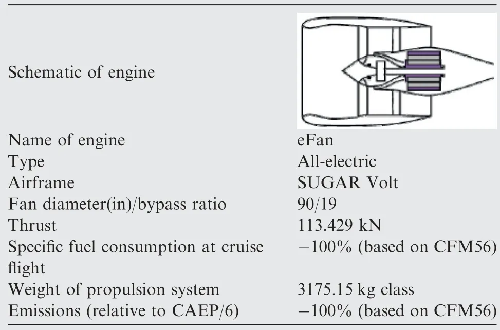
Table 5 Concept of an all-electric motor-fan engine.19
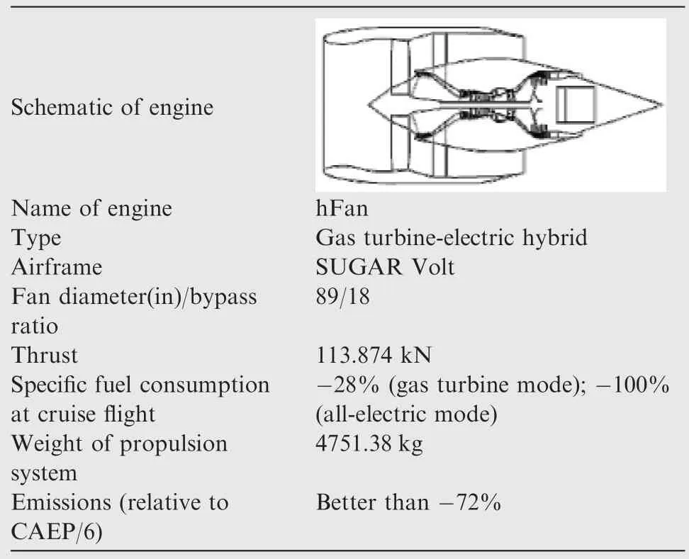
Table 6 Concept hybrid motor-fan engine.19.
These modes can be described briefly as follows:
(1) Mode 1 (complete gas turbine mode):In this mode,the output power is produced in a manner similar to that followed in a baseline turbofan engine.This means that thrust generated for the aircraft is derived solely from fuel combustion.
(2) Mode 2 (hybrid mode):In this mode,both Mode 1 and Mode 2 work together and thus,both fuel and electricity are used as power sources.
(3) Mode 3 (all-electric mode):In this mode,the engine works as a motor-fan engine and external electric power is required to drive the motor.
5.Comparison criteria for distributed electric propulsion
Different MEA networks provide new concepts and basis for modelling distributed propulsion.These networks primarily consist of four significant parts that differ in their propulsion methodology.The major components used in different propulsion systems are shown in Fig.5.23

Fig.5 Components of distributed electric propulsion23.
These components are used for all-electric,more electric,and hybrid distributed propulsion systems.Propulsion systems differ in the following aspects:(A)the amount of carbon dioxide (CO2) and nitrogen oxide (NOx) emissions,(B) output power generation (which is dependent on mission requirements),and (C) class of the aircraft (which can be megawatts or kilowatts).
5.1.All-electric distributed propulsion
All-electric distributed propulsion can be regarded as a green propulsion system because it results in zero CO2and NOxemissions.
Fig.6 shows a schematic of the all-electric distributed propulsion system.The power source (such as the battery in the figure) is connected to the motor to rotate the engine fan.The source should be recharged on the ground prior to each mission,and the number of motors is generally dependent on the type of aircraft.Therefore,the relationship between the number of motors and power sources is a many-to-many relationship24,which means that many motors can be attached to many power sources.
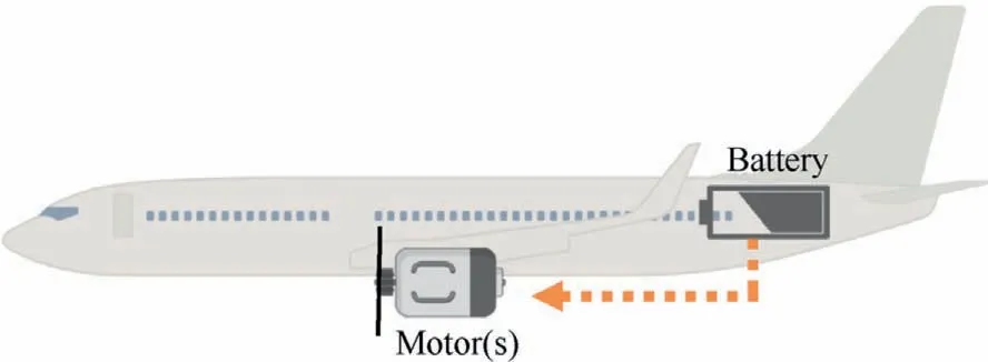
Fig.6 All-electric distributed propulsion.
5.2.More electric/hybrid electric distributed propulsion
In the current field of energy research,the term‘hybrid’implies that there is more than one type of power source.As the name implies,the term‘more electric’provides baseline aircraft with more electrical energy to increase thrust.There are two types of hybrid systems:full and partial hybrid systems.In full hybrid systems,thrust is generated by one or more engines or a combination of engines.Partial hybrid systems have multiple engines or a combination of engines to generate thrust.Each type of hybrid system(full or partial)can be further classified as parallel and series hybrid systems,which will be described in the following subsections.
5.2.1.Parallel hybrid distributed propulsion
In parallel hybrid distributed propulsion (Fig.7),the power source(such as the battery in Fig.6)is connected to the electric motor to rotate the engine fan.However,the electric motor works in parallel with the turbofan as the second source of thrust.Thus,the motor and turbofan serve as a booster for the baseline engine24.Moreover,the cardinality of the relationship between the batteries and motors can be extended to a many-to-many relationship,depending on the turbofan engine of the aircraft.The types of relationships,which illustrate exchange between model elements,are presented in Table 723,considering the number of important concepts that can be implemented23.XandYin this table represent element components,while the description denotes the number of elements used relative to the other element.
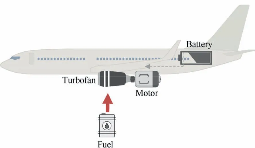
Fig.7 Parallel hybrid distributed propulsion.

Table 7 Analysis of relationships between two elements.23
5.2.2.Series hybrid distributed propulsion
Apart from providing hybrid distributed propulsion,the series hybrid system divides the propulsion thrust into a series relationship between the motors and the turboshaft engine.Motors in a series hybrid distributed propulsion system work as a separate aircraft engine.In addition,there is an electric generator that acts as an electric power source to run the motor or charge the battery in the series connection.Consequently,when electric power is needed,a part of the work generated in the turbofan will be consumed.A full hybrid engine uses a turboshaft,and most of the power generated is consumed in the motors24.Fig.8 shows the concept of series hybrid distributed propulsion and power generation from motor engines.
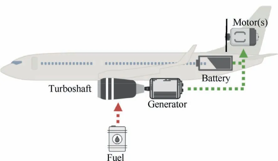
Fig.8 Series hybrid distributed propulsion.
5.2.3.Series/parallel partial hybrid distributed propulsion
As described previously,multiple engines are used to generate thrust in partial hybrid distributed propulsion,and these engines work simultaneously in parallel.Other series-connected sources may also be used to generate thrust.Fig.9 shows the concept of series/parallel hybrid distributed propulsion.The decision to use parallel or series hybrid distributed propulsion(indicated by the blue circle in Fig.9)depends on whether the battery supplies power to the motors and generator simultaneously or separately16,23,24.However,if the battery is not used as the power source,it is used to charge the generator,which then supplies power to motors.Even though the number of motors,generators,and batteries is generally dependent on aircraft design and model,the concept of partial hybrid distributed propulsion (series or parallel) is similar.
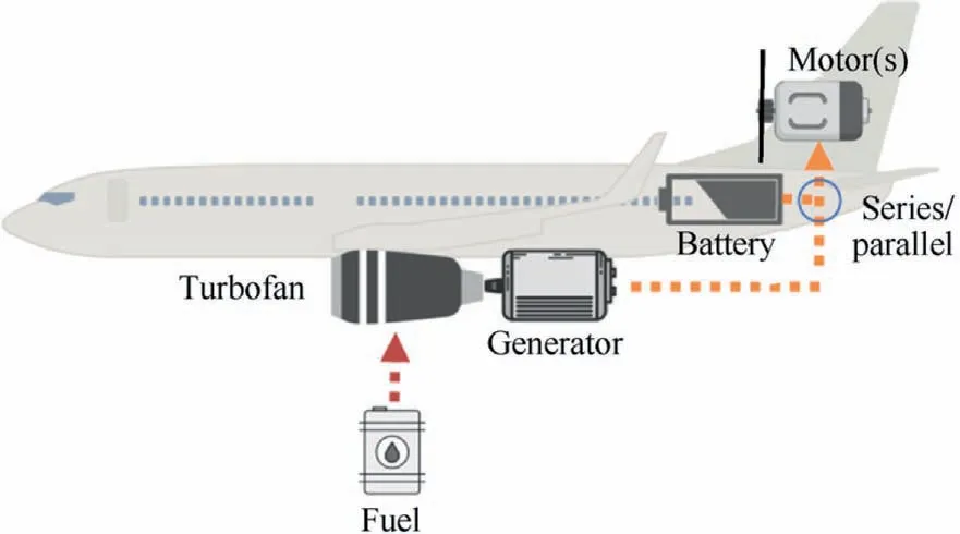
Fig.9 Series/parallel partial hybrid distributed propulsion (‘‘s”means more than one motor).
5.3.Quantitative analysis for hybrid distributed propulsion
Based on the previous discussion of futuristic distributed propulsion systems,a quantitative comparison was conducted to examine the advantages and drawbacks of each type.The comparison evaluated three parameters,namely,efficiency,emission,and cost.The propulsion systems were evaluated using the criteria-rated percentage as follows.
(1) Efficiency2,25,26
(A) Analysis method
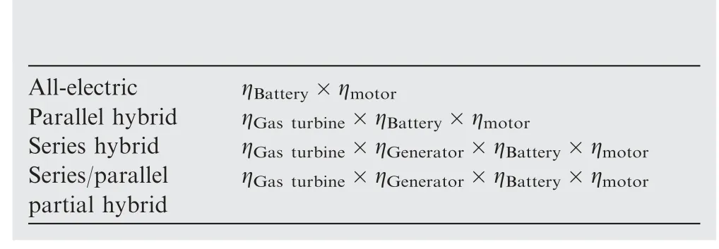
(B) Assumptions

(2) Emission analysis25,26
(A) Analysis method
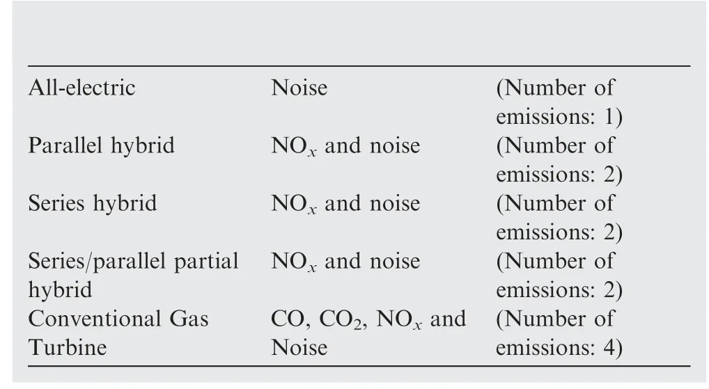
(B) Assumptions

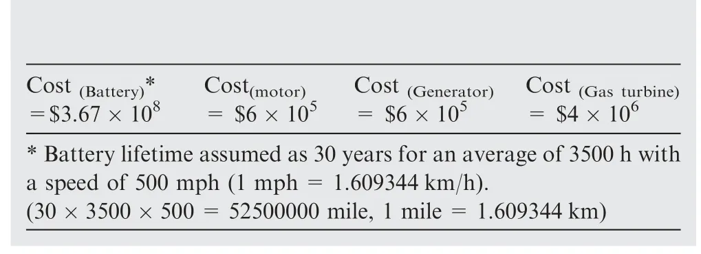
(3) Cost analysis27–35
(A) Analysis method
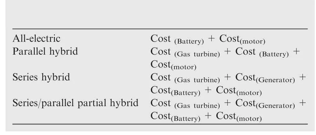
(B) Assumptions
The final analysis results reveal that the series hybrid has the most disadvantages,whereas the all-electric model exhibited the most advantages.The series and parallel hybrids achieve the highest propulsion system power,whereas the all-electric model performs best with respect to aircraft weight and emission productions.However,in terms of technology and cost,the parallel hybrid and all-electric models exhibited almost identical results,which are the lowest among the models.Fig.10 presents these results and the analysis of the different distributed propulsions.From the analysed results,it is evident that the all-electric system achieves the highest efficiency.The emissions levels of this system are 25% of those of conventional gas turbines,and the cost of this system is 91%greater.
Table 8 lists the data used to quantitatively assess the alternative distributed propulsion systems.This table and Fig.10 compare different types of proposed systems with the conventional gas turbine system.For example,the all-electric system is 81%more efficient,with 25%of the conventional emissions,but it costs 91% more than the conventional system,resulting in a total cost of 191%.
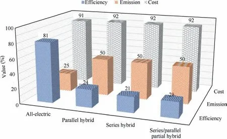
Fig.10 Comparison between alternative distributed propulsion system and conventional system.
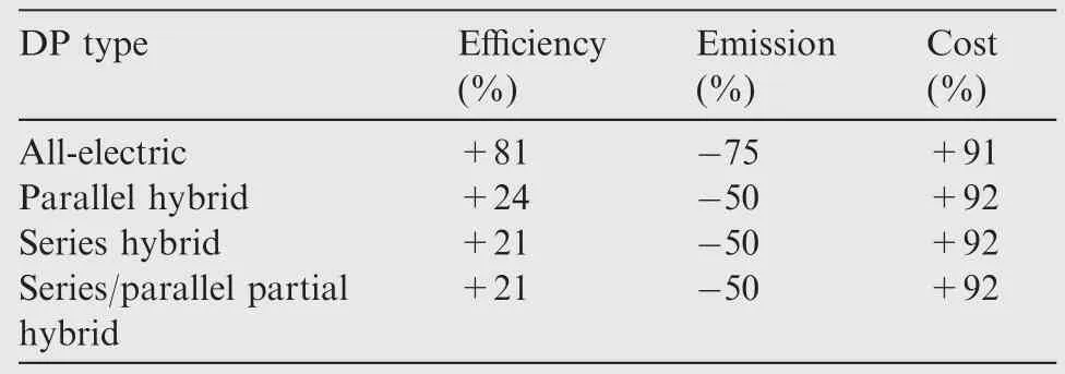
Table 8 Assessment of alternative distributed propulsion methods relative to conventional system.
6.Advances in turboelectric conceptual designs
TeDP design is based on the concept of ‘just-in-time’ energy generation.This design reduces energy wastage and increases aircraft reliability,particularly in the event of single-engine failure.In addition,TeDP reduces battery weight and overcomes technological limitations to save energy16,24,36,37.Currently available TeDP aircraft designs can be used totransport 300 passengers at a maximum speed of 0.78–0.84 Mach38,39.Previous TeDP aircraft designs had a higher bypass ratio (hybrid wing-body designs) compared to baseline tube and wing aircraft.In general,the primary difference between different generations of TeDP aircraft is the aircraft design and number of motors,which depends on fan size rather than the required thrust.Two types of hybrid TeDP,full and partial hybrid TeDP,are discussed in the following sections.
6.1.Full turboelectric distributed propulsion
The TeDP or full TeDP design(Fig.11)includes a turboshaft,and most of the thrust is generated by the motors.In theory,the turboshaft must deliver most of the power to the electric generator,which means that more electric power is distributed to the motors24.The relationship between the turboshaft and generator is a one-to-one relationship,whereas the relationship between the electric generator and motors is a one-to-many relationship.
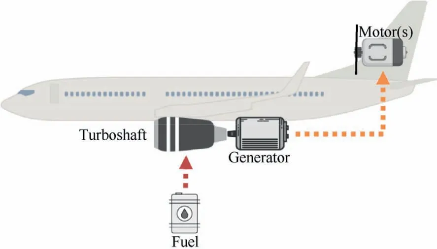
Fig.11 Full turboelectric distributed propulsion.
6.2.Partial turboelectric distributed propulsion
Depending on the baseline engines and thrust,in partial TeDP,more thrust or power is generated using electric engines24.Fig.12 shows the concept of partial TeDP.The analytical relationship between full and partial TeDP components is similar,and this relationship is dependent on the TeDP design proposed for the aircraft.The only difference between full and partial TeDP depends on the gas engine used.If the turbofan is attached to the TeDP system,then part of the thrust will be obtained from the gas turbine engine and the remainder from the motor-fan.
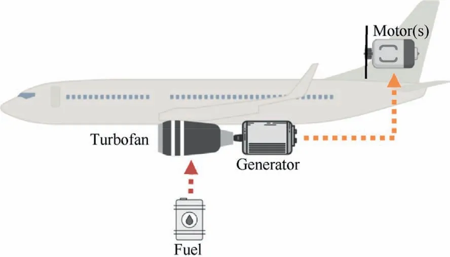
Fig.12 Partial turboelectric distributed propulsion.
6.3.Quantitative analysis for TeDP
Based on the data available for each type of TeDP,a quantitative analysis was performed for three parameters,namely,efficiency,emission,and cost.These results indicate the advantages of each type relative to one another.The evaluation method established weights for the parameters depending on the model,components,and expected performance.The system was evaluated using the criteria-rated percentage as follows.Fig.13 illustrates the results of this analysis.
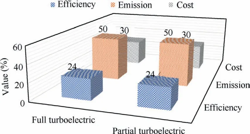
Fig.13 Comparison results between two types of turboelectric full and partial distributed propulsion.
(1) Efficiency2,25,26
(A) Analysis method

(B) Assumptions

(2) Emission analysis25,26
(A) Analysis method

(B) Assumptions
All proposed alternative turboelectric systems are fuelled by hydrogen.
(3) Cost analysis27–35
(A) Analysis method

(B) Assumptions

Table 9 lists the data used to assess the different types of TeDP.The evaluation was performed based on the overall comparison results while accounting for a standard marginof error.The result of this analysis shows that the two types of turboelectric systems are expected to reduce emissions to half of that of conventional gas turbines with a 30% increase in cost.In total,the system will be 24%more efficient but its cost is 130% that of conventional gas turbines.

Table 9 Comparison assessment of alternative turboelectric distributed propulsion methods.
7.Examples of proposed turboelectric distributed propulsion aircraft models
When discussing TeDP designs,it is essential to include proposed aircraft designs with advanced concepts to show how each TeDP component fits in the aircraft to deliver an alternative solution.The TeDP design depends on the class of the aircraft and must produce the necessary kilowatt or megawatt power for the motor fans.
7.1.Single-aisle turboelectric aircraft model
Among the most reliable models,the one that is closest to being ready for commercial use was introduced by NASA and developed by Boeing.The main feature of this model is that the aircraft tube and wing design are retained while some modifications are made to the body;these modifications provide an alternative solution for the motor-fan design.
7.1.1.STARC-ABL
NASA’s Langley Research Centre (LRC) has developed a single-aisle turboelectric aircraft model with aft boundary layer propulsion (STARC-ABL).This aircraft can carry more than 150 passengers for 3500 nautical miles16,21–24,36–40.The aircraft design introduces TeDP with twin underwing turbofans and a rear fuselage boundary layer for electric motor fans.This design is the most suitable for single-aisle class commercial transport.This design aims to reduce fuel consumption and emissions as compared to the current baseline aircraft model.Fig.14 shows the STARC-ABL model and the connection network between TeDP components.
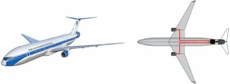
Fig.14 NASA’s STARC-ABL aircraft design (model scale is 1:48).
Electricity is generated by two underwing turbofans.Rotational power from the turbofan shaft rotates the electric generator,which extracts electric current.Fuselage propulsion in the aircraft tail absorbs electric power from the underwing electrical generators and transmits it to the rear electric motor fan.This fan can operate continuously at 3500 hp and a pressure ratio of 1.25.The pressure ratio is calculated by dividing the total pressure in the nozzle section by the total pressure in the inlet fan section41.
7.1.2.E-thrust concept
The concept of e-thrust (illustrated in Fig.1542) is based on distributed electrical aerospace propulsion;it was developed jointly by Airbus Group Innovations,Rolls Royce,and Cranfield University42.This concept is based on a hybrid distributed electric propulsion;it is a 1:6 relationship model,where one power engine runs six smaller motor-fan engines to generate the required thrust.

Fig.15 E-thrust concept42.
7.2.Hybrid wing-body aircraft model with turboelectric distributed propulsion
The Hybrid Wing-Body(HWB)aircraft model is an advanced design,which differs from the tube wing design powered by TeDP.This advanced design enhances the efficiency of propulsion and reduces emissions,especially acoustic emissions owing to a significant drop in the fan pressure ratio.
7.3.N3-X aircraft model with turboelectric distributed propulsion
NASA has adopted TeDP technology to meet its emission targets by 2050 and develop novel solutions to overcome the challenges faced in the development of the N3-X aircraft.The relationship between TeDP components is 2:16,i.e.,two gas turbine engines work to produce electric power for 16 electric motor fans36.Each gas turbine engine has two electric generators,each of which serves four spread motors.In the event of engine failure,all 16 motor fans work together to produce asymmetric thrust using the four allocated motors.Each motor is powered by a different electric generator.Two electric generators located at the sides of the wingtip produce the required power,and thrust is distributed at the middle rear of the bodywing shape.Table 10 summarises the relationship between TeDP components43,and Fig.16 shows the HWB concept of the N3-X aircraft36–44.

Fig.16 N3-X aircraft concept44

Table 10 Relationship between TeDP components of N3-X aircraft43 (M=Motor).
7.4.Cambridge-MIT-Institute SAX-40
This concept aircraft was presented by a collaborative project conducted by Cambridge and MIT;its novelty was the low noise produced.SAX-40 could carry 215 passengers while producing an estimated 63 dBA acoustic noise.The difference between SAX-40 and N3-X with respect to the propulsion is that the gas turbine engine and motor fans reside on the tail of the aircraft.The idea of this concept is to have one gas turbine surrounded by two motor fans inside one collapse intake and nozzle.In total,this concept comprises three gas turbine engines and six motor fans.Fig.1745depicts the aircraft concept.Additionally,Table 11 illustrates the relationship between the propulsion components45–47.

Table 11 Relationship between SAX-40 aircraft propulsion components (M=Motor).

Fig.17 Concept of SAX-40 aircraft45.
8.Numerical modelling of future aircraft performance
Numerical simulations have been conducted on two types of engineering models,viz.physical and mathematical.The physical model presents natural phenomena,while the mathematical model represents the formalism of physical behaviour48.Due to time and cost constraints,numerical modelling tools are required to facilitate the development of future distributed propulsion,overcome technical challenges in aircraft models,and analyse the proposed optimal solutions.For example,numerical modelling was conducted to estimate the force and impulse of Boeing B737-800 aircraft49.Another study provided an open-source numerical modelling tool to estimate aircraft kinematic performance50.Numerical simulations have also been performed to analyse the collision of an aircraft with a large tank51.
There are some challenges in implementing numerical simulations for the proposed models.Future aircraft require the integration of an increasing knowledge base of electrical phenomena with legacy simulations.Electrical parts and networks influence the performance of hybrid aircraft because they play a role in aircraft propulsion.In addition,the size,weight,heat,and resistance of electrical parts affect the overall efficiency to a greater extent when compared to the calculated power.
Numerical methods used to model TeDP and MEA require a stable,robust,and flexible gas turbine engine simulator.A multidisciplinary simulator commonly used to analyse the performance of gas turbine engines is TurboMatch.It was developed in the 1970s at the Cranfield Institute of Technology(which is now known as Cranfield University)to perform thermodynamic simulations of gas turbine engines52.This modelling tool was later updated to simulate the performance of different types of powerful gas turbine engines.TurboMatch was written in Fortran IV to simulate the performance of various engine designs.The results are presented in the form of characteristic maps of gas turbine components,which facilitates engine performance analysis.Evaluating the methods used to numerically model future aircraft reveals the limitations of an integrated developing environment for assisting tools.
9.Existing studies on TeDP modelling
The number of published studies on TeDP numerical modelling is lower than the number of reports on aircraft design and physical experimentation.In general,studies on TeDP numerical modelling can be classified as follows:
9.1.Simulator
Choi et al.from NASA’s Glenn Research Centre (NGRC)introduced a method to simulate TeDP powertrains to determine the relationship between torque and speed curves53.His work includes an experimental study to emulate the power distributed through TeDP.The model(closed-loop electric motor control drive system)was simulated on MATLAB/Simulink to obtain propulsive fan maps.A Propulsion Electric Grid Simulator (PEGS) is an analytical TeDP model that shows the dynamic characteristics required to control the electric motor drive.This model is still under development,and many electrical components need to be added.Moreover,the performance of the TeDP model has not been evaluated,and therefore,validation is needed to determine the reliability of the model.
A novel TeDP model was developed in 2016 at Cranfield University.This model was simulated using an academic tool called the ‘TeDP_SIMULATOR’,which is not a standalone tool.This tool uses an outsourcing tool to simulate turbo generator performance,and another tool was used to simulate the propulsor54.There is no synchronisation between these tools,and hence,the TeDP model could simulate only one type of shaft-drive gas turbine engine.
Yazar developed a design model for TeDP using MATLAB/Simulink to study the integration of the turboshaft in the turboelectric system55.The simulation results were compared with real data to assess the uncertainty in simulation reliability.The author encourages this study to be extended to consider power system design and management.In contrast,an in-house aircraft sizing tool at Georgia Institute of Technology has been used to assess the thermal implementation of TeDP for the megawatt-class aircraft56.This study focused on the design of turboshaft engines and did not enhance the turboelectric performance as one system.
9.2.Electric architecture
The architecture of an electrical network is as important as the thermodynamics of the propulsor components.The electric architecture is related to the overall aircraft efficiency because the electrical model plays a significant role in determining the weight,size,heat distribution,generated power,and performance of the aircraft.The electric architecture describes the power generated in gas turbines and the resulting electric thrust available for aircraft propulsion57–59.Thus far,researchers have mostly focused on the electric architecture of the N3-X aircraft and its model alternatives.The knowledge base developed based on these models illustrates the limitations and challenges of the superconducting concept.
9.3.Failure
Currently,there is limited information available on the failure of TeDP components.The available reports considered the failure of the electric network,superconducting cables,materials,redundancy management,and design methods.For example,Nolan et al.discussed the effects of superconducting cables on TeDP aircraft performance60.Another study investigated the challenges and benefits that turboelectric systems can present for crewless aircraft61.
9.4.Design
9.4.1.Boundary layer ingestion
Several studies investigated Boundary Layer Ingestion (BLI)fordistributed propulsion to improve future aircraft performance62–64.BLI reduces fuel consumption by reducing propulsive power consumption65,66.Fig.18 shows the BLI concept;it produces less wake and jet kinetic energy while maintaining the same net force67.

Fig.18 Boundary layer ingestion concept67.
It is predicted that,in the future,aircraft efficiency will increase with a decrease in fuel consumption.NASA expects to achieve fuel savings of 7%–8% for the N3-X aircraft by implementing the BLI concept,despite the considerable number of electric components.The fundamental principle of BLI is to reduce wasted kinetic energy by splitting thrust between the propulsor units68,69.Research on an algebraic simulation has been conducted to optimise the BLI for turboelectric aircraft based on the sizing and performance70.This paper presented a more detailed analysis of the conventional configuration.A RANS CFD optimisation simulation done using the OpenMDAO framework is shown in Fig.19 for the BLI fan71.This study recommended having a lower Fan Pressure Ratio (FPR) and analysing a full aircraft optimisation on the thermal and aerodynamic side.
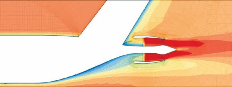
Fig.19 NASA’S STARC BLI RANS CFD71.
Another modelling study aimed to reach 89.95% of the total electric efficiency for a single-aisle TeDP by investigating the development of a power splitter for the fans and simulating turbomachinery degradation72.
9.4.2.Hybrid Wing Body (HWB)
After NASA introduced the TeDP model for the N3-X aircraft,several researchers attempted to study the N3-X model to develop novel solutions73.The challenges in the implementation of this new concept design include finding a way to reshape 300-passenger-class aircraft with more imaginative airframes.Furthermore,the arrangement of numerous motors and generators needs to be distributed within the frame.
9.4.3.Methods
A few methods have been reported to model TeDP;these methods vary in terms of the components included or the outcomes needed from the model.Each researcher has used his/her distinct TeDP modelling method depending on the area of investigation43.For example,Liu et al.54developed a method to calculate the power required for electrical propulsor units.Moreover,another methodology was developed by the same author to reduce fuel consumption and noise emission55.Other published methods for TeDP include a method for speed control that rewarded a 4% reduction in system weight and propellant consumption56and a method for evaluating TeDP architectures61.
10.Promising research areas and future trends
Based on the literature review,TeDP is a promising area of research compared with other alternative futuristic propulsion methods with several research directions.Each part of TeDP could be enhanced,simulated,and optimised in stand-alone research.Moreover,the relationship between two or more components affects the total efficiency.However,achieving a high efficiency of the total system is still being investigated as it is affected by various parameters.The authors identified promising research areas and directions,including future trends categorised as four ‘M’s:modelling,manufacture,mechatronics and merchandise.
10.1.Modelling
This area of research and development aims to overcome the current challenges in aviation with intelligent solutions to surmount technical threats in economic and safety risks.Future trends of scientifically modelling TeDP encompass simulating the architecture of the system.
A few studies have been reported which support this overview.Felder et al.examined the effect of BLI using modelling algorithms and simulation tools published in NASA technical reports.The results of this work indicate that it is desirable to perform design and modelling by integrating electrical and mechanical systems74.Davies et al.studied the fault behaviour of superconductors used in TeDP by employing a modelling and simulation.The results indicate the need to have a wide range of sensitivity studies to cover the fault profile75.
10.1.1.Architecture
The TeDP concept and system implementation has been studied,but the actual design and architecture of each part of the system remains unclear.Detailed research on the structure of hybrid gas turbine engines,electric generators,electric motors,and even the airframe of the aircraft,is required.Future research should consider the impact of fuel requirements on components such as the fuel tank and batteries.
10.1.2.Simulation
Increasing developments in computer software have made it easier to perform complicated simulations.Preliminary studies in this area recommend implementing authentic and professional tools to study TeDP and optimise it.The optimisation techniques include deterministic,stochastic,and artificial intelligence techniques.The thermal reactions between TeDP system elements should also be studied using CFD methods and applications.
10.2.Manufacture
Manufacturing is another promising research area,particularly with the advent of the fourth industrial revolution.Thus far,no TeDP system has been manufactured for commercial use.Only a few emulator prototypes have been applied investigate the performance of TeDP.This is mainly due to the limitations of manufacturing materials and operations.
A collaborative study between NASA,Rolls-Royce,Georgia Institute of Technology,and the University of Strathclyde on TeDP architecture,voltage,and components discussed the importance of manufacturing advancements in aviation research76.
10.2.1.Material
Nanomaterials can be used in TeDP due to their high thermal conductivity.Because of experimental limitations,this research area lacks data that consider improving efficiency.
10.2.2.Operation
Building TeDP systems requires strategic plans and operation management to overcome all manufacturing challenges.Examining the methods that can appropriately manufacture TeDP systems will reduce waste and improve productivity.
10.3.Mechatronics
The integration of mechanical and electrical components in TeDP systems results in the need for mechatronics research.Th research includes the study of computational mechanics,stability,and control77.The authors believe that the primary future directions in TeDP research are control electronics and electromechanics.
10.3.1.Control electronics
The area of control electronics is critical in TeDP as it detects and isolates faults.This consists of current,voltage,and power modes for each component in the grid.Furthermore,it examines the system control strategy for the build-up resistance and inductance to optimise the power efficiency.
10.3.2.Electromechanics
Usage of mechanical power to obtain electricity(generator)or electric power to rotate components using mechanical force(motor)is considered as electromechanics.The research in this area aims to reduce the energy conversion losses as much as possible.Future research on TeDP systems will focus on electromechanical systems that are capable of satisfying the torque and energy requirements in a timely manner.
10.4.Merchandise
Transforming the proposed technology for commercial use needs to be investigated to determine market visibility.Research should analyse the reliability and financial viability of TeDP operation.The research in this area is mainly characterised by two aspects:the industrial sector and the supply chain in the aviation market.
A paper published by Birch at Cambridge University reviewed the market drivers in 2020 for TeDP and their impact on the economy78.This previous publication supports our view by indicating the existing challenges in the aerospace industry are interesting to investigate and require innovative solutions.
10.4.1.Industry
With the growth in the aviation market and improvements in the industrial sector,especially with respect to the evolution of industry 4.0,there is a certain goal that civil aviation must achieve.Shareholders in the industry need to be convinced about the value that TeDP will add to the sector.That is why a major proportion of future research should examine the conversion of legacy industry systems to TeDP.
10.4.2.Supply chain
To ensure adoption of TeDP within the industry,the availability of materials and system parts must be investigated.Moreover,the supply of spare parts and the use of experts to facilitate the new integration can result in effective supply chain management.
11.Analysis of possibilities
This section presents the limitations of TeDP based on data availability.A more in-depth analysis of potential solutions is needed to facilitate future development and identify physical limits.Based on our review,there are several probable avenues to analyse the components in TeDP.These development possibilities are as follows.
11.1.Aircraft airframe
As a novel configuration of airframe is needed based on the concept of turboelectric systems,the distribution of propulsion will be divided between the motor fans and turbofans in one case,or all propulsion will be directed to the motor fans for turboshaft engines.This indicates that the current aircraft structures must be redesigned to integrate motor fans79–81.Moreover,the challenge of utilising gravity balance,space,and weight should be considered in the development80.One of the projected designs used BLI with the risk of one prime mover and noise emission55.However,a practical design has not yet been built or tested for TeDP to the best of the authors’knowledge.Furthermore,researching,designing,investigating,and validating a novel model is expensive.
11.2.Gas turbine engines
The implementation of electric generators inside the gas turbine engine is an interesting research prospect for the thermal performance of both systems.Because of the high level of heat in the turbine,the performance of the electric generator will be negatively affected.High Temperature Superconductivity(HTS) generators also have physical limitations which will reduce the efficiency of the electric power produced36,82.Furthermore,from a modelling and design viewpoint,there are challenges when restructuring the generator to fit the shape of the turbine83.The number of generators to be implement is a development challenge as it may decrease the gas turbine efficiency.
11.3.Electrical motors
There are three main factors that must be considered in the development of electrical motors for the propulsion system:cost,affordability,and technology.For example,the high cost of NASA’s N3-X aircraft stems from the large number of motors used84.The lack of technology development,especially for aircraft motors,results in such high costs.
11.4.Electrical superconductors
This technology is related to the three previously discussed development possibilities to design aircraft embedded with superconducting buses connected to motors and generators36,85.The application of superconducting buses has challenges with regards to their weight,size,design,and manufacturing material86.Some samples of these semiconductors have been developed for research and production purposes,but they are not suitable for aerospace use.
11.5.Numerical modelling
TeDP numerical modelling is critical motivation in accelerating the research in this area.Offering an authentic tool specifically for academic and research purposes to assess TeDP systems will provide insights into these systems and optimise the development of TeDP87,88.
12.Conclusions
The utilisation of electric power in aircraft is revolutionising the aerospace industry.However,the increasing use of electric systems presents significant challenges in the development of aircraft models as well as in the studies conducted to achieve the desired outcomes.Research is being undertaken to address this issue,and several alternative power sources have been proposed to solve future aviation problems,as shown in Table 12.89–99

Table 12 Proposed alternative power sources for future aviation problems.89–99
This review considered various solutions,concepts,and proposed technologies,throughout the history of electric aviation,with the aim of collating knowledge of different electric aviation approaches to facilitate the development of advanced TeDP architecture.Fig.2023,100presents a summary of this review;it describes the different aero propulsion power sources considered and their distribution,including the differences between models related to TeDP.
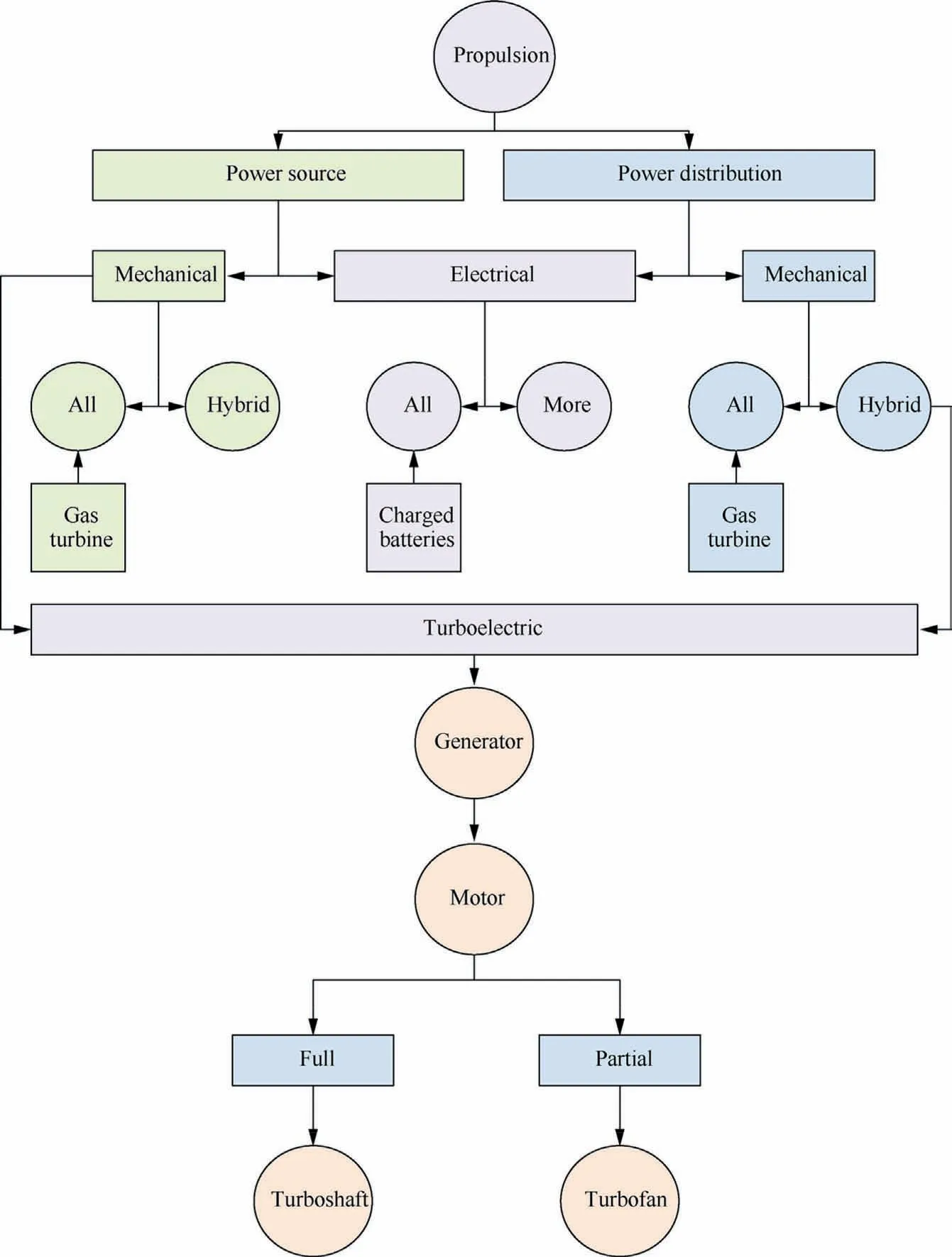
Fig.20 Summary of turboelectric aero propulsion systems23,100.
Most of the studies in this area have focused on increasing the efficiency of current aircraft configurations.These studies have yielded a number of methods to integrate hybrid electricsystems with more the one power source into distributed propulsion on a small scale with limited enhancements.Another apparent research trend is the focus on opportunities and challenges associated with all-electric motors for future implementation in the aviation sector while considering technological limitations.
Future trends in the civilian aircraft sector will be dominated by all-electric and turboelectric motors4,8,35,101,102.Validation studies have been conducted recently to compare the three types of future alternative methods for aircraft propulsion,namely hybrid,electric,and turbo-electric,that affect the TeDP system used101,103.Opinions on the probable future of turboelectric power in civilian aircraft lean towards the use of TeDP for megawatt-class aircraft with 300 or more passengers.TeDP could also be utilised in smaller aircraft if more research is conducted to overcome challenges with respect to design,weight,and material.The critical element affecting the integration of TeDP into the aviation sector is the fuel required to generate power.For example,if hydrogen is used as fuel for TeDP,power can be generated with almost zero emissions using a battery-less system (which results in lower weight) and just-in-time power generation.
To integrate TeDP into this sector,numerical modelling tools must be developed to analyse aircraft performance and optimise the proposed distributed propulsion models.These tools should be geared towards users working in research and development and should incorporate implementation methods to optimise the configuration of future aircraft.
As part of future work,the authors of this review intend to propose a novel method that provides an integration framework environment as a TurboMatch extension to facilitate the analysis of different TeDP systems.
Declaration of Competing Interest
The authors declare that they have no known competing financial interests or personal relationships that could have appeared to influence the work reported in this paper.
Acknowledgements
The authors wish to thank Professor Wael Alrashed of Kuwait University for funding and supporting this project.
Declaration of Competing Interest
The authors declare that there is no conflict of interest.
 CHINESE JOURNAL OF AERONAUTICS2021年11期
- CHINESE JOURNAL OF AERONAUTICS的其它文章
- Parameter effects on high-speed UAV ground directional stability using bifurcation analysis
- Supersonic flutter control and optimization of metamaterial plate
- Review of in-space assembly technologies
- The influence of inlet swirl intensity and hot-streak on aerodynamics and thermal characteristics of a high pressure turbine vane
- Full blended blade and endwall design of a compressor cascade
- Evolution of wall flow structure and measurement of shear stress issuing from supersonic jet with extended shelf
